
Related Manuals for Pfeiffer Vacuum MVP 035-2


Summary of Contents for Pfeiffer Vacuum MVP 035-2
- Page 1 Betriebsanleitung • Operating Instructions Diaphragm Pumps MVP 035-2 MVP 055-3 MVP 055-3C...
-
Page 2: Table Of Contents
Precautions ......... . 17 Cleaning and replacing diaphragm and valves at MVP 035-2 ..18 Cleaning and replacing diaphragm and valves at MVP 055-3 . -
Page 3: About This Manual
1 About this manual 1.1 Validity This operating manual is for customers of Pfeiffer Vacuum. It describes the func- tioning of the designated product and provides the most important information for safe use of the unit. The description follows applicable EU guidelines. All informa- tion provided in this operating manual refer to the current state of the product's de- velopment. -
Page 4: Safety
Safety Command to perform an action or task associated with a source of danger, the disregarding of which may result in serious accidents. Important information about a product, handling or applicable part of the documentation to which special attention should be paid. Instructions in the Work instruction: here you have to do something. -
Page 5: Proper Use
• Installation, operating and maintenance regulations must be complied with. • Using accessories not mentioned in this manual is not permitted without autho- risation from Pfeiffer Vacuum. • When pumping gases which could form explosive or ignitable mixtures, take suitable precautions: –... -
Page 6: Transport And Storage
Transport and storage 3 Transport and storage 3.1 Transport Transport instructions Remove the locking cap from the vacuum flange immediately before connec- ting! Use only the handles provided for that purpose to lift the pump. – Do not use the interhead connections on the top side of the pump to carry the pump. -
Page 7: Product Description
Product description 4 Product description 4.1 Product identification To correctly identify the product when communicating with Pfeiffer Vacuum, al- ways have the information from the rating plate available and use it: • Pump model and model number • Serial number •... -
Page 8: Design And Function
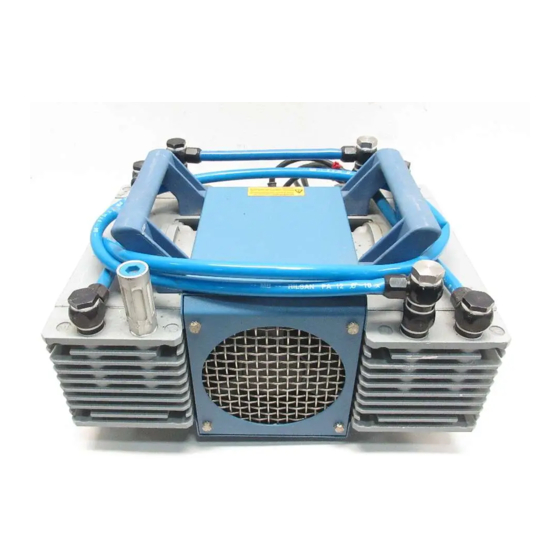
The diaphragm vacuum pumps of the series MVP 055-3/3C are three stage and those of the MVP 035-2 series are two stage, dry compressor vacuum pumps. That means that the supplied medium is not brought into contact with lubrication. The pumps are positive displacement pumps with a periodic change of size of the suc- tion chamber produced by the movement of the diaphragm. - Page 9 Product description A1 Vacuum connection 2.1 Exhaust Diaphragm head 1 Diaphragm head 2 Diaphragm head 3 Diaphragm head 4 Mains power supply Power switch Voltage selector switch 28 Hose connection 40 Gas ballast valve Fig. 4: MVP 055-3C...
-
Page 10: Installation
Installation 5 Installation 5.1 Setting up the pump Installation location Observe the following requirements when setting up the pump: • Note the load-bearing capacity of the mounting surface. • Maximum installation altitude 2000 m (above mean sea level) • Permissible ambient temperature: +12 ... +40°C •... -
Page 11: Connecting To The Mains Power Supply
Installation WARNING Emission of toxic substances from the exhaust! Danger of poisoning from emitted gases or vapours, which can be detrimental to health and/or can pollute the environment, depending on the particular application. Comply with the applicable regulations when working with toxic substances. Only officially approved filter systems may be used to separate out these substances. - Page 12 Installation Switch position: "115" "230" Voltage ranges: 100 ... 120 V, 50/60 Hz 200 ... 240 V, 50/60 Hz Motor protection A self-locking thermal winding protector switches off the pump motor in the event of overheating. Allow the pump to cool off several minutes and do not switch it back on until it has cooled off.
-
Page 13: Retrofitting The Gas Ballast Valve
Installation 5.5 Retrofitting the gas ballast valve As an option, the MVP 055-3 can be retrofitted with a gas ballast valve. Installation The gas ballast valve may only be installed on membrane head 3. Hollow screw 15 at the outlet (Ex) to membrane head 3 using a SW 17 open-end wrench. -
Page 14: Operation
Operation 6 Operation 6.1 Before switching on the pump Compare the voltage information on the rating plate with the mains voltage. Check that the exhaust connection allows free flow (max. permissible pressure 1.1 bar absolute). – Activate the shut-off valves in such a way that they open before or at the same time as the pump is started. - Page 15 Operation WARNING Reactive, explosive or otherwise dangerous mixtures! Uncontrolled gas inlet at the gas ballast valve can result in dangerous mixtures. By implementing the required safety measures, the user must prevent potentially ex- plosive mixtures from occurring in the inside of the pump and from being ignited in the event of a diaphragm crack by mechanically produced sparks, hot surfaces or static electricity.
-
Page 16: Switching Off The Pump
Operation Installing the flushing The MVP 055-3C can be equipped with a flushing gas connection as an option. gas connection Assembly Disconnect connection line from gas ballast valve. Dismantle gas ballast valve and replace with flushing gas connection piece. Restore connection line and connect inert gas line. –... -
Page 17: Maintenance
NOTE Service work should only be carried out by qualified personal! Pfeiffer Vacuum is not liable for any damage to the pump resulting from work carried out improperly. Take advantage of our service training programs from technical training; additional information at www.pfeiffer-vacuum.net. -
Page 18: Cleaning And Replacing Diaphragm And Valves At Mvp 035-2
Check list for inspections and maintenance Certain repair and overhaul work should only be performed by Pfeiffer Vacuum Service (PV). Pfeiffer Vacuum will be released from all warranty and liability claims if the required intervals for inspection, maintenance, or overhaul are exceeded or inspection, maintenance, repair or overhaul procedures are not performed proper- ly. - Page 19 Re-assemble pump in reverse order. Check the other membrane head in the same way. 40 A1 2.3 K1 3 16 G2 26 Fig. 9: MVP 035-2 A1 Vacuum inlet with hose 2.1 Silencer Inlet and outlet valve connection 2.3 Sealing ring...
-
Page 20: Cleaning And Replacing Diaphragm And Valves At Mvp 055-3
Maintenance Unscrew housing panel 6. Remove screw 16; this screw has been stuck to make secure against loosening. NOTE Damage to the pump and reduced final vacuum! A changed dead centre (TDC) leads in the most unfavorable case to a bearing damage. Check for washers D under diaphragm support washer. - Page 21 Maintenance 1 ... 4 Membrane heads 11a Inlet valve seal membrane head 4 11b Outlet valve seal membrane head 3 MVP 055-3 Fig. 10: Required fitting positions of the valve seals 11 Replace both o-rings 12 of the valve seat. Clean all parts.
- Page 22 Maintenance G1 Housing cover membrane head Housing panel 11b Outlet valve seal mem- Diaphragm support brane head 3 G4 Housing cover membrane head washer 12 O-ring Diaphragm pair 16 Countersunk screw (not K4 Head cover membrane head 4 Inlet and outlet valve shown in fig.) 2.1 Silencer seal (standard)
- Page 23 Maintenance Adhere the optimum torque of 6 Nm for the diaphragm support washer; the pointer in the handle of the face wrench with universal joint shows to the longer marking line. Reassemble housing upper parts and housing plate in reverse order. Performance check of the pump (after reassembling the connection hoses).
-
Page 24: Cleaning And Replacing Diaphragm And Valves At Mvp 055-3C
Maintenance 7.4 Cleaning and replacing diaphragm and valves at MVP 055-3C Cleaning and repla- Allow the pump to cool down before beginning dismantling. cing the valves Detach the pump from the mains and from the pumping system and ensure the motor cannot get switched on. - Page 25 Maintenance If the old diaphragm 10 is difficult to separate from the support washer 9, immer- se assembly in alcohol or petroleum ether. NOTE Damage to the pump and reduced final vacuum! A changed dead centre (TDC) leads in the most unfavorable case to a bearing damage. Check for washers D under diaphragm support washer.
-
Page 26: Shutdown
Shutdown 8 Shutdown 8.1 Shutting down for longer periods Before shutting down the pump, observe the following procedure and adequately protect the pump system against corrosion: Shortly after conden- Let the vacuum pump continue to run for several minutes with the intake port open. -
Page 27: Troubleshooting
NOTE Service work should only be carried out by qualified personal! Pfeiffer Vacuum is not liable for any damage to the pump resulting from work carried out improperly. Take advantage of our service training programs from technical training; additional information at www.pfeiffer-vacuum.net. -
Page 28: Service
Returning contaminated vacuum pumps Units which are microbiologically, explosively or radioactively contaminated will not be accepted by Pfeiffer Vacuum as a matter of principle. Hazardous substances are substances and compounds in accordance with the hazardous goods directive (current version). Should pumps be contaminated or the contamination declara- tion be missing, Pfeiffer Vacuum will decontaminate the pumps at your cost. -
Page 29: Spare Parts
PM 041 937 GT Face wrench with torque pointer 6 Nm 40/4 P 0998 187 Small flange connection with seal ring for MVP 035-2 (for DN 16 ISO-KF PK 050 114 -T intake or outlet side) Small flange connection with seal ring for MVP 055-3 (for... -
Page 30: Technical Data
Technical Data 13 Technical Data Technical Data MVP 035-2 G 1/4" elbow union + enc- losed hose DN 8 x 1000 Vacuum connection mm with a elbow union in G 1/4" at the end Exhaust connection G 1/4" + silencer Volume flow rate at 50 Hz 2.1 m... - Page 31 Technical Data Technical Data MVP 055-3 MVP 055-3 C G 1/4" elbow union + enc- losed hose DN 8 x 1000 Vacuum connection DN 16 ISO-KF / 1/8 NPT mm with a elbow union in G 1/4" at the end Hose connection DN 10 mm / Exhaust connection G 1/4"...
-
Page 32: Substances In Contact With The Media
Technical Data 13.1 Substances in contact with the media Standard version MVP 035-2 and Pump components Substances in contact with the media MVP 055-3 Diaphragm pair Diaphragm spring washer Aluminium alloy (Al Si 12) Head cover Aluminium alloy (Al Si 12) -
Page 33: Dimension Diagram
Technical Data 13.2 Dimension diagram Fig. 14: Dimensions MVP 035-2 315 (L) 235 (B) ca.262 Fig. 15: Dimensions MVP 055-3... - Page 34 Technical Data ca. 265 Fig. 16: Dimensions MVP 055-3C...
-
Page 35: Declaration Of Conformity
Directive 98/37/EEC, EU Electromagnetic Compatibility Directive 89/336/EEC and EU Low Voltage Direc- tive 73/23/EEC. Produkt/Product: MVP 035-2, MVP 055-3, MVP 055-3 C Angewendete Richtlinien, harmonisierte Normen und angewendete, nationale Normen in Sprachen und Spezifikationen: Guidelines, harmonised standards, national standards in languages and specifications which have been... - Page 36 Roots pumps Dry compressing pumps Leak detectors Valves Components and feedthroughs Vacuum measurement Gas analysis System engineering Service Pfeiffer Vacuum Technology AG · Headquarters/Germany Tel. +49-(0) 64 41-8 02-0 · Fax +49-(0) 64 41-8 02-2 02 · info@pfeiffer-vacuum.de · www.pfeiffer-vacuum.net...
Need help?
Do you have a question about the MVP 035-2 and is the answer not in the manual?
Questions and answers