Sign In
Upload
Manuals
Brands
Pfeiffer Vacuum Manuals
Water Pump
HISCROLL 6
Pfeiffer Vacuum HISCROLL 6 Manuals
Manuals and User Guides for Pfeiffer Vacuum HISCROLL 6. We have
4
Pfeiffer Vacuum HISCROLL 6 manuals available for free PDF download: Operating Instructions Manual, Translation Of The Original
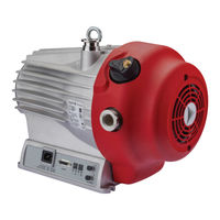
Pfeiffer Vacuum HISCROLL 6 Operating Instructions Manual (160 pages)
Scroll pump with integrated pressure sensor
Brand:
Pfeiffer Vacuum
| Category:
Water Pump
| Size: 21 MB
Table of Contents
Deutsch
3
Telegram Example
1
Telegramm Beispiel
2
Telegram Example
2
Table of Contents
3
Zu dieser Anleitung
8
Gültigkeit
8
Mitgeltende Dokumente
8
Varianten
8
Zielgruppe
8
Konventionen
8
Piktogramme
8
Aufkleber auf dem Produkt
9
Anweisungen IM Text
9
Abb. 1: Position der Aufkleber auf dem Produkt
10
Abkürzungen
11
Sicherheit
12
Allgemeine Sicherheitshinweise
12
Sicherheitshinweise
12
Sicherheitsmaßnahmen
16
Einsatzgrenzen des Produkts
16
Personenqualifikation
17
Vorhersehbarer Fehlgebrauch
17
Bestimmungsgemäße Verwendung
17
Personenqualifikation Sicherstellen
18
Personenqualifikation bei Wartung und Reparatur
18
Mit Pfeiffer Vacuum Weiterbilden
18
Produktbeschreibung
19
Funktion
19
Abb. 2: Schematischer Verdichtungszyklus von Scrollpumpen
19
Abb. 3: Aufbau Hiscroll, Ausführung mit Drucksensor
20
Drucksensor
20
Wellenlager
20
Gasballast
20
Kühlung
20
Antrieb
20
Anschlüsse
21
Produkt Identifizieren
21
Produktmerkmale
21
Lieferumfang
21
Abb. 4: Anschlagpunkte für den Transport der Scrollpumpe
22
Vakuumpumpe Transportieren
22
Transport und Lagerung
22
Vakuumpumpe Lagern
23
Installation
24
Vakuumpumpe Aufstellen
24
Vakuumseite Anschließen
24
Abb. 5: Mindestabstände und Zulässige Neigung
24
Auspuffseite Anschließen
25
Abb. 6: Beispiel für den Vakuumanschluss
25
Externe Gasballastversorgung Anschließen
26
Abb. 7: Beispiel für den Auspuffanschluss
26
Netzanschluss Herstellen
27
Abb. 8: Externe Gasballastversorgung Anschließen
27
Abb. 9: Netzanschluss Herstellen
28
Schnittstellen
29
Schnittstellenübersicht
29
Schnittstelle "Remote
29
Abb. 11: Anschlussdiagramm des 15-Poligen Anschlusses "Remote
29
Ausgänge
30
Eingänge
30
Rs-485
31
Steuergerät Anschließen
31
Schnittstelle RS-485 Verwenden
31
Abb. 12: Anschluss eines Steuergeräts über Anschluss "Remote
31
Pfeiffer Vacuum Protokoll für RS-485-Schnittstelle
32
Telegrammrahmen
32
Telegrammbeschreibung
32
Abb. 13: Vernetzung über Anschluss RS-485 mit Verbindungskabeln und Zubehör
32
Telegramm Beispiel
33
Datentypen
33
Parametersatz
35
Allgemeines
35
Stellbefehle
35
Statusabfragen
37
Sollwertvorgaben
37
Digitalausgänge Konfigurieren
39
Anschlüsse mit dem Pfeiffer Vacuum Parametersatz Konfigurieren
39
Vakuumpumpe Einschalten
39
Vakuumpumpe in Betrieb Nehmen
39
Betrieb
39
Digitaleingang Konfigurieren
40
Schnittstellen Auswählen
40
Zubehör Konfigurieren
40
Betriebsart Auswählen
41
Geschwindigkeitsmodi
41
Drehzahlstellbetrieb
42
Standby-Betrieb
42
Normalbetrieb
42
Auto-Boost
43
Auto-Standby
43
Auto-Start
43
Druckregelbetrieb
43
Effektiven Druck mit Korrekturfaktoren Ermitteln
44
Gasballast Verwenden
45
Gasballastventil mit Drucksensor Steuern
46
Gasballastventil ohne Drucksensor Steuern
47
Betriebsanzeige über LED
48
Vakuumpumpe Ausschalten
48
Wartung
49
Wartungsinformationen
49
Checkliste für Inspektion und Wartung
49
Auspuffseitiges Rückschlagventil Austauschen
50
Rückschlagventil Demontieren
51
Rückschlagventilentil Montieren
51
Gasballastventil Austauschen
52
Gasballastventil Demontieren
52
Gasballastventil Montieren
53
Tip Seal Wechseln
54
Spiralgehäuse Demontieren
54
Tip Seal Austauschen
56
Pumpengehäuse Zusammenbauen
58
Abschlussprüfung
59
Wiederinbetriebnahme
60
Stillsetzen für Längere Zeit
60
Außerbetriebnahme
60
Recycling und Entsorgung
61
Allgemeine Entsorgungshinweise
61
Scrollpumpe Entsorgen
61
Störungen
62
Allgemeines
62
Fehlercodes
63
Warn- und Fehlermeldungen bei Betrieb mit Steuergeräten
64
Servicelösungen von Pfeiffer Vacuum
66
Ersatzteile
68
Zubehör
70
Zubehörinformationen
70
Zubehör Bestellen
70
Technische Daten und Abmessungen
72
Allgemeines
72
Technische Daten
72
Medienberührende Werkstoffe
75
Abmessungen
76
EG Konformitätserklärung
78
Konformitätserklärung
79
English
81
About this Manual
86
Applicable Documents
86
Conventions
86
Pictographs
86
Target Group
86
Validity
86
Variants
86
Instructions in the Text
87
Stickers on the Product
87
Fig. 1: Position of the Stickers on the Product
88
Abbreviations
89
General Safety Information
90
Safety
90
Safety Instructions
90
Limits of Use of Product
94
Safety Precautions
94
Foreseeable Improper Use
95
Personnel Qualification
95
Proper Use
95
Tbl. 2: Permissible Ambient Conditions
95
Advanced Training with Pfeiffer Vacuum
96
Ensuring Personnel Qualification
96
Personnel Qualification for Maintenance and Repair
96
Fig. 2: Schematic Compression Cycle of Scroll Pumps
97
Function
97
Product Description
97
Cooling
98
Drive
98
Fig. 3: Hiscroll Design, Version with Pressure Sensor
98
Gas Ballast
98
Pressure Sensor
98
Shaft Bearing
98
Connections
99
Identifying the Product
99
Product Features
99
Scope of Delivery
99
Tbl. 3: Interfaces of the Electronic Drive Unit
99
Tbl. 4: Features of Scroll Pumps
99
Fig. 4: Slinging Points for Transport of the Scroll Pump
100
Transportation and Storage
100
Transporting Vacuum Pump
100
Storing the Vacuum Pump
101
Connecting Vacuum Side
102
Fig. 5: Minimum Clearances and Permissible Inclination
102
Installation
102
Set up the Vacuum Pump
102
Connecting the Exhaust Side
103
Fig. 6: Example of Vacuum Connection
103
Connecting Gas Ballast External Supply
104
Fig. 7: Example of Exhaust Connection
104
Connecting to Mains Power Supply
105
Fig. 8: Connecting Gas Ballast External Supply
105
Fig. 9: Connecting to Mains Power Supply
106
Fig. 10: Interfaces of the Electronic Drive Unit
107
Fig. 11: Connection Diagram of 15-Pin "Remote" Connection
107
Interface Overview
107
Interfaces
107
Remote" Interface
107
Inputs
108
Outputs
108
Tbl. 5: Connection Assignment of 15-Pin "Remote" Connection
108
Connecting Control Unit
109
Fig. 12: Connecting a Control Unit Via the "Remote" Connection
109
Rs-485
109
Tbl. 6: Features of the RS-485 Interface
109
Using RS-485 Interface
109
Fig. 13: Cross-Link Via Connection RS-485 Using Connection Cables and Accessories
110
Pfeiffer Vacuum Protocol for RS-485 Interface
110
Telegram Frame
110
Telegram Description
111
Data Types
112
Control Commands
113
General
113
Parameter Set
113
Tbl. 7: Explanation and Meaning of the Parameters
113
Reference Value Inputs
115
Status Requests
115
Tbl. 9: Status Requests
115
Configuring the Connections with the Pfeiffer Vacuum Parameter Set
117
Configuring the Digital Outputs
117
Operation
117
Putting the Vacuum Pump into Operation
117
Switch Vacuum Pump on
117
Configuring Accessories
118
Configuring the Digital Input
118
Selecting the Interfaces
118
Tbl. 11: Configure Parameters [P:019] and [P:024]
118
Tbl. 12: Configure Parameter [P:063]
118
Tbl. 13: Parameter [P:060]
118
Fig. 14: Accessory Connector Assignment
119
Selecting Operating Mode
119
Speed Modes
119
Fig. 15: Speed Modes
120
Normal Operation
120
Speed Actuator Operation
120
Standby Mode
120
Auto Boost
121
Auto Standby
121
Auto Start
121
Determining Effective Pressure with Correction Factors
122
Pressure Regulation Operation
122
Tbl. 14: Correction Factor for Pressure Range < 1 Hpa
122
Fig. 16: Displayed Pressure
123
Operation with Gas Ballast
123
Controlling Gas Ballast Valve with a Pressure Sensor
124
Tbl. 15: Hiscroll Gas Ballast Valve Switch Settings
124
Controlling Gas Ballast Valve Without a Pressure Sensor
125
Fig. 17: Pressure-Dependent Gas Ballast Valve Control in Automatic Mode
125
Fig. 18: Gas Ballast Valve Control in Automatic Mode
125
Operating Mode Display Via LED
126
Switching off Vacuum Pump
126
Checklist for Inspection and Maintenance
127
Maintenance
127
Maintenance Information
127
Replacing the Non-Return Valve on the Exhaust Side
128
Fig. 19: Removing Valve
129
Fig. 20: Installing Valve
129
Installing the Non-Return Valve
129
Removing the Non-Return Valve
129
Fig. 21: Removing Gas Ballast Valve
130
Removing Gas Ballast Valve
130
Replacing the Gas Ballast Valve
130
Fig. 22: Removing Gas Ballast Valve
131
Fig. 23: Assemble Gas Ballast Valve
131
Installing Gas Ballast Valve
131
Changing the Tip Seal
132
Disassembling the Spiral Housing
132
Fig. 24: Installing Gas Ballast Valve
132
Fig. 25: Loosening the Fan Cover on the Scroll Pump
133
Fig. 26: Removing the Fan Cover from the Scroll Pump
133
Fig. 27: Removing the Scroll Pump Spiral Housing
134
Replacing the Tip Seal
134
Fig. 28: Replacing the Tip Seal on the Scroll Pump
135
Fig. 29: Tip Seal Nut in the Spiral Housing
135
Assembling the Pump Housing
136
Fig. 30: Assembling the Housing Parts
136
Final Inspection
137
Decommissioning
138
Recommissioning
138
Shutting down for Longer Periods
138
Disposing of the Scroll Pump
139
General Disposal Information
139
Recycling and Disposal
139
General
140
Malfunctions
140
Error Codes
141
Warning and Malfunction Messages When Operating with Control Units
142
Service Solutions by Pfeiffer Vacuum
144
Fig. 31: Hiscroll Maintenance Kit
146
Spare Parts
146
Tbl. 23: Spare Part Package
146
Fig. 32: Hiscroll Valve Set
147
Tbl. 24: Spare Part Package
147
Accessories
148
Accessory Information
148
Ordering Accessories
148
Tbl. 25: Accessories for Hiscroll
149
General
150
Technical Data
150
Technical Data and Dimensions
150
Substances in Contact with the Media
153
Dimensions
154
Fig. 33: Hiscroll 6 | Version with Pressure Sensor
154
EC Declaration of Conformity
156
Declaration of Conformity
157
Advertisement
Pfeiffer Vacuum HISCROLL 6 Operating Instructions Manual (84 pages)
Scroll pump standard version/ATEX certification
Brand:
Pfeiffer Vacuum
| Category:
Water Pump
| Size: 11 MB
Table of Contents
Telegram Example
2
Table of Contents
3
About this Manual
8
Validity
8
Applicable Documents
8
Variants
8
Target Group
8
Conventions
8
Pictographs
8
Instructions in the Text
9
Stickers on the Product
9
Tbl. 1: Stickers on the Product
10
Fig. 1: Position of the Stickers on the Product
10
Abbreviations
11
Safety
12
General Safety Information
12
Safety Instructions
12
Safety Precautions
17
ATEX Classification and Safety Measures
17
Tbl. 3: General ATEX Designations
18
Limits of Use of the Product
19
Proper Use
19
Foreseeable Improper Use
19
Tbl. 4: Permissible Ambient Conditions
19
Personnel Qualification
20
Ensuring Personnel Qualification
20
Personnel Qualification for Maintenance and Repair
20
Advanced Training with Pfeiffer Vacuum
21
Product Description
22
Function
22
Fig. 2: Schematic Compression Cycle of Scroll Pumps
22
Drive
23
Cooling
23
Shaft Bearing
23
Gas Ballast
23
Pressure Sensor
23
Fig. 3: Hiscroll Design
23
Connections
24
Identifying the Product
24
Product Features
24
Scope of Delivery
24
Tbl. 5: Interfaces of the Electronic Drive Unit
24
Tbl. 6: Features of Scroll Pumps
24
Transportation and Storage
25
Transporting Vacuum Pump
25
Fig. 4: Slinging Points for Transport of the Scroll Pump
25
Storing the Vacuum Pump
26
Installation
27
Set up the Vacuum Pump
27
Connecting Vacuum Side
27
Fig. 5: Minimum Clearances and Permissible Inclination
27
Connecting the Exhaust Side
28
Fig. 6: Example of Vacuum Connection
28
Connecting Gas Ballast External Supply
29
Fig. 7: Example of Exhaust Connection
29
Connecting to Mains Power Supply
30
Fig. 8: Connecting Gas Ballast External Supply
30
Fig. 9: Connecting to Mains Power Supply
31
Interfaces
32
Interface Overview
32
Remote" Interface
32
Fig. 10: Interfaces of the Electronic Drive Unit
32
Fig. 11: Connection Diagram of 15-Pin "Remote" Connection
32
Inputs
33
Outputs
33
Tbl. 7: Connection Assignment of 15-Pin "Remote" Connection
33
Rs-485
34
Connecting Control Unit
34
Using RS-485 Interface
34
Tbl. 8: Features of the RS-485 Interface
34
Fig. 12: Connecting a Control Unit Via the "Remote" Connection
34
Pfeiffer Vacuum Protocol for RS-485 Interface
35
Telegram Frame
35
Fig. 13: Cross-Link Via Connection RS-485 Using Connection Cables and Accessories
35
Telegram Description
36
Telegram Example
36
Data Types
37
Parameter Set
38
General
38
Control Commands
38
Tbl. 9: Explanation and Meaning of the Parameters
38
Status Requests
40
Reference Value Inputs
40
Tbl. 11: Status Requests
40
Operation
42
Commissioning Vacuum Pump
42
Switch Vacuum Pump on
42
Configuring the Connections with the Pfeiffer Vacuum Parameter Set
42
Configuring the Digital Outputs
43
Configuring the Digital Input
43
Selecting the Interfaces
43
Configuring Accessories
43
Tbl. 13: Configure Parameters [P:019] and [P:024]
43
Tbl. 14: Configure Parameter [P:063]
43
Tbl. 15: Parameter [P:060]
43
Selecting Operating Mode
44
Speed Modes
44
Fig. 14: Accessory Connector Assignment
44
Normal Operation
45
Standby Mode
45
Speed Actuator Operation
45
Fig. 15: Speed Modes
45
Auto Boost
46
Auto Standby
46
Pressure Regulation Operation
47
Determining Effective Pressure with Calibration Factors
47
Tbl. 16: Calibration Factors for the Pressure Range < 1 Hpa
47
Operating with Gas Ballast
48
Fig. 16: Displayed Pressure
48
Tbl. 17: Hiscroll Gas Ballast Valve Switch Settings
49
Controlling Gas Ballast Valve with a Pressure Sensor
50
Controlling Gas Ballast Valve Without a Pressure Sensor
50
Fig. 17: Pressure-Dependent Gas Ballast Valve Control in Automatic Mode
50
Fig. 18: Gas Ballast Valve Control in Automatic Mode
50
Operating Mode Display Via LED
51
Switching off Vacuum Pump
51
Maintenance
53
Maintenance Information
53
Checklist for Inspection and Maintenance
54
Replacing the Non-Return Valve on the Exhaust Side
54
Removing the Non-Return Valve
55
Installing the Non-Return Valve
55
Fig. 19: Removing Valve
55
Fig. 20: Installing Valve
55
Replacing the Gas Ballast Valve
56
Removing Gas Ballast Valve
56
Fig. 21: Removing Gas Ballast Valve
56
Installing Gas Ballast Valve
57
Fig. 22: Removing Gas Ballast Valve
57
Fig. 23: Assemble Gas Ballast Valve
57
Changing the Tip Seal
58
Disassembling the Spiral Housing
58
Fig. 24: Installing Gas Ballast Valve
58
Fig. 25: Loosening the Fan Cover on the Scroll Pump
59
Fig. 26: Removing the Fan Cover from the Scroll Pump
59
Replacing the Tip Seal
60
Fig. 27: Removing the Scroll Pump Spiral Housing
60
Fig. 28: Replacing the Tip Seal on the Scroll Pump
61
Fig. 29: Tip Seal Nut in the Spiral Housing
61
Assembling the Pump Housing
62
Fig. 30: Assembling the Housing Parts
62
Final Inspection
63
Decommissioning
64
Shutting down for Longer Periods
64
Recommissioning
64
Recycling and Disposal
65
General Disposal Information
65
Disposing of the Scroll Pump
65
Malfunctions
66
General
66
Error Codes
67
Service Solutions by Pfeiffer Vacuum
69
Spare Parts
71
Tbl. 24: Spare Part Package
71
Fig. 31: Hiscroll Maintenance Kit
71
Tbl. 25: Spare Part Package
72
Fig. 32: Hiscroll Valve Set
72
Accessories
73
Accessory Information
73
Ordering Accessories
73
Tbl. 26: Accessories for Hiscroll
74
Technical Data and Dimensions
75
General
75
Technical Data
75
Substances in Contact with the Media
78
Dimensions
79
Declaration of Conformity
81
Declaration of Conformity
82
Pfeiffer Vacuum HISCROLL 6 Operating Instructions Manual (80 pages)
Scroll pump with integrated pressure sensor
Brand:
Pfeiffer Vacuum
| Category:
Water Pump
| Size: 11 MB
Table of Contents
Telegram Example
2
Table of Contents
3
About this Manual
8
Validity
8
Applicable Documents
8
Variants
8
Target Group
8
Conventions
8
Pictographs
8
Instructions in the Text
9
Stickers on the Product
9
Fig. 1: Position of the Stickers on the Product
10
Abbreviations
11
Safety
12
General Safety Information
12
Safety Instructions
12
Safety Precautions
16
Limits of Use of the Product
16
Proper Use
17
Foreseeable Improper Use
17
Personnel Qualification
17
Tbl. 2: Permissible Ambient Conditions
17
Ensuring Personnel Qualification
18
Personnel Qualification for Maintenance and Repair
18
Advanced Training with Pfeiffer Vacuum
18
Product Description
19
Function
19
Fig. 2: Schematic Compression Cycle of Scroll Pumps
19
Drive
20
Cooling
20
Shaft Bearing
20
Gas Ballast
20
Pressure Sensor
20
Fig. 3: Hiscroll Design, Version with Pressure Sensor
20
Connections
21
Identifying the Product
21
Product Features
21
Scope of Delivery
21
Tbl. 3: Interfaces of the Electronic Drive Unit
21
Tbl. 4: Features of Scroll Pumps
21
Transportation and Storage
22
Transporting Vacuum Pump
22
Fig. 4: Slinging Points for Transport of the Scroll Pump
22
Storing the Vacuum Pump
23
Installation
24
Set up the Vacuum Pump
24
Connecting Vacuum Side
24
Fig. 5: Minimum Clearances and Permissible Inclination
24
Connecting the Exhaust Side
25
Fig. 6: Example of Vacuum Connection
25
Connecting Gas Ballast External Supply
26
Fig. 7: Example of Exhaust Connection
26
Connecting to Mains Power Supply
27
Fig. 8: Connecting Gas Ballast External Supply
27
Fig. 9: Connecting to Mains Power Supply
28
Interfaces
29
Interface Overview
29
Remote" Interface
29
Fig. 10: Interfaces of the Electronic Drive Unit
29
Fig. 11: Connection Diagram of 15-Pin "Remote" Connection
29
Inputs
30
Outputs
30
Tbl. 5: Connection Assignment of 15-Pin "Remote" Connection
30
Rs-485
31
Connecting Control Unit
31
Using RS-485 Interface
31
Tbl. 6: Features of the RS-485 Interface
31
Fig. 12: Connecting a Control Unit Via the "Remote" Connection
31
Pfeiffer Vacuum Protocol for RS-485 Interface
32
Telegram Frame
32
Fig. 13: Cross-Link Via Connection RS-485 Using Connection Cables and Accessories
32
Telegram Description
33
Telegram Example
33
Data Types
34
Parameter Set
35
General
35
Control Commands
35
Tbl. 7: Explanation and Meaning of the Parameters
35
Status Requests
37
Reference Value Inputs
37
Tbl. 9: Status Requests
37
Operation
39
Putting the Vacuum Pump into Operation
39
Switch Vacuum Pump on
39
Configuring the Connections with the Pfeiffer Vacuum Parameter Set
39
Configuring the Digital Outputs
39
Configuring the Digital Input
40
Selecting the Interfaces
40
Configuring Accessories
40
Tbl. 11: Configure Parameters [P:019] and [P:024]
40
Tbl. 12: Configure Parameter [P:063]
40
Tbl. 13: Parameter [P:060]
40
Selecting Operating Mode
41
Speed Modes
41
Fig. 14: Accessory Connector Assignment
41
Normal Operation
42
Standby Mode
42
Speed Actuator Operation
42
Fig. 15: Speed Modes
42
Auto Boost
43
Auto Standby
43
Pressure Regulation Operation
43
Determining Effective Pressure with Calibration Factors
44
Tbl. 14: Calibration Factors for the Pressure Range < 1 Hpa
44
Operation with Gas Ballast
45
Fig. 16: Displayed Pressure
45
Controlling Gas Ballast Valve with a Pressure Sensor
46
Tbl. 15: Hiscroll Gas Ballast Valve Switch Settings
46
Controlling Gas Ballast Valve Without a Pressure Sensor
47
Fig. 17: Pressure-Dependent Gas Ballast Valve Control in Automatic Mode
47
Fig. 18: Gas Ballast Valve Control in Automatic Mode
47
Operating Mode Display Via LED
48
Switching off Vacuum Pump
48
Maintenance
49
Maintenance Information
49
Checklist for Inspection and Maintenance
49
Replacing the Non-Return Valve on the Exhaust Side
50
Removing the Non-Return Valve
51
Installing the Non-Return Valve
51
Fig. 19: Removing Valve
51
Fig. 20: Installing Valve
51
Replacing the Gas Ballast Valve
52
Removing Gas Ballast Valve
52
Fig. 21: Removing Gas Ballast Valve
52
Installing Gas Ballast Valve
53
Fig. 22: Removing Gas Ballast Valve
53
Fig. 23: Assemble Gas Ballast Valve
53
Changing the Tip Seal
54
Disassembling the Spiral Housing
54
Fig. 24: Installing Gas Ballast Valve
54
Fig. 25: Loosening the Fan Cover on the Scroll Pump
55
Fig. 26: Removing the Fan Cover from the Scroll Pump
55
Replacing the Tip Seal
56
Fig. 27: Removing the Scroll Pump Spiral Housing
56
Fig. 28: Replacing the Tip Seal on the Scroll Pump
57
Fig. 29: Tip Seal Nut in the Spiral Housing
57
Assembling the Pump Housing
58
Fig. 30: Assembling the Housing Parts
58
Final Inspection
59
Decommissioning
60
Shutting down for Longer Periods
60
Recommissioning
60
Recycling and Disposal
61
General Disposal Information
61
Disposing of the Scroll Pump
61
Malfunctions
62
General
62
Error Codes
63
Warning and Malfunction Messages When Operating with Control Units
64
Service Solutions by Pfeiffer Vacuum
66
Spare Parts
68
Tbl. 23: Spare Part Package
68
Fig. 31: Hiscroll Maintenance Kit
68
Tbl. 24: Spare Part Package
69
Fig. 32: Hiscroll Valve Set
69
Accessories
70
Accessory Information
70
Ordering Accessories
70
Tbl. 25: Accessories for Hiscroll
71
Technical Data and Dimensions
72
General
72
Technical Data
72
Substances in Contact with the Media
75
Dimensions
76
Fig. 33: Hiscroll 6 | Version with Pressure Sensor
76
Declaration of Conformity
78
Declaration of Conformity
79
Advertisement
Pfeiffer Vacuum HISCROLL 6 Translation Of The Original (66 pages)
Scroll pump
Brand:
Pfeiffer Vacuum
| Category:
Water Pump
| Size: 5 MB
Table of Contents
Telegram Example
2
Table of Contents
3
1 About this Manual
8
Validity
8
Applicable Documents
8
Variants
8
Target Group
8
Conventions
8
Pictographs
8
Instructions in the Text
8
Stickers on the Product
9
Tbl. 1: Stickers on the Product
9
Abbreviations
10
Tbl. 2: Abbreviations Used
10
Fig. 1: Position of the Stickers on the Product
10
2 Safety
11
General Safety Information
11
Safety Instructions
11
Safety Precautions
15
Limits of Use of the Product
16
Proper Use
16
Foreseeable Misuse
16
Tbl. 3: Permissible Ambient Conditions
16
Personnel Qualification
17
Ensuring Personnel Qualification
17
Personnel Qualification for Maintenance and Repair
17
Advanced Training with Pfeiffer Vacuum
18
3 Product Description
19
Function
19
Fig. 2: Schematic Compression Cycle of Scroll Pumps
19
Cooling
20
Drive
20
Fig. 3: Hiscroll Design
20
Gas Ballast
20
Pressure Sensor
20
Shaft Bearing
20
Connections
21
Identifying the Product
21
Product Features
21
Scope of Delivery
21
Tbl. 4: Interfaces of the Electronic Drive Unit
21
Tbl. 5: Features of Scroll Pumps
21
4 Transportation and Storage
22
Transporting the Vacuum Pump
22
Fig. 4: Slinging Points for Transport of the Scroll Pump
22
Storing the Vacuum Pump
23
5 Installation
24
Set up the Vacuum Pump
24
Connecting the Vacuum Side
24
Fig. 5: Minimum Clearances and Permissible Inclination
24
Connecting the Exhaust Side
25
Fig. 6: Example of Vacuum Connection
25
Connecting the External Gas Ballast Supply
26
Fig. 7: Example of Exhaust Connection
26
Establishing the Mains Connection
27
Fig. 8: Connecting the Gas Ballast External Supply
27
Fig. 9: Establishing Mains Connection
28
6 Interfaces
29
Interface Overview
29
Remote" Interface
29
Fig. 10: Interfaces of the Electronic Drive Unit
29
Fig. 11: Connection Diagram of 15-Pin "Remote" Connection
29
Inputs
30
Outputs
30
Tbl. 6: Terminal Lay-Out of 15-Pin "Remote" Connection
30
Rs-485
31
Connection Options
31
Interface RS-485
31
Fig. 12: Connecting a Display and Control Unit Via "Remote
31
Pfeiffer Vacuum Protocol for RS-485 Interface
32
Telegram Frame
32
Fig. 13: Cross-Link Via Connection RS-485 Using Connection Cables and Accessories
32
Telegram Description
33
Telegram Example
33
Data Types
34
7 Parameter Set
35
General
35
Control Commands
35
Tbl. 8: Explanation and Meaning of the Parameters
35
Status Requests
36
Reference Value Inputs
37
Tbl. 10: Status Requests
37
Tbl. 11: Reference Value Inputs
37
Additional Parameter for the DCU
38
8 Operation
39
Putting the Vacuum Pump into Operation
39
Switching on the Vacuum Pump
39
Configuring the Connections with the Pfeiffer Vacuum Parameter Set
39
Configuring the Digital Outputs
39
Selecting the Interfaces
40
Operating Modes
40
Tbl. 13: Configure Parameters [P:019] and [P:024]
40
Tbl. 14: Parameter [P:060]
40
Speed Modes
41
Normal Operation
41
Standby Mode
41
Fig. 14: Speed Modes
41
Speed Actuator Operation
42
Auto Boost
42
Auto Standby
42
Pressure Regulation Operation
43
Operation with Gas Ballast
43
Operating Mode Display Via LED
44
Tbl. 15: Hiscroll Gas Ballast Valve Switch Settings
44
Tbl. 16: Behavior and Meaning of the LEDS of the Electronic Drive Unit
44
Switching off the Vacuum Pump
45
Tbl. 17: Behavior and Meaning of the LED Standby
45
9 Maintenance
46
Maintenance Information
46
Checklist for Inspection and Maintenance
46
Changing the Tip Seal
47
Disassembling the Spiral Housing
47
Fig. 15: Loosening the Fan Cover on the Scroll Pump
48
Fig. 16: Removing the Fan Cover on the Scroll Pump
48
Replacing the Tip Seal
49
Fig. 17: Removing the Scroll Pump Spiral Housing
49
Fig. 18: Replacing the Tip Seal on the Scroll Pump
50
Fig. 19: Tip Seal Nut in the Spiral Housing
50
Assembling the Pump Housing
51
Fig. 20: Assembling the Housing Parts
51
10 Decommissioning
53
Shutting down for Longer Periods
53
Recommissioning
53
11 Recycling and Disposal
54
General Disposal Information
54
Disposing of the Scroll Pump
54
12 Malfunctions
55
General
55
Error Codes
56
Tbl. 19: Troubleshooting with Scroll Pumps
56
Warning and Error Messages When Operating with DCU
57
13 Service Solutions by Pfeiffer Vacuum
58
14 Accessories
60
Accessory Information
60
Ordering Accessories
60
Tbl. 23: Accessories for Hiscroll
60
15 Technical Data and Dimensions
61
General
61
Technical Data
61
Tbl. 26: Technical Data for Hiscroll
62
Substances in Contact with the Media
63
Fig. 21: Hiscroll 12 | Hiscroll
64
Advertisement
Related Products
Pfeiffer Vacuum HILOBE 6204
Pfeiffer Vacuum HiLobe 6204 H
Pfeiffer Vacuum DUO 65
Pfeiffer Vacuum DUO 65 C
Pfeiffer Vacuum DUO 65 MC
Pfeiffer Vacuum HISCROLL 12
Pfeiffer Vacuum HISCROLL 18
Pfeiffer Vacuum HISCROLL 46
Pfeiffer Vacuum HiPace 60 P
Pfeiffer Vacuum Classic 600 G
Pfeiffer Vacuum Categories
Water Pump
Control Unit
Measuring Instruments
Industrial Equipment
Security Sensors
More Pfeiffer Vacuum Manuals
Login
Sign In
OR
Sign in with Facebook
Sign in with Google
Upload manual
Upload from disk
Upload from URL