
Related Manuals for Pfeiffer Vacuum HICUBE ECO


Summary of Contents for Pfeiffer Vacuum HICUBE ECO
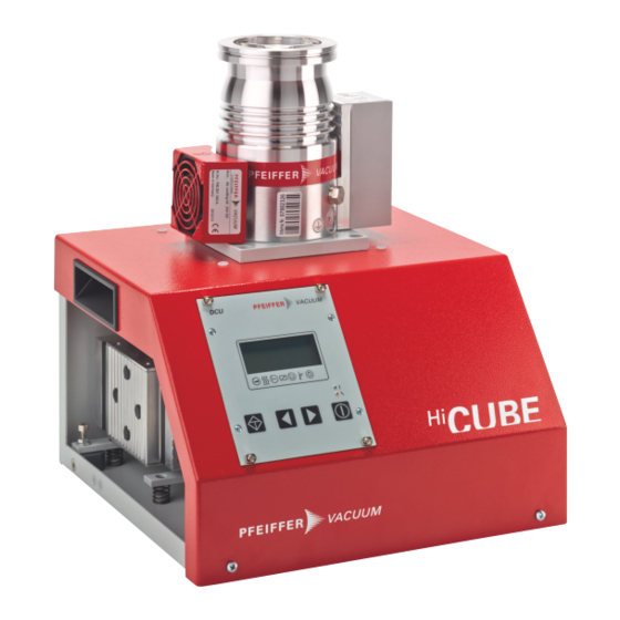
- Page 1 OPERATING INSTRUCTIONS Translation of the Original HICUBE ECO Turbo pumping stations...
- Page 2 PT0553BEN_C PT0553 2017-08-03...
-
Page 3: Table Of Contents
Table of contents Table of contents About this manual Validity 1.1.1 Related documents 1.1.2 Variants Target group Conventions 1.3.1 Abbreviations 1.3.2 Pictographs 1.3.3 Stickers on the product 1.3.4 Instructions in the text Safety General safety instructions Safety instructions Safety precautions Limits of use of the product Proper use Foreseeable misuse... - Page 4 7.3.1 Dismantling connections 7.3.2 Removing the turbopump Decommissioning Shutting down for longer periods Recommissioning Disposal Malfunctions General Troubleshooting Error codes Service solutions from Pfeiffer Vacuum Accessories Technical data and dimensions 12.1 General 12.2 Technical Data 12.3 Dimensioned drawings Declaration of Conformity 4/56...
-
Page 5: About This Manual
Keep the manual for future consultation. 1.1 Validity These operating instructions are for customers of Pfeiffer Vacuum. They describe the function of the designated product and provide the most important information for a safe usage of the product. The de- scriptions comply with applicable directives. All information provided in these operating instructions refer to the current development status of the product. -
Page 6: Pictographs
About this manual Abbreviation Meaning in the document Display: Liquid crystal (LCD) Illuminating diode Diaphragm vacuum pump Protective earth [P:xxx] Control parameters of the electronic drive unit Printed in bold as a three-digit number in square brackets. Frequently displayed in combination with a short designation. Example: [P:312] Software version Temperature (in °C) Electronic drive unit of the turbopump (turbo controller) -
Page 7: Instructions In The Text
About this manual Warning of electrical voltage The sticker warns of the risk of electric shock when working with the housing open. Imperative: Disconnect the mains plug The sticker instructs the disconnection of the mains plug from the equipment before installa- tion, servicing and maintenance work. -
Page 8: Safety
Safety 2 Safety 2.1 General safety instructions This document includes the following four risk levels and one information level. DANGER Imminent danger Indicates a hazardous situation which, if not avoided, will result in death or serious injury. ► Instructions on avoiding the hazardous situation WARNING Possibly imminent danger Indicates a hazardous situation which, if not avoided, could result in death or serious injury. - Page 9 When conveying gases with non-permissibly high molecule masses, there is a risk of the turbopump being destroyed. ► Make sure the gas mode is set correctly [P:027] on the electronic drive unit. ► Consult Pfeiffer Vacuum before using gases with larger molecule gases (> 80). 9/56...
- Page 10 ► Observe the prescribed maximum pressure rise speed of 15 hPa/s. ► Avoid manual and uncontrolled venting of very low volumes. ► Where necessary, use a venting valve from the Pfeiffer Vacuum range of accessories. Risks during maintenance WARNING Danger of death from electric shock during servicing and maintenance work The device is only free of voltage with the mains plug disconnected and the turbopump at a standstill.
-
Page 11: Safety Precautions
► Follow the installation instructions from the manufacturer. ► Observe the requirements for stability and the design of the counter flange. ► Only use approved original accessories or mounting elements approved by Pfeiffer Vacuum for the installation process. WARNING... -
Page 12: Limits Of Use Of The Product
Safety 2.4 Limits of use of the product Parameters Limit values Installation location Weather-protected (interior spaces) Air pressure 750 hPa to 1060 hPa Installation altitude max. 2000 m Relative humidity max. 80 %, at T < 31 °C max. 50 % at T < 40 °C Protection class Overvoltage category Protection rating (IP code) - Page 13 Safety ● Use in areas with ionizing radiation ● Operation in explosion-hazard areas ● Use in systems in which impact loads and vibrations or periodic forces are exerted on the equip- ment ● Use of accessories or spare parts that are not described in this manual 13/56...
-
Page 14: Transportation And Storage
Protective cover Installation base Notes on safe transportation without packaging For transport without packaging, the HiCube Eco turbo pumping stations are equipped with recessed handles on the side of the housing frame. 1. Observe the weight specified on the rating plate. -
Page 15: Storage
Transportation and Storage 3.3 Storage Pfeiffer Vacuum recommends storing the products in their original transport pack- aging. Storing the pumping station 1. Seal the flange openings using the original protective covers. 2. Seal other connections (e.g. exhaust) with appropriate protective covers. -
Page 16: Product Description
Information on certifications can be found on the test seal on the product, as applicable, or from: ● www.tuvdotcom.com ● with the company ID no. 000021320 Fig. 2: HiCube Eco pump configuration Characteristics HiCube Eco Operating manual HV flange DN 40 / DN 63... -
Page 17: Function
Tbl. 3: HiCube Eco configuration of vacuum pumps and accessories 4.2 Function Turbo pumping stations are fully automatic pump units supplied ready for connection. A turbo pumping station consists of a portable or mobile vacuum pumping unit with a turbo pump and a specially match- ed backing pump. -
Page 18: Drive
● Water cooling (optional) At excessively high temperatures, the electronic drive unit automatically reduces the drive power. 4.3 Scope of delivery ● HiCube Eco ● Protective cover for high vacuum flange ● Extension cable M12 on M12, 3 m ● Power supply cable, country-specific ●... -
Page 19: Installation
Installation 5 Installation The rotor of the turbopump revolves at very high speed. In practice it is not possible to exclude the risk of the rotor touching the stator (e.g. due to the penetration of foreign bodies into the high vacuum con- nection). -
Page 20: Grounding The Pumping Station
Fig. 5: Example grounding terminal for a HiCube 80 Eco Connecting the grounding Pfeiffer Vacuum recommends connecting an appropriate grounding cable to divert applicative interfer- ence forces. 1. Use the grounding terminal of the turbopump (M4 internal thread). 2. Perform the connection in accordance with applicable local regulations. -
Page 21: Connecting The High Vacuum Side
Tbl. 4: Requirements for the design of the high vacuum connection at the customer's site ► Only use the approved mounting kits from Pfeiffer Vacuum for the high vacuum connection of the turbopump. 5.3.2 Using accessories for the high vacuum connection Installation and operation of accessories Pfeiffer Vacuum offers a range of specially coordinated accessories for its products. -
Page 22: Connecting An External Turbopump
1. Observe the installation notes for the turbopump in the relevant operating instructions for the indi- vidual component. 2. Use cable set PM 071 477 -T (3 m) from the Pfeiffer Vacuum accessories range and extend the fore-vacuum line and the control cable. -
Page 23: Installation Of Iso-K Flange Onto Iso-K
Installation Connection using a clamping ring 1. Only use the approved fastening sets from Pfeiffer Vacuum for the connection. 2. Fasten the high vacuum connection on the turbopump and the clamping ring to the counter flange. 3. Use all prescribed components for the turbopump. - Page 24 Installation Connection of claw and threaded hole 1. Only use the approved fastening sets from Pfeiffer Vacuum for the connection. 2. Connect the flange according to the diagram using the components in the mounting kit. 3. Use all prescribed components for the turbopump.
-
Page 25: Installation Of Cf Flanges
Installation Connection of stud screw and throughbore 1. Only use the approved fastening sets from Pfeiffer Vacuum for the connection. 2. Place the collar flange over the high vacuum flange on the turbopump. 3. Insert the snap ring into the side groove on the high vacuum flange of the turbopump. -
Page 26: Connecting The Exhaust Side
Installation Stud screw and threaded hole 1. Only use the approved mounting kits from Pfeiffer Vacuum for the connection. 2. Screw the required number of stud screws with the shorter screw-in end into the holes in the counter flange. 3. If used: Insert the protective screen or splinter shield with the clamping lugs pointing downward into the high vacuum flange. -
Page 27: Use Of The Dcu As A Remote Control
Installation CAUTION Risk of injury from bursting due to high pressure in the exhaust line Faulty or insufficient exhaust lines cause hazardous situations, e.g. increase in exhaust pressure. There is a risk of bursting. It is not possible to rule out the risk of injuries due to broken pieces flying around, high escaping pressure and damage to the equipment. -
Page 28: Connecting Accessories For The Pumping Station
● Information on approved accessories can be found at pfeiffer-vacuum.com. Accessory connection for TC 110 electronic drive unit ● The use of Pfeiffer Vacuum accessories via the TC 110 electronic drive unit is only possible using the corresponding connection cable and/or adapter on the X3 multi-functional connection. -
Page 29: Unfastening The Transport Retainer
2. Use the Pfeiffer Vacuum display and control unit DCU 002. 5.7 Unfastening the transport retainer All turbo pumping stations in the HiCube Eco range are equipped with a transport retainer for the back- ing pumps (see sticker). The backing pump is fixed diagonally to the pumping station baseplate on 2 spring-mounted rails by 2 cheesehead bolts with nuts. - Page 30 Installation 2. Always ensure a safe connection to the protective conductor (PE). 3. Plug the mains cable provided into the connecting socket on the side of the pumping station hous- ing. 4. Connect the mains cable to the mains supply at the operator's site. 30/56...
-
Page 31: Operation
Pfeiffer Vacuum display and control units or via RS-485 with the Pfeiffer Vacuum proto- col. The DCU is used for both parameter sets as a user interface. The HiCube Eco controls two independ- ent parameter sets for the turbopump and the backing pump. The parameters of the backing pump are shown in order on the display and are identified with a symbol. -
Page 32: Switching On The Turbo Pumping Station
► Switch on the turbo pumping station. 6.3 Operating mode of the turbo pumping station Using the DCU 1. When using the Pfeiffer Vacuum DCU 002 display and control unit, observe the corresponding op- erating manual supplied. Parameter | use Description... -
Page 33: Monitoring The Operating Status
Open the gas ballast valve manually with the MVP 0152 The HiCube Eco turbo pumping station with diaphragm pump MVP 015-2 as the backing pump is equip- ped with an automatic gas ballast function. If delays in the startup time still occur due to condensate in the fore-vacuum range, Pfeiffer Vacuum recommends opening the gas ballast valve manually. -
Page 34: Temperature Monitoring
This causes mechanical damage to the turbopump, including potential failure. ► Observe the prescribed maximum pressure rise speed of 15 hPa/s. ► Avoid manual and uncontrolled venting of very low volumes. ► Where necessary, use a venting valve from the Pfeiffer Vacuum range of accessories. 34/56... - Page 35 General notes for rapid venting Pfeiffer Vacuum recommends performing the rapid venting of larger volumes in 2 stages. 1. Use a Pfeiffer Vacuum venting valve for the turbopump or match the valve cross-section to the size of the recipient and the maximum flow rate.
-
Page 36: Maintenance
2. Clean the pumping station externally with a lint-free cloth cloth and a little industrial alcohol. 3. Clarify shorter maintenance intervals for extreme loads or contaminated processes with Pfeiffer Vacuum Service. 4. For all other cleaning, maintenance or repair work, please contact your Pfeiffer Vacuum service point. 7.3 Removal of components for their maintenance Maintenance work performed by the customer on the pumping station's components may require the components to be removed from the pumping station frame. -
Page 37: Dismantling Connections
1. Remove the connector from the multi-functional connection on the electronic drive unit of the tur- bopump. 2. Unfasten and remove the accessories control cables from the connector. 7.3.2 Removing the turbopump Fig. 14: HiCube Eco | Dismantling the turbopump Mounting plate Fore-vacuum connection Turbopump, complete Fore-vacuum line Retaining bolt with washer 1. - Page 38 Maintenance – Tightening torque of the retaining bolts during subsequent assembly: 10 Nm. 4. Remove the entire turbopump with mounting plate from the frame. The opening in the mounting plate makes it easy for customers to perform mainte- nance work on the turbopump (e.g. change the lubricant reservoir). 38/56...
-
Page 39: Decommissioning
2. Clean the pumping station externally with a lint-free cloth cloth and a little industrial alcohol. 3. Have the pumping station thoroughly cleaned by Pfeiffer Vacuum Service as necessary. 4. Have the pumping station components serviced by Pfeiffer Vacuum Service as necessary. -
Page 40: Malfunctions
Error (** Error E––– **) always result in the shutdown of the connected peripheral devices. Warnings (* Warning F––– *) are only displayed and do not result in the shutdown of components. Handling of error messages on the HiCube Eco 1. First eliminate the cause of the error. - Page 41 Display Problem Possible causes Remedy E698 Communication ● Electronic drive unit not responding ● Contact Pfeiffer Vacuum Service. error ● Transmitter faulty ● Restart with connected measuring tube F110 Pressure gauge ● Connection to the transmitter discon- ● Replace the pressure measuring tube ●...
- Page 42 Display Problem Possible causes Remedy E111 Operating materials pump ● Call Pfeiffer Vacuum Service communication error ● Only acknowledge for rotational speed f = 0 ● Call Pfeiffer Vacuum Service E112 Operating materials pump ● Only acknowledge for rotational speed f = 0...
- Page 43 Tbl. 12: Error and warning messages for the drive electronics of the turbopump Display Problem Possible causes Remedy ● Call Pfeiffer Vacuum Service E042 Software inconsistent Checksum error E091 Hardware unknown ● Call Pfeiffer Vacuum Service ● Call Pfeiffer Vacuum Service...
-
Page 44: Service Solutions From Pfeiffer Vacuum
Our intention is always to optimize our core expertise, servicing vacuum components. After the pur- chase of a product from Pfeiffer Vacuum, our service is still far from over. Often that's precisely where it starts. Naturally with proven Pfeiffer Vacuum quality. - Page 45 ERKLÄRUNG KONTAMINIERUNG Then send your product to your local Service Center. You will receive a confirmation message from Pfeiffer Vacuum. For all service orders, our General Terms and Conditions of Sales and Supply General Terms and Conditions of Repair and Maintenance apply to vacuum equipment and components.
-
Page 46: Accessories
Accessories 11 Accessories Please note the lists of accessories for the individual components in the corre- sponding operating manuals or online at pfeiffer-vacuum.com. 46/56... -
Page 47: Technical Data And Dimensions
Technical data and dimensions 12 Technical data and dimensions 12.1 General This section describes the basic technical specifications on Pfeiffer Vacuum turbopumps. Maximum values refer exclusively to the input as a single load. ● Specifications according to the PNEUROP Committee PN5 ● ISO 27892 2010:"Vacuum technology - Turbomolecular pumps. Measurement of rapid shutdown torque"... - Page 48 Technical data and dimensions Ultimate pressure < 1 · 10 < 1 · 10 < 1 · 10 Pumping speed for N 22 l/s 22 l/s 22 l/s Pumping speed backing pump at 50 Hz 1 m³/h 0.75 m³/h 1.8 m³/h Pump-down time for vacuum chamber 56 s 84 s...
- Page 49 Technical data and dimensions Pumping speed backing pump at 50 Hz 1 m³/h 0.75 m³/h 1.8 m³/h Pump-down time for vacuum chamber 56 s 84 s 15 s size 1 l Pump-down time for vacuum chamber 560 s 836 s 145 s size 10 l Pump-down time for vacuum chamber...
- Page 50 Technical data and dimensions Pump-down time for vacuum chamber 557 s 834 s 143 s size 10 l Pump-down time for vacuum chamber 5572 s 8335 s 1428 s size 100 l Mains requirement: voltage 100 – 240 V 100 – 240 V 100 –...
- Page 51 Technical data and dimensions Pump-down 55 s 83 s 14 s 55 s 83 s 14 s time for vac- uum chamber size 1 l Pump-down 553 s 830 s 138 s 553 s 830 s 138 s time for vac- uum chamber size 10 l Pump-down...
-
Page 52: Dimensioned Drawings
Technical data and dimensions Mains re- 100 – 240 V 100 – 240 V 100 – 240 V 100 – 240 V 100 – 240 V 100 – 240 V quirement: voltage Mains re- 50/60 Hz 50/60 Hz 50/60 Hz 50/60 Hz 50/60 Hz 50/60 Hz... - Page 53 Technical data and dimensions Fig. 17: Dimensions of HiCube 30 Eco, DN 63 ISOK Fig. 18: Dimensions of HiCube 80 Eco, DN 40 ISOKF Fig. 19: Dimensions of HiCube 80 Eco, DN 63 CFF 53/56...
- Page 54 Technical data and dimensions Fig. 20: Dimensions of HiCube 80 Eco, DN 63 ISOK Fig. 21: Dimensions of HiCube 300 Eco, DN 100 CFF Fig. 22: Dimensions of HiCube 300 Eco, DN 100 ISOK 54/56...
-
Page 55: Declaration Of Conformity
Authority for compiling the technical documents rests with Mr. Helmut Bernhardt, Pfeiff- er Vacuum GmbH, Berliner Straße 43, 35614 Aßlar. Turbo pumping station HiCube Eco Harmonized standards and national standards and specifications which have been applied: DIN EN ISO 12100:2011...
Need help?
Do you have a question about the HICUBE ECO and is the answer not in the manual?
Questions and answers