Pfeiffer Vacuum HISCROLL 6 Operating Instructions Manual
Scroll pump standard version/atex certification
Hide thumbs
Also See for HISCROLL 6:
- Translation of the original (66 pages) ,
- Operating instructions manual (80 pages) ,
- Operating instructions manual (160 pages)

Related Manuals for Pfeiffer Vacuum HISCROLL 6


Summary of Contents for Pfeiffer Vacuum HISCROLL 6
- Page 1 OPERATING INSTRUCTIONS Translation of the Original HISCROLL 6 | 12 | 18 Scroll pump standard version | ATEX certification...
-
Page 2: Telegram Example
Dear Customer, Thank you for choosing a Pfeiffer Vacuum product. Your new scroll pump is designed to support you with its performance, perfect operation and without impacting your individual application. The name Pfeiffer Vacuum stands for high-quality vacuum technology, a comprehensive and complete range of top-quality products and first-class service. -
Page 3: Table Of Contents
Limits of use of the product Proper use Foreseeable improper use Personnel qualification 2.8.1 Ensuring personnel qualification 2.8.2 Personnel qualification for maintenance and repair 2.8.3 Advanced training with Pfeiffer Vacuum Product description Function 3.1.1 Drive 3.1.2 Cooling 3.1.3 Shaft bearing 3.1.4 Gas ballast... - Page 4 Status requests Reference value inputs Operation Commissioning vacuum pump Switch vacuum pump on Configuring the connections with the Pfeiffer Vacuum parameter set 8.3.1 Configuring the digital outputs 8.3.2 Configuring the digital input 8.3.3 Selecting the interfaces 8.3.4 Configuring accessories Selecting operating mode Speed modes 8.5.1 Normal operation...
- Page 5 Table of contents Service solutions by Pfeiffer Vacuum Spare parts Accessories 15.1 Accessory information 15.2 Ordering accessories Technical data and dimensions 16.1 General 16.2 Technical data 16.3 Substances in contact with the media 16.4 Dimensions Declaration of Conformity UK Declaration of Conformity...
- Page 6 Accessories for HiScroll Tbl. 27: Conversion table: Pressure units Tbl. 28: Conversion table: Units for gas throughput Tbl. 29: Technical data for HiScroll 6 Tbl. 30: Technical data for HiScroll 12 Tbl. 31: Technical data for HiScroll 18 Tbl. 32:...
- Page 7 Replacing the tip seal on the scroll pump Fig. 29: Tip seal nut in the spiral housing Fig. 30: Assembling the housing parts Fig. 31: HiScroll maintenance kit 1 Fig. 32: HiScroll valve set Fig. 33: HiScroll 6 Fig. 34: HiScroll 12 | HiScroll 18 7/84...
-
Page 8: About This Manual
Keep the manual for future consultation. 1.1 Validity This operating instructions is a customer document of Pfeiffer Vacuum. The operating instructions de- scribe the functions of the named product and provide the most important information for the safe use of the device. The description is written in accordance with the valid directives. The information in this op- erating instructions refers to the product's current development status. -
Page 9: Instructions In The Text
3..1.3.3 Stickers on the product This section describes all the stickers on the product along with their meanings. Rating plate, HiScroll 6 The rating plate is located clearly visible on a longitudinal side of D-35614 Asslar Berliner Str. 43 the vacuum pump. -
Page 10: Tbl. 1: Stickers On The Product
About this manual Rating plate, HiScroll 18 The rating plate is located clearly visible on a longitudinal side of D-35614 Asslar Berliner Str. 43 the vacuum pump. Mod. HiScroll 18 P/N PD S30 000 S/N - - - - - - - - ) max. -
Page 11: Abbreviations
About this manual 1.3.4 Abbreviations Abbreviation Explanation ATEX ATmosphères EXplosibles Atmospheric pressure Operating instructions Rotation speed value of a vacuum pump (frequency, in rpm or Hz) Fluorinated rubber Gas ballast High vacuum [P:xxx] Parameters are printed in bold as three-digit numbers in square brackets. Example: [P:xxx] Software version Personal computer PTFE... -
Page 12: Safety
Safety 2 Safety 2.1 General safety information The following 4 risk levels and 1 information level are taken into account in this document. DANGER Immediately pending danger Indicates an immediately pending danger that will result in death or serious injury if not observed. ►... - Page 13 Safety Risks during installation DANGER Danger to life from electric shock Inadequate or incorrect grounding of the unit leads to contact-sensitive voltage on the housing. When making contact, increased leakage currents will cause a life-threatening electric shock. ► Before the installation, check that the connection leads are voltage-free. ►...
- Page 14 Safety WARNING Risk of fatal injury due to electric shock on account of incorrect installation The device's power supply uses life-threatening voltages. Unsafe or improper installation can lead to life-threatening situations from electric shocks obtained from working with or on the unit. ►...
- Page 15 Safety WARNING Danger of poisoning due to toxic process media escaping from the exhaust pipe During operation with no exhaust line, the vacuum pump allows exhaust gases and vapors to escape freely into the air. There is a risk of injury and fatality due to poisoning in processes with toxic process media.
- Page 16 Safety Risks during maintenance WARNING Risk of injury from reactive, potentially explosive, or otherwise hazardous gas/air mixtures during maintenance Uncontrolled leakage of process gases may result in the formation of explosive gas-air mixtures after opening the vacuum pump. Ignition can cause very serious injuries. ►...
-
Page 17: Safety Precautions
Safety CAUTION Danger of burns on hot surfaces in case of malfunctions Failure of the ventilation due to transport damage or disregarded previous damage lead to impermis- sibly high temperatures. There is a danger of burns by accidental contact. There is a risk of property damage to, and even destruction of the vacuum pump. -
Page 18: Tbl. 3: General Atex Designations
Safety Classification Description Device group Devices which can be used for applications in potentially explosive atmospheres are divided into two groups: Device group I: Devices for mines susceptible to firedamp (will not be discussed in any more detail here) Device group II: Devices for all other potentially explosive areas with the excep- tion of underground operations in mines and their surface installations which are susceptible to hazardous firedamp and / or combustible dust. -
Page 19: Limits Of Use Of The Product
Safety 2.5 Limits of use of the product Installation location Interiors, protected against the accumulation of dust and weather influences, in a non-explosive, dry environment Air pressure 750 hPa to 1060 hPa Installation altitude max. 2500 m Recommended constant intake pressure 200 hPa Installation surface flatness ±10 %... -
Page 20: Personnel Qualification
2.8.2 Personnel qualification for maintenance and repair Advanced training courses Pfeiffer Vacuum offers advanced training courses to maintenance levels 2 and 3. Adequately trained individuals are: ● Maintenance level 1 ─ Customer (trained specialist) ●... -
Page 21: Advanced Training With Pfeiffer Vacuum
Safety 2.8.3 Advanced training with Pfeiffer Vacuum For optimal and trouble-free use of this product, Pfeiffer Vacuum offers a comprehensive range of courses and technical trainings. For more information, please contact Pfeiffer Vacuum technical training. 21/84... -
Page 22: Product Description
3 Product description 3.1 Function The Pfeiffer Vacuum scroll pump is a vacuum pump operating dry in a suction chamber for generating a coarse or medium vacuum according to the physical pumping principle of a spiral vacuum pump. The pump is equipped with an integrated drive and control unit. A three-stage gas ballast system supports the prevention of condensation accumulating in the vacuum pump. -
Page 23: Drive
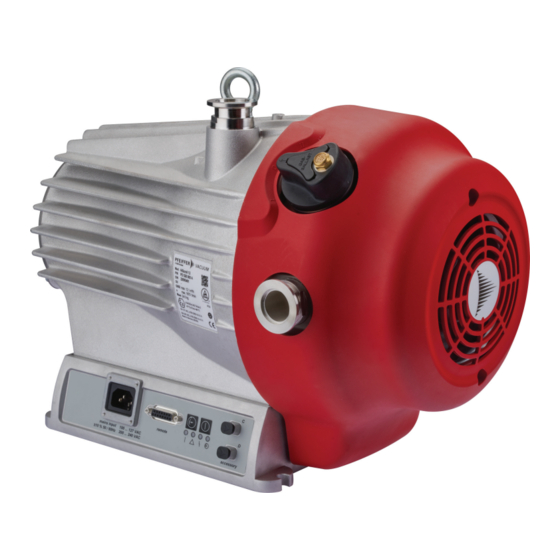
Product description Fig. 3: HiScroll design 1 Protective cover for DN 25 vacuum connection Accessory connection "C" 2 Eye bolt Accessory connection "D" 3 Blank cover for version without GB "Remote" connecting socket 4 Fan cover Electronic drive unit 5 Vacuum connection Base with fixing hole 6 Gas ballast valve for version with GB 7 Version with automated GB (option) -
Page 24: Connections
Interfaces of the electronic drive unit 3.3 Identifying the product ► To ensure clear identification of the product when communicating with Pfeiffer Vacuum, always keep all of the information on the rating plate to hand. ► Learn about certifications through test seals on the product or at www.certipedia.com... -
Page 25: Transportation And Storage
Transportation and Storage 4 Transportation and Storage 4.1 Transporting vacuum pump WARNING Risk of serious injury from swinging, toppling or falling objects During transport, there is a risk of crushing and impact on swinging, toppling or falling objects. There is a risk of injuries to limbs, up to and including bone fractures and head injuries. ►... -
Page 26: Storing The Vacuum Pump
Transportation and Storage Transporting the vacuum pump without its packaging 1 eye bolt is included in the scope of delivery. It is securely bolted to the vacuum pump at the factory. 1. Attach suitable lifting tools to the eye bolt. 2. -
Page 27: Installation
► Do not remove the strainer until you are sure that no solid particles can enter the vacuum pump. Preventing throttling losses Using short vacuum lines with a large nominal diameter prevents throttling losses. Condensate separator Pfeiffer Vacuum recommends the installation of a condensate separator in case vapors are formed from moisture during evacuation. 27/84... -
Page 28: Connecting The Exhaust Side
► Observe the permissible pressures and pressure differentials for the product. ► Check the function of the exhaust line on a regular basis. Condensate separator Pfeiffer Vacuum recommends installing a condensate separator, with condensate drain at the lowest point of the exhaust line. 28/84... -
Page 29: Connecting Gas Ballast External Supply
2. Choose a minimum exhaust line cross section equal to the connection nominal diameter. 3. Install a vacuum connection with small flange components, e.g. fasteners and pipe components DN 25 ISO-KF from the Pfeiffer Vacuum Components Shop. 4. Route the piping downwards from the vacuum pump, to prevent condensate return. -
Page 30: Connecting To Mains Power Supply
Installation The gas ballast system of the scroll pump is suitable for being connected to a gas external supply. Cou- plings for the G 1/8" connection from the Pfeiffer Vacuum accessories range are available for this pur- pose. Required tools ●... -
Page 31: Fig. 9: Connecting To Mains Power Supply
The electronic drive unit starts when the mains supply is established. Establishing mains supply 1. Order a country-specific power cable from the Pfeiffer Vacuum accessories. 2. Always ensure a secure connection to the earthed conductor. 3. Plug the mains cable into the connecting plug of the electronic drive unit. -
Page 32: Interfaces
The 15-pin sub-D connection with the "remote" designation offers the possibility to operate the electron- ic drive unit via remote control. The following specifications are the factory settings for the electronic drive unit. They can be configured with the Pfeiffer Vacuum parameter set. ► Utilize the screened plug and cable. -
Page 33: Inputs
6.2.2 Outputs The digital outputs at the "remote" connection have a maximum load limit of 24 V/50 mA per output. You can configure all listed outputs with the Pfeiffer Vacuum parameter set via the RS-485 interface (description relates to factory settings). -
Page 34: Rs-485
DO2/Pin 9 Active high 6.2.3 RS-485 Connecting RS-485 via D-Sub ► Connect a Pfeiffer Vacuum control unit or an external PC via pin 13 and pin 14 at the D-Sub con- nection of the electronic drive unit. 6.3 Connecting control unit Fig. 12: Connecting a control unit via the "remote"... -
Page 35: Pfeiffer Vacuum Protocol For Rs-485 Interface
3. Connect all devices with RS-485 D+ and RS-485 D- to the bus. 6.5 Pfeiffer Vacuum protocol for RS-485 interface 6.5.1 Telegram frame The telegram frame of the Pfeiffer Vacuum protocol contains only ASCII code characters [32; 127], the exception being the end character of the telegram C . Basically, a master (e.g. -
Page 36: Telegram Description
Interfaces 6.5.2 Telegram description Data query --> Control command --> Data response / Control command understood --> Error message --> NO_DEF Parameter number n2–n0 no longer exists _RANGE Data dn–d0 outside the permissible range _LOGIC Logical access error 6.5.3 Telegram example 1 Data query Current rotation speed (parameter [P:309], device address slave: "123") -->... -
Page 37: Data Types
Interfaces 6.5.5 Data types Data type Description Length Example l1 – l0 boolean_old Logical value (false/true) 000000 is equivalent to false 111111 is equivalent to true u_integer Positive whole number 000000 to 999999 u_real Positive fixed point number 001571 corresponds with 15.71 string Any character string with 6 charac-... -
Page 38: Parameter Set
Important settings and function-related characteristics are factory-programmed into the electronic drive unit as parameters. Each parameter has a three-digit number and a description. The use of the parame- ter is possible via Pfeiffer Vacuum displays and control panels, or externally via RS-485 using Pfeiffer Vacuum protocol. - Page 39 Parameter set Display Designations Functions Data Unit min. max. type cess fault type PressMode Pressure regu- 0 = off lation 1 = on Cfg DO1 Output DO1 0 = Switch-point reached configuration 1 = No error 2 = Error 5 = Set rotation speed reached 6 = Pump on 9 = Always "0"...
-
Page 40: Status Requests
Parameter set 7.3 Status requests Display Designations Func- Data Access Unit min. max. tions type type fault RemotePrio Remote priority 0 = no 1 = yes Error code Error code OvTempElec Excess temperature drive 0 = no electronics 1 = yes OvTempPump Excess temperature pump 0 = no... - Page 41 Parameter set Display Designations Func- Data Access Unit min. max. tions type type fault PrsCorrPi 1 Correction factor 1 RS485Adr RS-485 Interface address Tbl. 12: Reference value inputs 41/84...
-
Page 42: Operation
Important settings and function-related variables are programmed ex factory as parameters in the vac- uum pump electronic drive unit. Each parameter has a three-digit number and a description. Parameter- driven operation and control is supported via Pfeiffer Vacuum displays and control units, or externally via RS-485 using Pfeiffer Vacuum protocol. -
Page 43: Configuring The Digital Outputs
Operation 8.3.1 Configuring the digital outputs Option Description 0 = Rotation speed switchpoint active, once the switch-point is reached reached 1 = No error active, with trouble-free operation 2 = Error active, if the error message is active 5 = Set rotation speed reached active, once the set rotation speed switch-point is reached 6 = Pump on active, if pumping station on, motor on and no error... -
Page 44: Selecting Operating Mode
Operation Fig. 14: Accessory connector assignment 1 + 5 V (blue) + 24 V (depending on software configuration) 2 Sensor RxD / master TxD (white) GND (black) 3 Sensor TxD / master RxD (green) Configuring accessories ► Configure connected accessories with parameters [P:068] and [P:069], if necessary. –... -
Page 45: Normal Operation
3. Check the set rotation speed (parameter [P:308] or [P:397]). 8.5.2 Standby mode Pfeiffer Vacuum recommends standby mode for during process and production stops. When standby mode is active, the electronic drive unit reduces the rotation speed of the vacuum pump. The factory setting is 50 % of the nominal rotation speed. -
Page 46: Auto Boost
Operation Permissible rotation speed range Settings in the rotation speed mode or stand-by mode are subject to the permissible rota- tion speed range of the respective vacuum pump (technical data). The electronic drive unit adjusts the set rotation speed automatically to the next valid value. Set the rotation speed setting mode 1. -
Page 47: Pressure Regulation Operation
Operation 8.6 Pressure regulation operation Option: Pressure sensor ● This function is only available in the version with pressure sensor. ● Pumping explosive atmospheres when using the pressure sensor is not permitted, as the sensor does not have ATEX approval. Pressure regulation operation is only possible with the pressure sensor connected. The pressure sensor measures the intake pressure. -
Page 48: Operating With Gas Ballast
Operation p [hPa] Freon 12 –1 Water vapor –2 –3 –3 –2 –1 [hPa] Fig. 16: Displayed pressure Within the pressure range < 1 hPa, the display is linear. Set calibration factor at electronic drive unit ► Use [P:742] to enter calibration factor and correct displayed measured value. Alternatively: Calculating pressure for gases other than air 1. -
Page 49: Tbl. 17: Hiscroll Gas Ballast Valve Switch Settings
Operation WARNING Risk of poisoning from incorrect use of the gas ballast system The gas ballast system of the scroll pump is vacuum sealed only when used in valid, snapped posi- tions "0", "1" and "2". When operating the valves in intermediate stages, there is a risk that process media can escape to the environment uncontrolled. -
Page 50: Controlling Gas Ballast Valve With A Pressure Sensor
Operation 8.8.1 Controlling gas ballast valve with a pressure sensor Automatic valve control The solenoid valve opens automatically depending on the parametrization and the respec- tive operating status. ● Observe the preset parameters before commissioning. RS-485 RS-485 RS-485 RS-485 Ventilsteuerung [P052] [P030] [P740] [P010]... -
Page 51: Operating Mode Display Via Led
8.9 Operating mode display via LED LEDs on the electronic drive unit show the basic operating states of the vacuum pump. A differentiated error and warning display is only possible for operation with the Pfeiffer Vacuum display and control unit or a PC. - Page 52 Operation Alternative: Switch off via "remote" interface ► Remove the bridge between pins 7 ad 5. 52/84...
-
Page 53: Maintenance
► Disconnect the mains cable from the vacuum pump. NOTICE Danger of property damage from improper maintenance Unprofessional work on the vacuum pump will lead to damage for which Pfeiffer Vacuum accepts no liability. ► We recommend taking advantage of our service training offering. -
Page 54: Checklist For Inspection And Maintenance
We recommend that Pfeiffer Vacuum Service (PV) carry out maintenance work at level 3. Pfeiffer Vacuum will be released from all warranty and liability claims if maintenance work is not carried out properly. This also applies wherever parts other than original spare parts are used. -
Page 55: Removing The Non-Return Valve
Maintenance Required tools ● Face spanner, pin diameter 3 mm, article number: PV D40 012 ● Open-end wrench, WAF 13 ● Calibrated torque wrench (tightening factor ≤ 2.5) 9.3.1 Removing the non-return valve Fig. 19: Removing valve 1 Spiral housing Compression spring 2 O-ring Valve guide 3 Valve plate... -
Page 56: Replacing The Gas Ballast Valve
Maintenance 5. Make sure that the O-ring and valve are seated correctly. 6. Screw the valve into the spiral housing using the face spanner. – Tightening torque: 5 Nm 9.4 Replacing the gas ballast valve Prerequisites ● Vacuum pump switched off ●... -
Page 57: Installing Gas Ballast Valve
Maintenance Fig. 22: Removing gas ballast valve 1 Cylinder screw, 3x Compression spring 2 Gas ballast handle O-ring 3 Valve plate Base plate 4 Weight Removing gas ballast valve 1. Unscrew the cylinder screws from the gas ballast handle. 2. Remove the gas ballast handle from the base plate. 3. -
Page 58: Changing The Tip Seal
Maintenance Fig. 24: Installing gas ballast valve 1 O-ring, 3x Sinter filter 2 Gas ballast valve Ball 3 Special screw Spiral housing 4 Cover Installing gas ballast valve 1. Insert the O-rings into the designated grooves in the spiral housing. 2. -
Page 59: Fig. 25: Loosening The Fan Cover On The Scroll Pump
Maintenance Fig. 25: Loosening the fan cover on the scroll pump 1 Gas ballast valve Hexagon socket screw 2 Fan cover Exhaust connection without protective cap 3 Washer Accessory connection Loosening the fan cover 1. Remove any power supply plugs from the accessory connections (e.g., pressure sensor). 2. -
Page 60: Replacing The Tip Seal
Maintenance Fig. 27: Removing the scroll pump spiral housing 1 Hexagon socket screw (5×) Pump housing 2 Washer (5×) Hexagon socket screw as an auxiliary hole 3 Spiral housing Bottom auxiliary hole 4 Top auxiliary hole Removing the spiral housing 1. -
Page 61: Fig. 28: Replacing The Tip Seal On The Scroll Pump
Maintenance Fig. 28: Replacing the tip seal on the scroll pump 1 Tip seal Tip seal 2 Orbiter O-ring 3 Pump housing Spiral housing Removing the tip seal 1. Place the pump housing in an upright position. 2. Use the o-ring picker and remove the o-ring from the spiral housing. 3. -
Page 62: Assembling The Pump Housing
Maintenance 3. Moisten the groove of the spiral housing with a little isopropanol as an assembly aid for the o-ring. 4. Carefully insert the o-ring into the spiral housing. 9.5.3 Assembling the pump housing Required tools ● Allen key, WAF 5 ●... -
Page 63: Final Inspection
Maintenance 4. Secure the fan housing with both hexagon socket screws and washers. – Tightening torque: 3.5 Nm 5. Optional: Fasten an existing mating plug on the “remote” connection of the electronic drive unit. – Tightening torque: 0.4 Nm 9.6 Final inspection Prerequisite ●... -
Page 64: Decommissioning
1. Clean the vacuum pump exterior with a lint-free cloth and a little isopropanol. 2. If necessary, arrange for Pfeiffer Vacuum Service to completely clean the vacuum pump. 3. Observe the total running time of the vacuum pump and if necessary, use support services of Pfeiffer Vacuum. -
Page 65: Recycling And Disposal
– Fluoroelastomers (FKM) – Potentially contaminated components that come into contact with media 11.2 Disposing of the scroll pump Pfeiffer Vacuum scroll pumps contain materials which must be recycled. 1. Disconnect the electronic drive unit. 2. Dismantle the motor. 3. Decontaminate the components that come into contact with process gases. -
Page 66: Malfunctions
● Incorrect operating volt- ● Supply the correct operating voltage. ● Electronic drive unit de- ● Contact Pfeiffer Vacuum Service. fective The vacuum pump fails to reach ● Leakage on the vacuum 1. Carry out leak detection. -
Page 67: Error Codes
1. Read out error codes via Pfeiffer display and control units or a PC. 2. Remove the cause of the malfunction. 3. Reset the malfunction message with parameter [P:009]. – Use preconfigured quick keys with the symbol or display tiles on Pfeiffer Vacuum display and control units. Error Problem... - Page 68 Malfunctions Error Problem Possible causes Remedy code Err098 Internal communication er- – ● Contact Pfeiffer Vacuum Service Err114 Final stage temperature – ● Contact Pfeiffer Vacuum Service evaluation faulty Err118 Excess temperature, final ● Insufficient ● Check to make sure the fan is working.
-
Page 69: Service Solutions By Pfeiffer Vacuum
We are always focused on perfecting our core competence – servicing of vacuum components. Once you have purchased a product from Pfeiffer Vacuum, our service is far from over. This is often exactly where service begins. Obviously, in proven Pfeiffer Vacuum quality. - Page 70 Service solutions by Pfeiffer Vacuum 5. Prepare the product for transport in accordance with the provisions in the contamination declaration. a) Neutralize the product with nitrogen or dry air. b) Seal all openings with blind flanges, so that they are airtight.
-
Page 71: Spare Parts
Fig. 31: HiScroll maintenance kit 1 1 Tip seal O-ring Spare part package Order number HiScroll 6 HiScroll 12 | HiScroll 18 Maintenance kit 1 – maintenance level 1 PD E10 000 -T PD E20 000 -T Tbl. 24: Spare part package... -
Page 72: Tbl. 25: Spare Part Package
O-ring, 19 × 2.5 2 Compression spring, 2× O-ring, 6 × 3 3 O-ring, 16 × 1.5 Spare part package Order number HiScroll 6 | HiScroll 12 | HiScroll 18 Valve set PD E13 000 -T Tbl. 25: Spare part package 72/84... -
Page 73: Accessories
Accessories 15 Accessories 15.1 Accessory information Display units Display and operating units are used to check and adjust operating parameters. Cable and adapter Mains, interface, connection, and extension cables provide a secure and suitable connection. Different lengths on request Integrated pressure measurement Evaluation and control by the integrated electronic drive unit, independently of an additional power sup- Condensate separator Protect the vacuum pump against fluids from the intake line and from the condensate return from the... -
Page 74: Tbl. 26: Accessories For Hiscroll
Accessories Article Order number Y-connector M12 for RS-485 P 4723 010 USB RS-485 converter PM 061 207 -T Tbl. 26: Accessories for HiScroll 74/84... -
Page 75: Technical Data And Dimensions
Technical data and dimensions 16 Technical data and dimensions 16.1 General Basis for the technical data of Pfeiffer Vacuum spiral vacuum pumps: ● Specifications according to PNEUROP committee PN5 ● ISO 21360-1 2016: “Vacuum technology - Standard methods for measuring vacuum-pump per- formance - Part 1: General description”... - Page 76 Pa m³/s 5 · 10 Pa m³/s Weight 19 kg 19 kg 19 kg Tbl. 29: Technical data for HiScroll 6 Selection field HiScroll 12, scroll HiScroll 12, scroll HiScroll 12, scroll pump, standard, in- pump, without GB, pump, with auto-...
- Page 77 Technical data and dimensions Selection field HiScroll 12, scroll HiScroll 12, scroll HiScroll 12, scroll pump, standard, in- pump, without GB, pump, with auto- cluding ATEX including ATEX mated GB Rated current consump- 100 V – 127 V: 8 A | 100 V –...
-
Page 78: Substances In Contact With The Media
Technical data and dimensions Selection field HiScroll 18, scroll HiScroll 18, scroll HiScroll 18, scroll pump, standard, in- pump, without GB, pump, with auto- cluding ATEX including ATEX mated GB Ambient temperature 5 – 40 °C 5 – 40 °C 5 –... -
Page 79: Dimensions
Technical data and dimensions 16.4 Dimensions 2 0 .5 2 6 0 4× Gummifüße/ rubber feet 1 1 4 DN 25 ISO-KF 2 9 8 2 0 7 .5 2 0 0 3 8 0 220.5 Fig. 33: HiScroll 6 Dimensions in mm 79/84... - Page 80 Technical data and dimensions 30.5 (4x) Gummifüße rubber feet DN 25 ISO-KF Fig. 34: HiScroll 12 | HiScroll 18 Dimensions in mm 80/84...
-
Page 81: Declaration Of Conformity
DIN EN 63000: 2019 Semi S8 0218 EN 61010-1: 2020 The authorized representative for the compilation of technical documents is Dr. Adrian Wirth, Pfeiffer Vacuum GmbH, Berliner Straße 43, 35614 Asslar, Germany. Signature: Pfeiffer Vacuum GmbH Berliner Straße 43 35614 Asslar Germany (Daniel Sälzer) -
Page 82: Declaration Of Conformity
IEC 63000: 2016 Semi S8 0218 IEC 61010-1: 2010 The importer into the United Kingdom and the authorized representative for the compilation of technical documentation is Pfeiffer Vacuum Ltd, 16 Plover Close, Interchange Park, MK169PS Newport Pagnell. Signature: Pfeiffer Vacuum GmbH Berliner Straße 43... - Page 83 83/84...
Need help?
Do you have a question about the HISCROLL 6 and is the answer not in the manual?
Questions and answers