Pfeiffer Vacuum HISCROLL 12 Translation Of The Original
Scroll pump
Hide thumbs
Also See for HISCROLL 12:
- Operating instructions manual (80 pages) ,
- Operating instructions manual (84 pages) ,
- Operating instructions manual (160 pages)

Related Manuals for Pfeiffer Vacuum HISCROLL 12


Summary of Contents for Pfeiffer Vacuum HISCROLL 12
- Page 1 OPERATING INSTRUCTIONS Translation of the Original HISCROLL 12 ∣ 18 Scroll pump...
-
Page 2: Telegram Example
Dear Customer, Thank you for choosing a Pfeiffer Vacuum product. Your new scroll pump is designed to support you with its performance, perfect operation and without impacting your individual application. The name Pfeiffer Vacuum stands for high-quality vacuum technology, a comprehensive and complete range of top-quality products and first-class service. -
Page 3: Table Of Contents
Limits of use of the product Proper use Foreseeable misuse Personnel qualification 2.7.1 Ensuring personnel qualification 2.7.2 Personnel qualification for maintenance and repair 2.7.3 Advanced training with Pfeiffer Vacuum Product description Function 3.1.1 Drive 3.1.2 Cooling 3.1.3 Shaft bearing 3.1.4 Gas ballast 3.1.5 Pressure sensor... - Page 4 Reference value inputs Additional parameter for the DCU Operation Putting the vacuum pump into operation Switching on the vacuum pump Configuring the connections with the Pfeiffer Vacuum parameter set 8.3.1 Configuring the digital outputs 8.3.2 Selecting the interfaces Operating modes Speed modes 8.5.1 Normal operation...
- Page 5 Table of contents 15.4 Dimensions Declaration of conformity 5/66...
- Page 6 Accessories for HiScroll Tbl. 24: Conversion table: Pressure units Tbl. 25: Conversion table: Units for gas throughput Tbl. 26: Technical data for HiScroll 12 Tbl. 27: Technical data for HiScroll 18 Tbl. 28: Materials that make contact with the process media 6/66...
- Page 7 Fig. 17: Removing the scroll pump spiral housing Fig. 18: Replacing the tip seal on the scroll pump Fig. 19: Tip seal nut in the spiral housing Fig. 20: Assembling the housing parts Fig. 21: HiScroll 12 | HiScroll 18 7/66...
-
Page 8: About This Manual
Keep the manual for future consultation. 1.1 Validity This operating instructions is a customer document of Pfeiffer Vacuum. The operating instructions de- scribe the functions of the named product and provide the most important information for the safe use of the device. The description is written in accordance with the valid directives. The information in this op- erating instructions refers to the product's current development status. -
Page 9: Stickers On The Product
Rating plate The rating plate is located clearly visible on a longitudinal side of D-35614 Asslar the vacuum pump. Mod. HiScroll 12 P/N PD S20 000 S/N - - - - - - - - ) max. 12.1 m - - - TÜV Rheinland... -
Page 10: Abbreviations
About this manual Fig. 1: Position of the stickers on the product 1 Rating plate 2 Hot surface warning sign 3 Closure seal 1.3.4 Abbreviations Abbreviation Explanation Operating instructions Display Control Unit Rotation speed value of a vacuum pump (frequency, in rpm or Hz) Fluorinated rubber Handheld Programming Unit [P:xxx]... -
Page 11: Safety
Safety 2 Safety 2.1 General safety information The following 4 risk levels and 1 information level are taken into account in this document. DANGER Immediately pending danger Indicates an immediately pending danger that will result in death or serious injury if not observed. ►... - Page 12 Safety Risks during installation DANGER Danger to life from electric shock Inadequate or incorrect grounding of the unit leads to contact-sensitive voltage on the housing. When making contact, increased leakage currents will cause a life-threatening electric shock. ► Before the installation, check that the connection leads are voltage-free. ►...
- Page 13 Safety CAUTION Danger of injury from bursting as a result of high pressure in the exhaust line Faulty or inadequate exhaust pipes lead to dangerous situations, e.g., increased exhaust pressure. There is a danger of bursting. Injuries caused by flying fragments, the escaping of high pressure, and damage to the unit cannot be excluded.
- Page 14 Safety CAUTION Danger of injury from bursting as a result of high pressure in the exhaust line Faulty or inadequate exhaust pipes lead to dangerous situations, e.g., increased exhaust pressure. There is a danger of bursting. Injuries caused by flying fragments, the escaping of high pressure, and damage to the unit cannot be excluded.
-
Page 15: Safety Precautions
Safety WARNING Crushing and cutting danger on unprotected parts from unforeseeable automatic run-up dur- ing maintenance. During activities on exposed mechanical components, there is a risk of crushing or cut injuries from sudden run-up. ► Switch off the vacuum pump before any maintenance work and work. ►... -
Page 16: Limits Of Use Of The Product
Recommended constant intake pressure 200 hPa Recommended tank size for pumping out ● HiScroll 6: 30 l atmospheric pressure ● HiScroll 12: 60 l ● HiScroll 18: 80 l Installation surface flatness ±10 % Rel. air humidity max. 90 %, non-condensing Ambient temperature 5 ℃... -
Page 17: Personnel Qualification
Such training must ensure that individuals are capable of carrying out the required activi- ties and work steps safely and properly. 2.7.2 Personnel qualification for maintenance and repair Advanced training courses Pfeiffer Vacuum offers advanced training courses to maintenance levels 2 and 3. Adequately trained individuals are: 17/66... -
Page 18: Advanced Training With Pfeiffer Vacuum
─ Customer with Pfeiffer Vacuum service training ─ Pfeiffer Vacuum service technician 2.7.3 Advanced training with Pfeiffer Vacuum For optimal and trouble-free use of this product, Pfeiffer Vacuum offers a comprehensive range of courses and technical trainings. For more information, please contact Pfeiffer Vacuum technical training. -
Page 19: Product Description
3 Product description 3.1 Function The Pfeiffer Vacuum scroll pump is a vacuum pump operating dry in a suction chamber for generating a coarse or medium vacuum according to the physical pumping principle of a spiral vacuum pump. The pump is equipped with an integrated drive and control unit. A three-stage gas ballast system supports the prevention of condensation accumulating in the vacuum pump. -
Page 20: Drive
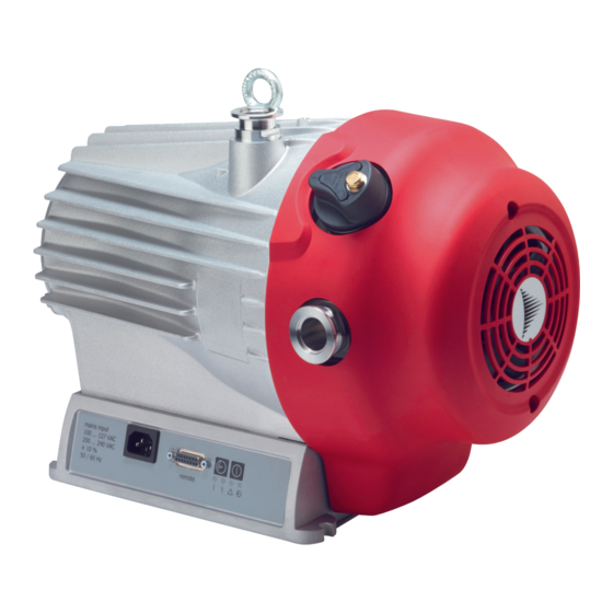
Product description Fig. 3: HiScroll design 1 Protective cover for DN 25 vacuum connection Interfaces of the electronic drive unit 2 Eye bolt Mounting hole 3 Air guide hood Base 4 Vacuum connection 5 Gas ballast valve Protective cover for DN 25 exhaust 6 Exhaust connection Mains supply plug 3.1.1 Drive... -
Page 21: Connections
Interfaces of the electronic drive unit 3.3 Identifying the product ► To ensure clear identification of the product when communicating with Pfeiffer Vacuum, always keep all of the information on the rating plate to hand. ► Learn about certifications through test seals on the product or at www.certipedia.com... -
Page 22: Transportation And Storage
Transportation and Storage 4 Transportation and Storage 4.1 Transporting the vacuum pump WARNING Risk of serious injury from swinging, toppling or falling objects During transport, there is a risk of crushing and impact on swinging, toppling or falling objects. There is a risk of injuries to limbs, up to and including bone fractures and head injuries. ►... -
Page 23: Storing The Vacuum Pump
Transportation and Storage Information for transport of the vacuum pump without packaging 1 eye bolt is included in the scope of delivery. It is securely bolted to the vacuum pump at the factory. 1. Attach suitable lifting tools to the eye bolt. 2. -
Page 24: Installation
5.2 Connecting the vacuum side Preventing throttling losses Using short vacuum connection lines with greater nominal diameter prevents throttling loss- Condensate separator Pfeiffer Vacuum recommends the installation of a condensate separator in case vapors are formed from moisture during evacuation. 24/66... -
Page 25: Connecting The Exhaust Side
► Observe the permissible pressures and pressure differentials for the product. ► Check the function of the exhaust line on a regular basis. Condensate separator Pfeiffer Vacuum recommends installing a condensate separator, with condensate drain at the lowest point of the exhaust line. 25/66... -
Page 26: Connecting The External Gas Ballast Supply
The gas ballast system of the scroll pump is suitable for being connected to an external gas supply. Couplings for the G 1/8" connection from the Pfeiffer Vacuum accessories range are available for this purpose. -
Page 27: Establishing The Mains Connection
Installation Fig. 8: Connecting the gas ballast external supply 1 Sinter filter Gas ballast connection opening 2 Gas ballast valve External gas supply line 3 Example of connecting coupling External gas supply Required tools ● Wrench, WAF 13 ● Calibrated torque wrench (tightening factor ≤ 1.6) Connecting the gas supply 1. -
Page 28: Fig. 9: Establishing Mains Connection
The electronic drive unit starts together with the connection of the voltage supply. Establishing the mains supply 1. Order a corresponding mains connection cable from the Pfeiffer Vacuum accessories range. 2. Always ensure a secure connection to the earthed conductor (PE). -
Page 29: Interfaces
The 15-pin sub-D connection with the "remote" designation offers the possibility to operate the electron- ic drive unit via remote control. The following specifications are the factory settings for the electronic drive unit. You can configure them with the Pfeiffer Vacuum parameter set. ► Use shielded plugs and cables. -
Page 30: Inputs
6.2.2 Outputs The digital outputs at the "remote" connection have a maximum load limit of 24 V/50 mA per output. You can configure all listed outputs with the Pfeiffer Vacuum parameter set via the RS-485 interface (description relates to factory settings). -
Page 31: Rs-485
6.2.3 RS-485 Pin 13 and pin 14 You can connect a Pfeiffer Vacuum display and control unit (DCU or HPU) or an external PC via pin 13 and pin 14 on the D-sub connection of the electronic drive unit. 6.3 Connection options Fig. -
Page 32: Pfeiffer Vacuum Protocol For Rs-485 Interface
3. Connect all devices to the bus with RS-485 D+ and RS-485 D-. 6.5 Pfeiffer Vacuum protocol for RS-485 interface 6.5.1 Telegram frame The telegram frame of the Pfeiffer Vacuum protocol contains only ASCII code characters [32; 127], the exception being the end character of the telegram C. . Basically, a master (e.g. -
Page 33: Telegram Description
Interfaces 6.5.2 Telegram description Data query --> Control command --> Data response / Control command understood --> Error message --> NO_DEF Parameter number n2–n0 no longer exists _RANGE Data dn–d0 outside the permissible range _LOGIC Logical access error 6.5.3 Telegram example 1 Data query Current rotation speed (parameter [P:309], device address slave: "123") -->... -
Page 34: Data Types
Interfaces 6.5.5 Data types Data type Description Length Example l1 – l0 boolean_old Logical value (false/true) 000000 corresponds with false 111111 corresponds with true u_integer Positive whole number 000000 to 999999 u_real Positive fixed point number 001571 corresponds with 15.71 u_expo Positive exponential number 1.2E-2 corresponds with 1,2 ·... -
Page 35: Parameter Set
Important settings and function-related characteristics are factory-programmed into the electronic drive unit as parameters. Each parameter has a three-digit number and a description. The use of the parame- ter is possible via Pfeiffer Vacuum displays and control panels, or externally via RS-485 using Pfeiffer Vacuum protocol. -
Page 36: Status Requests
Parameter set Display Designations Functions Data Unit min. max. type cess fault type PressMode Pressure regu- 0 = off lation 1 = on Cfg DO1 Configuration 0 = Switch-point reached output DO1 1 = No error 2 = Error 5 = Set rotation speed reached 6 = Pump on 9 = Always "0"... -
Page 37: Reference Value Inputs
Parameter set Display Designations Func- Data Access Unit min. max. tions type type fault Nominal Spd Nominal rotation speed (Hz) 999999 DrvPower Drive power 999999 TempPwrStg Final stage temperature °C 999999 TempElec Electronics temperature °C 9999 TempMotor Motor temperature °C 999999 ElecName Electronic drive unit desig-... -
Page 38: Additional Parameter For The Dcu
The basic parameter set is set in the electronic drive unit ex-factory. For controlling con- nected external components (e.g. vacuum measuring instruments), additional parameters (extended parameter set) are available in the corresponding Pfeiffer Vacuum display and control panels. ● Refer to the corresponding operating instructions of the respective components. -
Page 39: Operation
Important settings and function-related variables are programmed ex factory as parameters in the vac- uum pump electronic drive unit. Each parameter has a three-digit number and a description. Parameter- driven operation and control is supported via Pfeiffer Vacuum displays and control units, or externally via RS-485 using Pfeiffer Vacuum protocol. -
Page 40: Selecting The Interfaces
The control is carried out by means of "PLC level". Operation with peripheral devices DCU, HPU or PC 1. When handling the Pfeiffer Vacuum display and control unit, observe the associated operating in- structions: – "DCU" operating instructions available from the Download Center. -
Page 41: Speed Modes
3. Check the set rotation speed (parameter [P:308] or [P:397]). 8.5.2 Standby mode Pfeiffer Vacuum recommends standby mode during process and production stops. When standby mode is active, the electronic drive unit reduces the rotation speed of the vacuum pump. The factory setting is 50 % of the nominal rotation speed. -
Page 42: Speed Actuator Operation
Operation Setting the stand-by rotation speed The vacuum pump has a variable working range from 40 to 100% of the nominal rotation speed. 1. Set the parameter [P:717] to the required value in %. 2. Set the parameter [P:002] to "1". 3. -
Page 43: Pressure Regulation Operation
Operation 8.6 Pressure regulation operation Pressure regulation operation is only possible with the pressure sensor connected. The pressure sensor measures the intake pressure. The electronic drive unit varies the rotation speed of the vacuum pump so that the target pressure is adjusted. If the target pressure cannot be reached under the specified conditions (e.g. -
Page 44: Operating Mode Display Via Led
8.8 Operating mode display via LED LEDs on the electronic drive unit show the basic operating states of the vacuum pump. A differentiated error and warning display is only possible for operation with the Pfeiffer Vacuum display and control unit or a PC. -
Page 45: Switching Off The Vacuum Pump
1. Switch the running vacuum pump off by pressing the button once. 2. Switch the voltage supply off. Alternative: Switching off via the Pfeiffer Vacuum parameter ► Set the parameter [P:010] to the value "0". Alternative: Switching off via "remote” interface ►... -
Page 46: Maintenance
► Disconnect the mains cable from the vacuum pump. NOTICE Danger of property damage from improper maintenance Unprofessional work on the vacuum pump will lead to damage for which Pfeiffer Vacuum accepts no liability. ► We recommend taking advantage of our service training offering. -
Page 47: Changing The Tip Seal
We recommend that Pfeiffer Vacuum Service (PV) carry out maintenance work at level 3. Pfeiffer Vacuum will be released from all warranty and liability claims if maintenance work is not carried out properly. This also applies wherever parts other than original spare parts are used. -
Page 48: Fig. 15: Loosening The Fan Cover On The Scroll Pump
Maintenance Fig. 15: Loosening the fan cover on the scroll pump 1 Gas ballast valve Interior hexagon socket screw 2 Fan cover Exhaust connection without protective cap 3 Washer Remote plug (optional) Loosening the fan cover 1. Undo an existing mating plug (e.g. for accessories) on the “remote” connection of the electronic drive unit. -
Page 49: Replacing The Tip Seal
Maintenance Fig. 17: Removing the scroll pump spiral housing 1 Interior hexagon socket screw (5×) Pump housing 2 Washer (5×) Interior hexagon socket screw as an auxiliary hole 3 Spiral housing Bottom auxiliary hole 4 Top auxiliary hole Removing the spiral housing 1. -
Page 50: Fig. 18: Replacing The Tip Seal On The Scroll Pump
Maintenance Fig. 18: Replacing the tip seal on the scroll pump 1 Tip seal Tip seal 2 Orbiter O-ring 3 Pump housing Spiral housing Removing the tip seal 1. Place the pump housing in an upright position. 2. Use the o-ring picker and remove the o-ring from the spiral housing. 3. -
Page 51: Assembling The Pump Housing
Maintenance 3. Moisten the groove of the spiral housing with a little isopropanol as an assembly aid for the o-ring. 4. Carefully insert the o-ring into the spiral housing. 9.3.3 Assembling the pump housing Required tool ● Allen key, WAF 5 ●... - Page 52 Maintenance 4. Secure the fan housing with both interior hexagon socket screws and washers. – Tightening torque: 3.5 Nm 5. Optional: Fasten an existing mating plug on the “remote” connection of the electronic drive unit. – Tightening torque: 0.4 Nm 52/66...
-
Page 53: Decommissioning
1. Clean the vacuum pump exterior with a lint-free cloth and a little isopropanol. 2. If necessary, arrange for Pfeiffer Vacuum Service to completely clean the vacuum pump. 3. Observe the total running time of the vacuum pump and if necessary, use support services of Pfeiffer Vacuum. -
Page 54: Recycling And Disposal
– Fluoroelastomers (FKM) – Potentially contaminated components that come into contact with media 11.2 Disposing of the scroll pump Pfeiffer Vacuum scroll pumps contain materials which must be recycled. 1. Disconnect the electronic drive unit. 2. Dismantle the motor. 3. Decontaminate the components that come into contact with process gases. -
Page 55: Malfunctions
● Incorrect operating volt- ● Supply the correct operating voltage. ● Electronic drive unit de- ● Contact Pfeiffer Vacuum Service. fective The vacuum pump fails to reach ● Leakage on the vac- 1. Carry out leak detection. -
Page 56: Error Codes
Malfunctions Unusual noises during operation ● Bearing is damaged ● Contact Pfeiffer Vacuum Service. ● Rotor damaged ● Contact Pfeiffer Vacuum Service. ● Spiral element contami- ● Contact Pfeiffer Vacuum Service. nated or damaged Red LED on the electronic drive ●... -
Page 57: Warning And Error Messages When Operating With Dcu
Malfunctions Error Problem Possible causes Remedy code Err825 Internal communication error ● Contact Pfeiffer Vacuum Service Err913 Direction of rotation Incorrect direction of ● Contact Pfeiffer Vacuum Service rotation Tbl. 20: Error messages of the electronic drive unit Error code... -
Page 58: Service Solutions By Pfeiffer Vacuum
We are always focused on perfecting our core competence – servicing of vacuum components. Once you have purchased a product from Pfeiffer Vacuum, our service is far from over. This is often exactly where service begins. Obviously, in proven Pfeiffer Vacuum quality. - Page 59 Service solutions by Pfeiffer Vacuum 5. Prepare the product for transport in accordance with the provisions in the contamination declaration. a) Neutralize the product with nitrogen or dry air. b) Seal all openings with blind flanges, so that they are airtight.
-
Page 60: Accessories
Accessories 14 Accessories 14.1 Accessory information Display units Display and operating units are used to check and adjust operating parameters. Cable and adapter Mains, interface, connection, and extension cables provide a secure and suitable connection. Different lengths on request Integrated pressure measurement Evaluation and control by the integrated electronic drive unit, independently of an additional power sup- Condensate separator Protect the vacuum pump against fluids from the intake line and from the condensate return from the... -
Page 61: Technical Data And Dimensions
Technical data and dimensions 15 Technical data and dimensions 15.1 General Basis for the technical data of Pfeiffer Vacuum spiral vacuum pumps: ● Specifications according to PNEUROP committee PN5 ● ISO 21360-1 2016: “Vacuum technology - Standard methods for measuring vacuum-pump per- formance - Part 1: General description”... -
Page 62: Tbl. 26: Technical Data For Hiscroll
5 · 10 Pa m³/s 5 · 10 Pa m³/s Weight 24 kg 24 kg Tbl. 26: Technical data for HiScroll 12 Selection field HiScroll 18, Scroll Pump, HiScroll 18, Scroll Pump, Standard Standard, incl. pressure sensor Connection flange (in) -
Page 63: Substances In Contact With The Media
Technical data and dimensions Selection field HiScroll 18, Scroll Pump, HiScroll 18, Scroll Pump, Standard Standard, incl. pressure sensor Protection degree IP20 IP20 Ambient temperature 5 – 40 °C 5 – 40 °C Temperature: Storage -10 – 50 °C -10 – 50 °C Temperature: Shipping -25 –... -
Page 64: Fig. 21: Hiscroll 12 | Hiscroll
Technical data and dimensions DN 25 ISO-KF DN 25 ISO-KF Fig. 21: HiScroll 12 | HiScroll 18 64/66... - Page 65 ISO 21360-1: 2016 DIN EN 50581: 2013 ISO 21360-2: 2012 The authorized representative for the compilation of technical documents is Mr. Wolf- gang Bremer, Pfeiffer Vacuum GmbH, Berliner Straße 43, 35614 Asslar, Germany. Signature: Pfeiffer Vacuum GmbH Berliner Straße 43...
Need help?
Do you have a question about the HISCROLL 12 and is the answer not in the manual?
Questions and answers