Pfeiffer Vacuum HISCROLL 18 Operating Instructions Manual
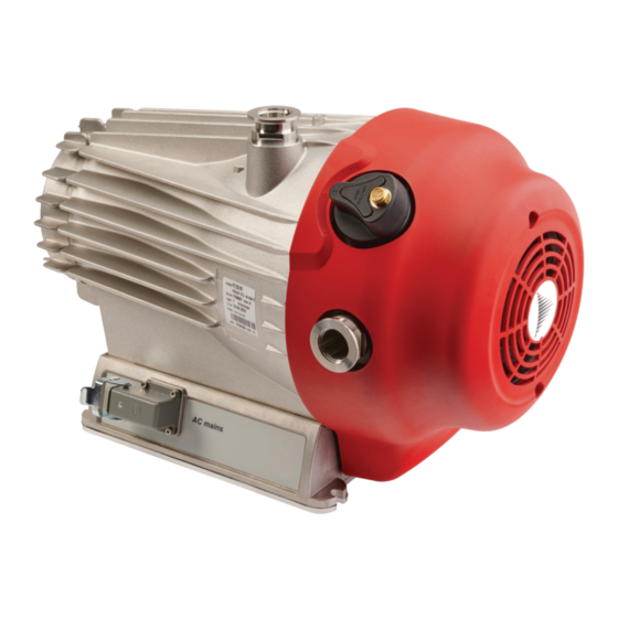
Scroll pump with three-phase motor
Hide thumbs
Also See for HISCROLL 18:
- Operating instructions manual (160 pages) ,
- Translation of the original (66 pages) ,
- Operating instructions manual (80 pages)

Related Manuals for Pfeiffer Vacuum HISCROLL 18


Summary of Contents for Pfeiffer Vacuum HISCROLL 18
- Page 1 OPERATING INSTRUCTIONS Translation of the Original HISCROLL 18 Scroll pump with three-phase motor...
- Page 2 Dear Customer, Thank you for choosing a Pfeiffer Vacuum product. Your new scroll pump is designed to support you with its performance, perfect operation and without impacting your individual application. The name Pfeiffer Vacuum stands for high-quality vacuum technology, a comprehensive and complete range of top-quality products and first-class service.
-
Page 3: Table Of Contents
Limits of use of product Proper use Foreseeable improper use Personnel qualification 2.8.1 Ensuring personnel qualification 2.8.2 Personnel qualification for maintenance and repair 2.8.3 Advanced training with Pfeiffer Vacuum Product description Function 3.1.1 Drive 3.1.2 Cooling 3.1.3 Shaft bearing 3.1.4 Gas ballast... - Page 4 Shutting down for longer periods Recommissioning Recycling and disposal General disposal information Disposing of the scroll pump Malfunctions 10.1 General Service solutions by Pfeiffer Vacuum Spare parts Accessories 13.1 Accessory information 13.2 Ordering accessories Technical data and dimensions 14.1 General 14.2 Technical data...
- Page 5 Spare part package Tbl. 16: Accessories for HiScroll Tbl. 17: Conversion table: Pressure units Tbl. 18: Conversion table: Units for gas throughput Tbl. 19: Technical data for HiScroll 18 | 3-phase Tbl. 20: Materials that make contact with the process media 5/64...
- Page 6 Replacing the tip seal on the scroll pump Fig. 23: Tip seal nut in the spiral housing Fig. 24: Assembling the housing parts Fig. 25: HiScroll maintenance kit 1 Fig. 26: HiScroll valve set Fig. 27: HiScroll 18 | 3-phase 6/64...
-
Page 7: About This Manual
Keep the manual for future consultation. 1.1 Validity These operating instructions are a customer document of Pfeiffer Vacuum. The operating instructions describe the functions of the named product and provide the most important information for the safe use of the device. The description is written in accordance with the valid directives. The information in these operating instructions refers to the product's current development status. -
Page 8: Stickers On Product
3..1.3.3 Stickers on product This section describes all the stickers on the product along with their meanings. Rating plate HiScroll 18 (example) The rating plate is located clearly visible on a longitudinal side of D-35614 Asslar Berliner Str. 43 the vacuum pump. -
Page 9: Abbreviations
About this manual Fig. 1: Position of the stickers on the product 1 Note: Read the operating instructions 2 Rating plate 3 Hot surface warning sign 1.3.4 Abbreviations Abbreviation Explanation ATEX ATmosphères EXplosibles Atmospheric pressure Operating instructions Rotation speed value of a vacuum pump (frequency, in rpm or Hz) Fluorinated rubber Gas ballast High vacuum... -
Page 10: Safety
Safety 2 Safety 2.1 General safety information The following 4 risk levels and 1 information level are taken into account in this document. DANGER Immediately pending danger Indicates an immediately pending danger that will result in death or serious injury if not observed. ►... - Page 11 Safety Risks during installation DANGER Danger to life from electric shock Touching exposed and voltage-bearing elements causes an electric shock. Improper connection of the mains supply leads to the risk of touchable live housing parts. There is a risk to life. ►...
- Page 12 Safety WARNING Mortal danger from electric shock caused by water damage The device is not protected against water ingress. Vacuum pumps operated on the floor lead to leak- age current in penetrating and surrounding water. There is a danger to life from electric shock when making contact with live water.
- Page 13 Safety WARNING Danger of poisoning due to toxic process media escaping from the exhaust pipe During operation with no exhaust line, the vacuum pump allows exhaust gases and vapors to escape freely into the air. There is a risk of injury and fatality due to poisoning in processes with toxic process media.
- Page 14 ► Install suitable touch protection if the vacuum pump is accessible to untrained persons. ► Allow the vacuum pump to cool down before carrying out any work. ► Contact Pfeiffer Vacuum for suitable touch protection in system solutions. CAUTION Danger of injury if hair or loose clothing is pulled in There is a danger of injury from getting pulled in at rotating parts of the fan.
-
Page 15: Safety Precautions
Safety WARNING Health hazard through poisoning from toxic contaminated components or devices Toxic process media result in contamination of devices or parts of them. During maintenance work, there is a risk to health from contact with these poisonous substances. Illegal disposal of toxic sub- stances causes environmental damage. -
Page 16: Atex Classification And Safety Measures
Safety ► Always ensure a secure connection to the earthed conductor (PE). ► Never disconnect plug connections during operation. ► Observe the above shutdown procedures. ► Before working on the vacuum pump, wait until complete standstill (rotation speed f = 0). ►... -
Page 17: Limits Of Use Of Product
Safety Classification Description Temperature Classification of equipment depending on their maximum surface temperature, in class accordance with assignment as follows: Temperature class --> Maximum surface temperature/gas temperature: ● T1 --> +450 °C ● T2 --> +300 °C ● T3 --> +200 °C ●... -
Page 18: Proper Use
The work described in this document may only be carried out by persons who have appropriate profes- sional qualifications and the necessary experience or who have completed the necessary training as provided by Pfeiffer Vacuum. Training people 1. Train the technical personnel on the product. -
Page 19: Personnel Qualification For Maintenance And Repair
─ Customer with Pfeiffer Vacuum service training ─ Pfeiffer Vacuum service technician 2.8.3 Advanced training with Pfeiffer Vacuum For optimal and trouble-free use of this product, Pfeiffer Vacuum offers a comprehensive range of courses and technical trainings. For more information, please contact Pfeiffer Vacuum technical training. -
Page 20: Product Description
3 Product description 3.1 Function The Pfeiffer Vacuum scroll pump is a vacuum pump operating dry in a suction chamber for generating a coarse or medium vacuum according to the physical pumping principle of a spiral vacuum pump. A three-stage gas ballast system supports the prevention of condensation accumulating in the vacuum pump. -
Page 21: Drive
3.2 Identifying the product ► To ensure clear identification of the product when communicating with Pfeiffer Vacuum, always keep all of the information on the rating plate to hand. ► Learn about certifications through test seals on the product or at www.certipedia.com... -
Page 22: Scope Of Delivery
Product description 3.4 Scope of delivery ● Scroll pump ● Protective cap for vacuum connection ● Protective cap for the exhaust connection ● Operating instructions 22/64... -
Page 23: Transportation And Storage
Transportation and Storage 4 Transportation and Storage 4.1 Transporting vacuum pump WARNING Risk of serious injury from swinging, toppling or falling objects During transport, there is a risk of crushing and impact on swinging, toppling or falling objects. There is a risk of injuries to limbs, up to and including bone fractures and head injuries. ►... -
Page 24: Storing The Vacuum Pump
Transportation and Storage Transporting vacuum pump without packaging 1 eye bolt is included in the scope of delivery. It is securely bolted to the vacuum pump at the factory. 1. Attach suitable lifting tools to the eye bolt. 2. Pay attention to the correct use and fastening of the lifting equipment. 3. -
Page 25: Installation
► Do not remove the strainer until you are sure that no solid particles can enter the vacuum pump. Preventing throttling losses Using short vacuum lines with a large nominal diameter prevents throttling losses. Condensate separator Pfeiffer Vacuum recommends the installation of a condensate separator in case vapors are formed from moisture during evacuation. 25/64... -
Page 26: Connecting Exhaust Side
► Observe the permissible pressures and pressure differentials for the product. ► Check the function of the exhaust line on a regular basis. Condensate separator Pfeiffer Vacuum recommends installing a condensate separator, with condensate drain at the lowest point of the exhaust line. 26/64... -
Page 27: Connecting Gas Ballast External Supply
2. Choose a minimum exhaust line cross section equal to the connection nominal diameter. 3. Install a vacuum connection with small flange components, e.g. fasteners and pipe components DN 25 ISO-KF from the Pfeiffer Vacuum Components Shop. 4. Route the piping downwards from the vacuum pump, to prevent condensate return. -
Page 28: Implementing Electrical Safety Measures
Installation The gas ballast system of the scroll pump is suitable for being connected to a gas external supply. Cou- plings for the G 1/8" connection from the Pfeiffer Vacuum accessories range are available for this pur- pose. Required tools ●... -
Page 29: Installing Miniature Circuit Breaker
Installation 5.5.1 Installing miniature circuit breaker Circuit breaker (MCB) Tripping characteristic B or C according to IEC 60947-2 Interruption rating (AIC) 10 kA Rated current I 2.5 A for voltage 380 – 415 V, 50 Hz Tbl. 6: Technical requirements for a miniature circuit breaker Procedure ►... -
Page 30: Connecting Three-Phase Motor With 6-Pin Terminal Board
Installation WARNING Risk of injury due to incorrect installation Dangerous situations may arise from unsafe or incorrect installation. ► Do not carry out your own conversions or modifications on the unit. ► Ensure the integration into an Emergency Off safety circuit. WARNING Mortal danger from electric shock caused by water damage The device is not protected against water ingress. -
Page 31: Choosing Fan Voltage Supply
Installation There are 2 different circuit configurations: ● Star circuit for high voltage ● Delta connection for low voltage Fig. 9: Star circuit for high voltage (factory setting) The ends of the 3 phases are connected in the star point. The mains voltage is √3 times the phase volt- age. -
Page 32: Checking Direction Of Rotation With Rotary Field Measuring Instrument
Installation FAN _2 FAN _1 Fig. 11: Clamping fan connecting cable onto circuit board 1 Circuit board Fan connecting cable from terminal block 2 Spring clamp for motor in star circuit Spring clamp for motor in delta connection Connecting fan 1. - Page 33 Installation 3. Switch on the scroll pump briefly (2 to 3 seconds). – The protective cap on the vacuum connection is sucked in and bulges downwards. 4. If the protective cap is pushed upwards or raised, replace the 2 phases on the connecting cable. 33/64...
-
Page 34: Operation
Operation 6 Operation 6.1 Commissioning vacuum pump WARNING Risk of explosion in the medium to be pumped as a result of increased pressure With installation on the exhaust side, there is a risk of the exhaust pressure of the vacuum pump ex- ceeding the atmospheric conditions. -
Page 35: Temperature Monitoring
► Install suitable touch protection if the vacuum pump is accessible to untrained persons. ► Allow the vacuum pump to cool down before carrying out any work. ► Contact Pfeiffer Vacuum for suitable touch protection in system solutions. Operating conditions ●... -
Page 36: Tbl. 11: Hiscroll Gas Ballast Valve Switch Settings
Operation WARNING Risk of poisoning from incorrect use of the gas ballast system The gas ballast system of the scroll pump is vacuum sealed only when used in valid, snapped posi- tions "0", "1" and "2". When operating the valves in intermediate stages, there is a risk that process media can escape to the environment uncontrolled. -
Page 37: Switching Off Vacuum Pump
Operation 6.5 Switching off vacuum pump Procedure 1. If required, switch the vacuum pump off in each pressure range. 2. Safely disconnect the drive motor from the mains. – The vacuum safety valve closes automatically when the vacuum pump is switched off, pre- venting the backflow of gas into the intake line. -
Page 38: Maintenance
► Disconnect the mains cable from the vacuum pump. NOTICE Danger of property damage from improper maintenance Unprofessional work on the vacuum pump will lead to damage for which Pfeiffer Vacuum accepts no liability. ► We recommend taking advantage of our service training offering. -
Page 39: Checklist For Inspection And Maintenance
We recommend that Pfeiffer Vacuum Service (PV) carry out maintenance work at level 3. Pfeiffer Vacuum will be released from all warranty and liability claims if maintenance work is not carried out properly. This also applies wherever parts other than original spare parts are used. -
Page 40: Removing Non-Return Valve
Maintenance 7.3.1 Removing non-return valve Fig. 13: Removing valve 1 Spiral housing Compression spring 2 O-ring Valve guide 3 Valve plate Removing valve 1. Use the face spanner to unscrew the valve guide with compression spring and valve plate from the spiral housing. 2. -
Page 41: Replacing The Gas Ballast Valve
Maintenance 7.4 Replacing the gas ballast valve Prerequisites ● Vacuum pump switched off ● Vacuum system vented to atmospheric pressure ● Electrical supply disconnected ● Mains cable disconnected ● Vacuum inlet sealed with the original protective cover Required tools ● Slot screwdriver ●... -
Page 42: Installing Gas Ballast Valve
Maintenance Fig. 16: Removing gas ballast valve 1 Cylinder screw, 3x Compression spring 2 Gas ballast handle O-ring 3 Valve plate Base plate 4 Weight Removing gas ballast valve 1. Unscrew the cylinder screws from the gas ballast handle. 2. Remove the gas ballast handle from the base plate. 3. -
Page 43: Changing The Tip Seal
Maintenance Fig. 18: Installing gas ballast valve 1 O-ring, 3x Sinter filter 2 Gas ballast valve Ball 3 Special screw Spiral housing 4 Cover Installing gas ballast valve 1. Insert the o-rings into the designated grooves in the spiral housing. 2. -
Page 44: Fig. 19: Loosening The Fan Cover On The Scroll Pump
Maintenance Fig. 19: Loosening the fan cover on the scroll pump 1 Gas ballast valve Hexagon socket screw 2 Fan cover Exhaust connection without protective cap 3 Washer Loosening the fan cover 1. Unscrew the 2 hexagon socket screws with washers from the fan cover. 2. -
Page 45: Replacing The Tip Seal
Maintenance Fig. 21: Removing the scroll pump spiral housing 1 Hexagon socket screw (5×) Pump housing 2 Washer (5×) Hexagon socket screw as an auxiliary hole 3 Spiral housing Bottom auxiliary hole 4 Top auxiliary hole Removing the spiral housing 1. -
Page 46: Fig. 22: Replacing The Tip Seal On The Scroll Pump
Maintenance Fig. 22: Replacing the tip seal on the scroll pump 1 Tip seal Tip seal 2 Orbiter O-ring 3 Pump housing Spiral housing Removing the tip seal 1. Place the pump housing in an upright position. 2. Use the o-ring picker and remove the o-ring from the spiral housing. 3. -
Page 47: Assembling Pump Housing
Maintenance 3. Moisten the groove of the spiral housing with a little isopropanol as an assembly aid for the o-ring. 4. Carefully insert the o-ring into the spiral housing. 7.5.3 Assembling pump housing Required tools ● Allen key, WAF 5 ● Calibrated torque wrench Required consumables ●... -
Page 48: Final Inspection
Maintenance 7.6 Final inspection Prerequisite ● Maintenance work carried out on opening the housing ● Fan disassembled or replaced Carrying out final inspection ► Perform a functional test. ► Check to make sure the fan is working. ► Carry out a high voltage and protective earthing test. Recommended final check ►... -
Page 49: Decommissioning
1. Clean the vacuum pump exterior with a lint-free cloth and a little isopropanol. 2. If necessary, arrange for Pfeiffer Vacuum Service to completely clean the vacuum pump. 3. Observe the total running time of the vacuum pump and if necessary, use support services of Pfeiffer Vacuum. -
Page 50: Recycling And Disposal
– Fluoroelastomers (FKM) – Potentially contaminated components that come into contact with media 9.2 Disposing of the scroll pump Pfeiffer Vacuum scroll pumps contain materials which must be recycled. 1. Disconnect the electronic drive unit. 2. Dismantle the motor. 3. Decontaminate the components that come into contact with process gases. -
Page 51: Malfunctions
● Fuse on site defective ● Check the fuse. ● Motor protection switch defec- ● Check the motor protection switch. tive ● Contact Pfeiffer Vacuum Service. ● Vacuum pump blocked ● Contact Pfeiffer Vacuum Service. ● Motor faulty ● Temperature threshold value of ●... - Page 52 ● When the reset temperature is reached, switch the vacuum pump back on manually via the mo- tor protection switch. Unusual noises during op- ● Bearing is damaged ● Contact Pfeiffer Vacuum Service. eration ● Rotor damaged ● Contact Pfeiffer Vacuum Service. ● Spiral element contaminated or ●...
-
Page 53: Service Solutions By Pfeiffer Vacuum
We are always focused on perfecting our core competence – servicing of vacuum components. Once you have purchased a product from Pfeiffer Vacuum, our service is far from over. This is often exactly where service begins. Obviously, in proven Pfeiffer Vacuum quality. - Page 54 Service solutions by Pfeiffer Vacuum 5. Prepare the product for transport in accordance with the provisions in the contamination declaration. a) Neutralize the product with nitrogen or dry air. b) Seal all openings with blind flanges, so that they are airtight.
-
Page 55: Spare Parts
► Install original spare parts only. Fig. 25: HiScroll maintenance kit 1 1 Tip seal O-ring Spare part package HiScroll type Order number Maintenance kit 1 – maintenance level 1 HiScroll 18 PD E20 000 -T Tbl. 14: Spare part package 55/64... -
Page 56: Tbl. 15: Spare Part Package
1 Valve plate, 2× O-ring, 19 × 2.5 2 Compression spring, 2× O-ring, 6 × 3 3 O-ring, 16 × 1.5 Spare part package HiScroll type Order number Valve set HiScroll 18 PD E13 000 -T Tbl. 15: Spare part package 56/64... -
Page 57: Accessories
Accessories 13 Accessories 13.1 Accessory information Cable and adapter Mains, interface, connection, and extension cables provide a secure and suitable connection. Different lengths on request Condensate separator Protect the vacuum pump against fluids from the intake line and from the condensate return from the exhaust line Dust separator Protect the vacuum pump from particles from the process... -
Page 58: Technical Data And Dimensions
Technical data and dimensions 14 Technical data and dimensions 14.1 General Basis for the technical data of Pfeiffer Vacuum spiral vacuum pumps: ● Specifications according to PNEUROP committee PN5 ● ISO 21360-1 2016: “Vacuum technology - Standard methods for measuring vacuum-pump per- formance - Part 1: General description”... -
Page 59: Substances In Contact With The Media
Technical data and dimensions Selection field HiScroll 18, Scroll pump, three-phase motor, in- cluding ATEX Rotation speed at 50 Hz 1460 rpm Rotation speed at 60 Hz 1760 rpm Input voltage 50 Hz 190 – 220 / 380 – 415 V Input voltage 60 Hz 200 –... -
Page 60: Dimensions
Technical data and dimensions 14.4 Dimensions 64.5 (4x) Gummifüße rubber feet 255.5 Fig. 27: HiScroll 18 | 3-phase 60/64... -
Page 61: Ec Declaration Of Conformity
DIN EN ISO 80079-36: 2016–12 ISO 21360-2: 2020 DIN EN ISO 80079-37: 2016–12 The authorized representative for the compilation of technical documents is Dr. Adrian Wirth, Pfeiffer Vacuum GmbH, Berliner Straße 43, 35614 Asslar, Germany. Signature: Pfeiffer Vacuum GmbH Berliner Straße 43... -
Page 62: Declaration Of Conformity
ISO 21360-2: 2020 EN ISO 80079-37: 2016 The manufacturer's authorized representative in the United Kingdom and the authorized agent for compiling the technical documentation is Pfeiffer Vacuum Ltd, 16 Plover Close, In- terchange Park, MK169PS Newport Pagnell. Signature: Pfeiffer Vacuum GmbH Berliner Straße 43... - Page 63 63/64...
Need help?
Do you have a question about the HISCROLL 18 and is the answer not in the manual?
Questions and answers