Table of Contents
Advertisement
Quick Links
Advertisement
Table of Contents

Subscribe to Our Youtube Channel
Related Manuals for Pfeiffer Vacuum UNO 35


Summary of Contents for Pfeiffer Vacuum UNO 35
- Page 1 OPERATING INSTRUCTIONS Original UNO 35/65 | DUO 35/65 Rotary Vane Pump...
- Page 2 PK0168BEN_Q PK0168 2018-01-31...
-
Page 3: Table Of Contents
Table of contents Table of contents About this manual Validity 1.1.1 Related documents 1.1.2 Variants Target group Conventions 1.3.1 Abbreviations 1.3.2 Pictographs 1.3.3 Stickers in the product 1.3.4 Symbols used 1.3.5 Instructions in the text Safety General safety instructions Safety instructions Safety precautions Safety precautions for handling pumps with magnetic coupling Limits of use of the product... - Page 4 Checking the oil level in the oiler (C version pumps only) Decommissioning Shutting down for longer periods Recommissioning Disposal Malfunctions Service solutions from Pfeiffer Vacuum Spare parts 11.1 Spare parts packs 11.1.1Set of seals 11.1.2Maintenance kit 1 – maintenance level 1 11.1.3Overhaul kit and set of seals 11.1.4Set of vanes...
-
Page 5: About This Manual
Keep the manual for future consultation. 1.1 Validity These operating instructions are for customers of Pfeiffer Vacuum. They describe the function of the designated product and provide the most important information for a safe usage of the product. The de- scriptions comply with applicable directives. All information provided in these operating instructions refer to the current development status of the product. -
Page 6: Conventions
About this manual The work described in this document is only permitted to be performed by persons with the appropriate technical qualifications (expert personnel) or who have received the relevant training from Pfeiffer Vac- uum. 1.3 Conventions 1.3.1 Abbreviations Abbreviation Meaning in this document C version Corrosive gas version M version... -
Page 7: Symbols Used
About this manual 1.3.4 Symbols used Vacuum connection Exhaust connection Gas ballast connection Measurement connection Electrical connection Tbl. 3: Symbols used in this document 1.3.5 Instructions in the text Usage instructions in the document follow a general structure that is complete in itself. The required ac- tion is indicated by a individual or multi-part action steps. -
Page 8: Safety
Safety 2 Safety 2.1 General safety instructions This document includes the following four risk levels and one information level. DANGER Imminent danger Indicates a hazardous situation which, if not avoided, will result in death or serious injury. ► Instructions on avoiding the hazardous situation WARNING Possibly imminent danger Indicates a hazardous situation which, if not avoided, could result in death or serious injury. - Page 9 Safety Risks during installation WARNING Danger of injury from electric shock Contact with live parts causes electric shock. ► Make sure that connection leads are voltage-free. ► Make sure that electrical installations are only carried out by qualified electricians. ► Provide adequate grounding for the device. WARNING Danger of poisoning from toxic vapors Igniting and heating synthetic operating fluid generates toxic vapors.
-
Page 10: Safety Precautions
Safety WARNING Danger to life from electric shock in the event of a fault In the event of a fault, parts connected to the mains may be live. ► Always keep the mains connection freely accessible so you can disconnect it at any time. WARNING Health risk and environmental damage due to poisoning on toxic contaminated parts or devi- Toxic process media result in contamination of the devices or parts thereof. -
Page 11: Limits Of Use Of The Product
Pfeiffer Vacuum. ► Adhere to the installation, commissioning, operating, and maintenance instructions. ► Do not use any accessory parts other than those recommended by Pfeiffer Vacuum. 2.7 Foreseeable improper use Improper use of the product invalidates all warranty and liability claims. Improper use is any, even unin- tended, use, which is contrary to the product purpose;... -
Page 12: Product Description
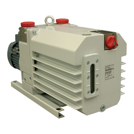
Product description 3 Product description 3.1 Product identification To ensure reliable identification of the product when communicating with Pfeiffer Vacuum, always keep all of the information on the rating plate to hand. D-35641 Asslar Mod.: DUO 65 Mod.-Nr.: PK D46 xxx Ser.- Nr.: 3454440 max. - Page 13 Product description Fig. 2: Design of Uno 35/65 | Duo 35/65 Vacuum flange Drain screw for operating fluid Exhaust flange Sight glass Filling screw for operating fluid Locking screw for flushing gas pipe Base plate Gas ballast valve Support stand Fig.
-
Page 14: Operating Principle
Product description 3.4 Operating principle Fig. 4: UnoLine and DuoLine operating principle Housing Suction chamber Rotor Exhaust (outlet) Vane Vacuum flange (inlet) The rotary vane pump is an oil-sealed rotary displacement pump. The pumping system is made up of the housing, the eccentrically mounted rotor, and the centrifugally- and spring-loaded radially sliding vanes, which divide the suction chamber into multiple chambers. -
Page 15: Transportation And Storage
2. Lift the pump out of the transport packaging. 3. To lift the pump, use the crane lug provided for this purpose, located on the top of the pump. 4.2 Storage Pfeiffer Vacuum recommends storing the products in their original transport pack- aging. Storing the pump 1. - Page 16 Transportation and Storage 4. Store the pump only in dry, dust-free rooms, within the specified ambient conditions: 5. In rooms with humid or aggressive atmospheres: Hermetically shrink-wrap the pump together with a drying agent in a plastic bag. 6. Change the operating fluid if the storage period is longer than 2 years. 16/66...
-
Page 17: Installation
Installation 5 Installation 5.1 Installing the pump ● Indoors, protected from dust deposits Installation location ● Outdoors, protected from direct weather influences Installation altitude max. 2000 m Orientation as level as possible; max. permissible angle of inclination: ±10° Ambient temperature +12°C to +40°C Relative air humidity max. -
Page 18: Connecting The Vacuum Side
Installation 5.2 Connecting the vacuum side Fig. 7: Connecting the vacuum side Protective cap Intake line O-ring Circlip Establishing the vacuum connection 1. Make sure that the cone stainer and centering ring are in the intake duct. 2. Remove the protective cap from the vacuum flange. 3. - Page 19 Installation CAUTION Danger of injury from bursting as a result of high pressure in the exhaust line Faulty or short exhaust lines cause hazardous situations, e.g. exhaust pressure increase. There is a danger of bursting. Injuries caused by flying fragments, the escaping of high pressure, and damage to the unit cannot be excluded.
-
Page 20: Establishing Mains Connection
Installation 5.4 Establishing mains connection WARNING Danger of injury from electric shock Contact with live parts causes electric shock. ► Make sure that connection leads are voltage-free. ► Make sure that electrical installations are only carried out by qualified electricians. ► Provide adequate grounding for the device. CAUTION Danger of injury from moving parts! After a power failure or a standstill as a result of overheating, the motor restarts automatically. -
Page 21: Three Phase Motor With 9-Pin Terminal Board
Installation Delta connection W2 U2 Fig. 9: Delta connection for low voltage The 3 phases are connected in series and the connection points connected to the mains. The voltage per phase is equal to the mains voltage, while the mains current is √3 times the phase current. The del- ta connection is marked with the Δ... -
Page 22: Checking The Direction Of Rotation
Installation Star circuit Fig. 12: Terminal board for high voltage 5.4.3 Checking the direction of rotation Operating fluid can escape! The direction of rotation must be checked on pumps with three phase motors. If the direction of rotation of the pump is incorrect, a risk exists of operating fluid escaping at the vacuum flange. -
Page 23: Motor Protection Switch
Installation F1 - F3 AC 220 ... 240 V T1...T3 Fig. 13: Connection example with PTC thermistor tripping unit Control voltage T1 – T3 PTC resistor sensor OFF button Tripping indicator ON button Motor, 3-phase RESET button For devices with two relay outputs only Contactor For MSR type only F1 –... -
Page 24: Motor Control
Risk of damage from the use of non-approved operating fluid! Product-specific performance data are not achieved. All liability and warranty claims against Pfeiffer Vacuum are also excluded. ► Use approved operating fluid only. ► Use other application-specific operating fluid only following consultation with Pfeiffer Vacuum. 24/66... -
Page 25: Connecting Accessories
3. Screw in the operating fluid filler screw. – Be careful with the O-ring. 5.6 Connecting accessories Installation and operation of accessories Pfeiffer Vacuum offers a series of special, compatible accessories for its products. ● You can find information on approved accessories online at pfeiffer-vac- uum.com. -
Page 26: Solenoid Valve For Gas Ballast Valve (Standard Version)
Installation 5.6.1 Solenoid valve for gas ballast valve (standard version) Fig. 15: Solenoid valve connection for gas ballast valve Fixing screw Screws Gas ballast knob Dosing screw Screws O-ring Flange O-ring Conversion kit Protective cap Required tools ● Screwdriver ● Allen key, 4 mm ●... -
Page 27: Solenoid Valve For Gas Ballast Valve (C Version)
Installation Tbl. 8: Technical data, solenoid valve for gas ballast valve 5.6.2 Solenoid valve for gas ballast valve (C version) Fig. 16: Solenoid valve connection for gas ballast valve (C version) Hose nozzle Small flange O-ring Centering ring Flange Circlip Dosing screw Solenoid valve O-ring Protective cap... -
Page 28: Gas Flushing Device
Classification Oil pressure switch Switching current V AC Set point 1500 hPa Switching voltage 250 V For pump Duo 35/65, Uno 35/65 Monitored Features Operating fluid pressure Protection category IP55 Contact Closing contact, normally open Tbl. 9: Technical data, oil pressure switch 5.6.4 Gas flushing device... - Page 29 Installation Screws Gas ballast valve Locking screw Screws Required tools ● Allen key, 5 mm ● Allen key, 6 mm ● Open-end wrench, 14 WAF ● Open-end wrench, 19 WAF Removing the cap 1. Drain the operating fluid (see chapter “Draining the operating fluid”, page 39).
- Page 30 Carry out a leak test. To make sure that the system is sealed, Pfeiffer Vacuum recommends that you car- ry out a leak test prior to installing the gas supply.
-
Page 31: Operation
Operation 6 Operation 6.1 Commissioning Before switching on 1. Check the operating fluid in the sight glass. 2. Compare the voltage and frequency specifications on the motor rating plate with the available mains voltage and frequency. 3. Adequately protect the pump from sucking in impurities through appropriate measures (e.g. dust filter). -
Page 32: Operation With Gas Ballast
Operation 6.3 Operation with gas ballast NOTICE Risk of damage from condensation in pump During operation without gas ballast, condensation may form as a result of the vapor compatibility of the pump being exceeded. ► Pump condensable vapors only when the pump is warm and the gas ballast valve open. ►... -
Page 33: Gas Ballast Valve With Solenoid Valve (Option)
1. Connect the hose (DN 5 mm) to the flushing gas connection. 2. Select the type and quantity of the flushing gas used according to the process. 3. Consult Pfeiffer Vacuum if necessary. 4. Set the flushing gas pressure to max. 1,500 hPa (absolute). -
Page 34: Operation With Flushing Gas
4. Open the shut-off valve on the vacuum flange. Interrupting/stopping the flushing gas supply To degas the operating fluid effectively, Pfeiffer Vacuum recommends that you shut off the pump on the intake side following process end, and continue operation for around an hour at ultimate pressure with the flushing device switched on. -
Page 35: Switching Off The Pump
You can switch off the pump in each pressure range. Pfeiffer Vacuum rotary vane pumps have an integrated safety valve on the intake side. The safety valve automatically closes from a differential pressure of ≥250 hPa between the exhaust and intake sides, when the pump is switched on, and vents the pump. -
Page 36: Maintenance
► Dismantle the pump for inspection, away from the system if necessary. Danger of property damage from improper maintenance Pfeiffer Vacuum is not liable for pump damage caused by work being carried out incorrectly. ● We recommend looking into our service training offering. -
Page 37: Checklist For Inspection And Maintenance
If the required intervals listed below are exceeded, or if maintenance work is carried out im- properly, no warranty or liability claims are accepted on the part of Pfeiffer Vacuum. This also applies if original spare parts are not used. -
Page 38: Changing The Operating Fluid
● It is possible to detect thermal aging of the operating fluid from its color identification number (ap- plies to mineral oils only). Safety data sheets You can obtain the safety data sheets for operating fluid from Pfeiffer Vacuum on request, or from the Pfeiffer Vacuum Download Center. -
Page 39: Draining The Operating Fluid
Maintenance 6. If it is a reddish-brown color at the latest (corresponding with color identification number 5), change the operating fluid. 7.4.2 Draining the operating fluid WARNING Health hazard and risk of environmental damage from toxic contaminated operating fluid. Toxic process media can cause operating fluid contamination. When changing the operating fluid, there is a health hazard due to contact with poisonous substances. -
Page 40: Rinsing And Cleaning
12. Fill with new operating fluid and check the fill level . 7.4.3 Rinsing and cleaning If the inside of the pump is heavily contaminated with process residues, Pfeiffer Vacuum recommends multiple operating fluid changes to drain the dirt. Changing the operating fluid for dirt drainage 1. -
Page 41: Gas Ballast Valve - Corrosive Gas Version
Maintenance Remove gas ballast valve Required tool ● Screwdriver ● Allen key, 4 mm ● Allen key, 5 mm ● Torque wrench 1. Unscrew the screw from the gas ballast knob. 2. Remove gas ballast knob. – Be careful with the O-rings. 3. -
Page 42: Adjusting The Gas Ballast Valve Silencer
Maintenance O-ring O-ring O-ring O-ring Remove gas ballast valve Required tool ● Open-end wrench, 17 WAF ● Screwdriver ● Allen key, 4 mm ● Allen key, 5 mm ● Torque wrench 1. Unscrew the hose nozzle from the flange. – Be careful with the O-ring. 2. -
Page 43: Changing Operating Fluid Type
Maintenance 2. C version: Turn the dosing screw to the right up to the stop. 3. Turn the gas ballast knob to the right into position “0”. – If the pump is running and warm, a knocking noise will soon be audible (oil hammer). 4. - Page 44 Maintenance 1. Check the fill level daily, or after each time the pump is switched on. 2. Use the same operating fluid as in the pump. 3. Fill the oiler up to the “max” marking on the sight glass. 44/66...
-
Page 45: Decommissioning
8. In rooms with humid or aggressive atmospheres: Hermetically shrink-wrap the pump together with a drying agent in a plastic bag. 9. For longer storage periods (> 2 years), Pfeiffer Vacuum recommends changing the operating fluid again prior to recommissioning. -
Page 46: Malfunctions
► Carry out any work on the pump only after cooling to a safe temperature. ► Wear personal protective equipment if necessary. Danger of property damage from improper maintenance Pfeiffer Vacuum is not liable for pump damage caused by work being carried out incorrectly. ● We recommend looking into our service training offering. - Page 47 ● Clean the silencer or replace it. operation ● Pumping system is conta- ● Clean and service pump; contact minated or damaged Pfeiffer Vacuum if necessary. ● Motor bearing is faulty ● Replace motor; contact Pfeiffer Vacuum if necessary. Tbl. 11:...
-
Page 48: Service Solutions From Pfeiffer Vacuum
Our intention is always to optimize our core expertise, servicing vacuum components. After the pur- chase of a product from Pfeiffer Vacuum, our service is still far from over. Often that's precisely where it starts. Naturally with proven Pfeiffer Vacuum quality. - Page 49 ERKLÄRUNG KONTAMINIERUNG Then send your product to your local Service Center. You will receive a confirmation message from Pfeiffer Vacuum. For all service orders, our General Terms and Conditions of Sales and Supply General Terms and Conditions of Repair and Maintenance apply to vacuum equipment and components.
-
Page 50: Spare Parts
PK E28 002 -T Coupling set Uno 35/65 PK E26 001 -T Uno 65 M PK E26 002 -T Tbl. 12: Uno 35/65, Uno 65 M Spare parts pack Pump version Order no. Pump part no. Set of seals Duo 35... -
Page 51: 1Set Of Seals
Spare parts Spare parts pack Pump version Order no. Pump part no. Set of seals Duo 35 M PK E20 001 -T Duo 65 M Maintenance level 1 PK E21 005 -T Maintenance kit 1 Maintenance level 2 Duo 35 M PK E21 002 -T Maintenance kit 2 Duo 65 M... -
Page 52: 3Overhaul Kit And Set Of Seals
Spare parts 11.1.2 Maintenance kit 1 – maintenance level 1 Maintenance kit 1 contains the filler and drain screw seals for an operating fluid change, and the seal of the cap for cleaning the oil chamber. It also contains the seals and wearing parts for cleaning the gas ballast valve. -
Page 53: 5Coupling Set
Spare parts ● the vanes and vane springs. 11.1.5 Coupling set The coupling set contains: ● the two coupling halves, ● the coupling spider with fan, ● the containment shell with O-ring (in version with magnetic coupling only) 53/66... -
Page 54: Technical Data And Dimensions
Technical data and dimensions 12 Technical data and dimensions 12.1 General Basis for the technical data of Pfeiffer Vacuum rotary vane pumps: ● Specifications according to PNEUROP committee PN5 ● ISO 21360; 2007: “Vacuum technology - Standard methods for measuring vacuum-pump perform- ance - General description”... - Page 55 ≤ 1 · 10 Pa m³/s Shipping and storage temperature -25 – 55 °C -25 – 55 °C Tbl. 19: Technical data, Uno 35/65 Order number PK D45 602 PK D45 028 PK D45 027 Selection field Duo 35, 3-phase...
- Page 56 Technical data and dimensions Motor for region Asia, Europe Asia, Europe Asia, Europe Temperature: Operating, max. 80 °C 80 °C 80 °C Ambient temperature 12 – 40 °C 12 – 40 °C 12 – 40 °C 622-Ambient temperature, min 12 °C 12 °C 12 °C Ambient temperature, max...
- Page 57 Technical data and dimensions Classification advanced Duo 65, 3-phase Duo 65 M, 3-phase Duo 65 MC, 3-phase motor, 3TF motor, 3TF motor, 3TF Classification Duo 65 Duo 65 M Duo 65 MC Sealing gas Cooling method, standard Motor protection Motor version 3-phase Motor 3-phase Motor Motor for region...
- Page 58 Technical data and dimensions Tbl. 21: Technical data, Duo 65 Order number PK D45 202 PK D46 202 Selection field Duo 35 C, 3-phase mo- Duo 65 C, 3-phase motor, tor, 3TF 3TF, 230/400 V, 50 Hz; 265/460 V, 60 Hz Classification advanced Duo 35 C, 3-phase mo- Duo 65 C, 3-phase motor,...
-
Page 59: Dimensions
Technical data and dimensions Tbl. 22: Technical data, Duo 35/65 C Ultimate pressure according to PNEUROP 12.3 Dimensions DN 40 ISO-KF 777 3 + Ø Motor: 200/400 V terminal box turned by 45 degrees Fig. 29: Duo 65 | PK D46 630 E DN 40 ISO-KF Ø... - Page 60 Technical data and dimensions Dimensions PK D35 602 PK D36 602 Uno 35, 3-phase motor, 3TF, Uno 65, Rotary vane pump, 220-240/380-420 V, 50 Hz; 250-277/440-480 230/400 V, 50 Hz; 265/460 V, 60 Hz V, 60 Hz 645 mm 725 mm...
- Page 61 Technical data and dimensions Dimen- PK D45 028 PK D45 023 PK D46 035 PK D46 049 sions Duo 35 M, 3-phase mo- and other Duo 65 M, 3-phase mo- and other tor, 3TF, 230/400 V, 50 pumps tor, 3TF, 230/400 V, 50 pumps Hz;...
-
Page 62: Accessories
Accessories 13 Accessories View the range of accessories for Pfeiffer Vacuum rotary vane pumps online at pfeiffer-vacuum.com. Description Uno/Duo 35/65 -/M SAS 40, DN 40 ISO-KF PK Z60 510 KAS 40, condensate separator PK Z10 008 OME 40 M, oil mist filter... - Page 63 Accessories Description Duo 35/65 C/MC KAS 40 C, condensate separator, corrosive version PK Z10 408 OME 40 C, oil mist filter PK Z40 152 Oil return unit ODK from OME 40 M/C to Duo 35/65 PK 005 950 -T OME 40 CR, oil mist separator with oil return to pump PK Z40 153 OFC 35/65, chemical oil filter PK Z90 320...
-
Page 64: Declaration Of Conformity
● Restriction of the use of certain hazardous substances 2011/65/EU Authority for compiling the technical documents rests with Mr. Sebastian Oberbeck, Pfeiff- er Vacuum GmbH, Berliner Straße 43, 35614 Aßlar. UnoLine | DuoLine Uno 35/65 Duo 35/65 Harmonized standards and applied national standards and specifications: EN ISO 12100: 2010... - Page 65 65/66...
Need help?
Do you have a question about the UNO 35 and is the answer not in the manual?
Questions and answers