
Related Manuals for LEAB CDR 12/24 V


Summary of Contents for LEAB CDR 12/24 V
- Page 1 BATTERY ISOLATOR CDR 12/24 V USER MANUAL VERSION 3 14/04/2021 www.leab.eu LEAB Automotive GmbH Thorshammer 6 24866 Busdorf...
-
Page 2: Table Of Contents
Table of Contents LEAB Automotive GmbH Table of Contents 1 About this Manual ........................ 2 General Safety........................Intended Use....................... Foreseeable Misuse....................3 Package Contents ......................... 4 Technical Specifications ....................5 About this Product ....................... 6 Assembly ..........................7 Installation .......................... -
Page 3: About This Manual
Skilled workers in the field of automotive electrics. Any modifications to the product or its components are prohibited and do not conform to its intended use. Only use original LEAB or LEAB-approved ac- cessories. Throughout the manual, you will be alerted to warnings and safety notices about potential hazards associated with handling the device. -
Page 4: General Safety
2 General Safety LEAB Automotive GmbH DANGER Danger that will lead to severe injury or death A safety instruction with the signal word Danger indicates a hazard with a high degree of risk which, if not avoided, will result in death or severe injury. Read the safety information carefully and follow the instructions to avoid it. -
Page 5: Intended Use
2.1 Intended Use The CDR 12/24 V can be installed between the starter and auxiliary battery as an electronic charging current distributor. The charging current can be distrib- uted both bi-directionally and unidirectionally. The batteries are charged al- most loss-free and the plastic housing protects against short circuits. -
Page 6: Package Contents
Insulating caps Hex. nuts, M8 Washers, M8 4 Technical Specifications Part no.: 1072001001 Modell CDR 12/24 V Current limit 200 A I 100 A Input voltage universal 12 V or 24 V Typical switch-on voltage 13.5 V I 27.5 V Typical switch-off voltage 12.8 V | 25.6 V... -
Page 7: About This Product
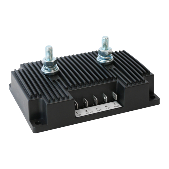
LEAB Automotive GmbH 5 About this Product 5 About this Product Fig. 1: CDR 12/24 V 1 PIN 1 LED (connection for ex- 2 PIN 2 BI/UNI (connection for ternal LED) changing the charging current distribution) 3 PIN 3 OFF (connection for activ-... -
Page 8: Assembly
6 Assembly LEAB Automotive GmbH Fig. 2: Dimensioned drawing CDR 12/24 V 6 Assembly NOTE! Maximum torque: 10 Nm To assemble the device, perform the following steps: ü Choose a cool, dry and well-ventilated assembly site. ü Do not mount the device directly next to or above batteries. -
Page 9: Installation
In vehicles with generator management, auxiliary batteries are not sufficiently charged by conventional cut-off relays or current dis- tributors. LEAB recommends installing the charge booster BPC 12-12/40 (part no.: 1041003001). To install the device, perform the following steps: NOTE! Maximum screw terminal torque: 20 Nm 1 Connect the positive terminal of the starter battery to screw terminal 1 (in- put). -
Page 10: Optional: Activate Bypass Function
7 Installation LEAB Automotive GmbH 7.1 Optional: Activate bypass function The bypass function (permanently ON) is used to charge the starter battery with the auxiliary battery if the voltage of the starter battery is too low. The voltage detection through PIN 5 (GND) is deactivated so that the CDR distrib- utes charging current at any voltage. -
Page 11: Optional: Activate Switch-Off Function
LEAB Automotive GmbH 7 Installation To change the direction of the charging current distribution to bidirectional, carry out the following step: 2 Disconnect the connection cable from plug contact PIN 2. ð The charging current distribution is bidirectional from screw terminal 1 to screw terminal 2 or vice versa, depending on where a higher voltage is... -
Page 12: Operation
– Should the voltage drop below 12.8 V or 25.6 V, the CDR will disconnect the batteries to prevent mutual discharge. Fig. 3: Switch-on / off voltage CDR 12/24 V 8.1 Operating status The external LED connected to the unit functions as a remote LED display and indicates the operating status. -
Page 13: Maintenance
The system must not be disposed of with household waste. Take it to a recycling point or return it to your point of sale. 11 EU Declaration of Conformity The CDR 12/24 V complies with the requirements of the following directives: – 2014/30/EU: EMV – 2011/65/EU: RoHS... - Page 14 11 EU Declaration of Conformity LEAB Automotive GmbH LEAB Automotive GmbH Thorshammer 6 24866 Busdorf...
- Page 15 LEAB Automotive GmbH 11 EU Declaration of Conformity LEAB Automotive GmbH Thorshammer 6 24866 Busdorf...
- Page 16 Tel: +49 (0) 4621 9 78 60-0 Fax: +49 (0) 4621 9 78 60-260 info@leab.eu It is prohibited to copy, duplicate, translate or otherwise pass on the content of this guide to third parties without the express written permission of LEAB.
Need help?
Do you have a question about the CDR 12/24 V and is the answer not in the manual?
Questions and answers