Table of Contents

Related Manuals for LEAB Clayton Power G3 Combi 1012-50


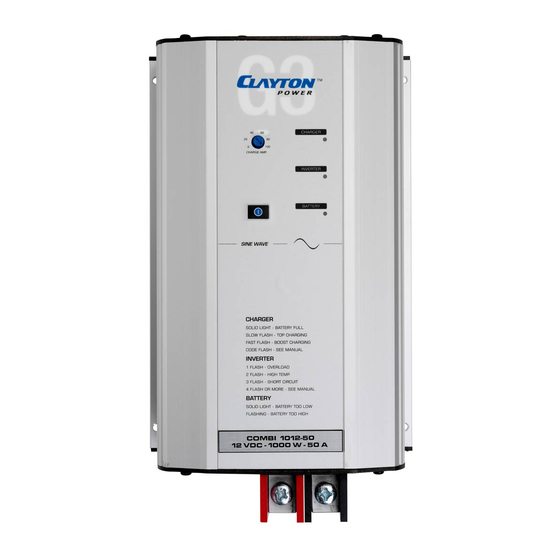
Summary of Contents for LEAB Clayton Power G3 Combi 1012-50
- Page 1 G3 Combi from 1012-50, 1024-30, 1312-80, 1512-80, 1524-40, 2012-100, 2324-50 Lightweight and compact sine wave inverter and battery charger User Manual LEAB Automotive GmbH User Manual Thorshammer 6 Version: 2.0 DE-24866 Busdorf Issue date: 12.02.2019...
-
Page 2: Table Of Contents
User Manual About this Manual Table of Contents About this Manual .................. 1 General Safety ..................2 Technical Specifications ................3 Package contents ..................6 About the Combi ..................7 Component Drawing and Description ............. 9 Mounting ....................10 Installation .................... 10 Normal Operation ................. -
Page 3: General Safety
User Manual General Safety Signal word Meaning Warns of imminent danger resulting in death or DANGER serious injury. Warns of a potentially dangerous situation that can WARNING result in death or serious injury. Warns of a potentially dangerous situation that can CAUTION result in moderate or minor injuries. -
Page 4: Technical Specifications
User Manual Technical Specifications Any modifications to the device or its components are prohibited and do not conform to its intended use. Observe the following safety instructions: Device defect due to incorrect installation: Install the device in a dry and cool location. - Page 5 User Manual Technical Specifications Model 1012-50 1312-80 1512-80 2012-100 Input voltage (DC) Nominal voltage of the 12 V battery Max. input voltage 15 V Switch-off voltage 10.5 V (Response time 3 s) Switch-off voltage (Response time < 10 s) Switch-on voltage (restart) 12.75 V Mechanical specification Protection class...
- Page 6 User Manual Technical Specifications 24-V Devices Model 1024-30 1524-40 2324-50 Output power Continuous power 1,000 W 1,500 W 2,300 W Overload (1 s) 2,000 W 3,000 W 3,000 W Overload (10 s) 1,500 W 1,800 W 3,000 W Overload (15 min) 1,200 W 1,700 W 2,500 W...
-
Page 7: Package Contents
User Manual Package Contents Model 1024-30 1524-40 2324-50 Battery Battery type Lead-acid (wet, gel AGM) and lithium Charging characteristic Temperature sensor (NTC) optional Max charging current 0-30 A 0-40 A 0-50 A (adjustable) Current reduction at 50°C Current reduction at 60°C Current reduction at 80°C Charging voltage (default setting) Main charging... -
Page 8: About The Combi
User Manual About the Combi 5 About the Combi Details Description On/off button Potentiometer charging current limitation in % Charger LED – green Inverter LED – blue Battery LED – red Page 7 of 22... - Page 9 User Manual About the Combi Control displays between the data slots Control displays Pos. Colour Function Green Illuminates when data connection is “high” Yellow Illuminates when data connection is “low” Orange Illuminates when remote switch “on” Not assigned Details Description AC input, Neutrik model –...
-
Page 10: Component Drawing And Description
User Manual Component Drawing and Description 6 Component Drawing and Description The pins for single wire communication are connected in parallel. Plug, RJ12 Signal Description -Temp X1 Temperature sensor (-) Ground Ground, consumer (fused) +Temp X1 Temperature sensor (+) Sync_In/Out Not assigned Data Single wire communication (Clayton) -
Page 11: Mounting
User Manual Mounting 7 Mounting To mount the device, perform the following steps: NOTICE Choose a cool, dry and well-ventilated mounting site. The device must be protected from dust and moisture. Do not mount the device directly next to or above batteries. ... - Page 12 User Manual Installation Connecting the Battery (DC Cable) To connect the battery, perform the following steps: Connect one DC cable to the negative terminal of the device. Connect one DC cable to the positive terminal of the device. Connect the negative terminal of the device to the negative terminal of the battery.
-
Page 13: Normal Operation
User Manual Normal Operation 9 Normal Operation Switching On The device is mounted and installed. To switch on the device, perform the following steps: Press the on/off button for 2 s. Red and blue LEDs illuminate. Red LED goes out. ... - Page 14 User Manual Functions Activating the Standby Mode To activate the standby mode, perform the following steps: The device is switched off. Press the on/off button until the blue and red LEDs illuminate. The standby mode is activated. Deactivating the Standby Mode To deactivate the standby mode, perform the following steps: The device is switched off.
- Page 15 Battery charging takes place with a 3-stage IU characteristic curve for gentle and optimum charging of the batteries. The characteristic curves can be adapted by LEAB to the batteries to be charged. Charging with constant current (I-phase, green LED flashes fast)
- Page 16 User Manual Functions Charging with constant voltage (U phase, green LED flashes slowly) In this phase the battery is fully charged. The voltage is kept constant at a value of 14.4 V (standard value). As the charge of the battery increases, the current decreases continuously and approaches a lower limit which depends on the type and size of the battery.
- Page 17 User Manual Functions Temperature Compensation (NTC Sensor) If an external temperature sensor (NTC) is connected, the charging voltage adapts to the battery voltage in relation to the ambient temperature. The figure shows the adjustment of the charging voltage in relation to the operating temperature (in degrees Celsius).
-
Page 18: Control Displays And Error Descriptions
User Manual Control Displays and Error Descriptions 11 Control Displays and Error Descriptions Blue LED Description Steady light Inverter in operation …..…..…..…..….. Start mode – Load adjustment ....…....... Output overloaded ....……... Operating temperature too high (automatic cooling and restart) ....…….. Short-circuit at the inverter output ....... -
Page 19: Maintenance
User Manual Maintenance All LEDs Description Flickering Remote and mains switch on the device at the same time ....…....... NTC error (internal temperature sensor) ....……... Overvoltage in the internal high-voltage DC connection ....…….. Defect in half of the bridge circuit ....... -
Page 20: Disposal
15 EU Declaration of Conformity The G3 Combi in models 1012-50, 1024-30, 1312-80, 1512-80, 1524-40, 2012-100, 2324-50 complies with the requirements of the following directives: 2014/30/EC: 2014/35/EC: 2011/65/EC: RoHS The current and complete document is available on request from techdoc@leab.eu. Page 19 of 22... - Page 21 User Manual Appendix: Use of Lead-acid Batteries Appendix: Use of Lead-acid Batteries Selection of the Battery Select a deep-cycle battery (e.g. lead-gel battery) as the power source for the inverter. These batteries are designed for higher continuous loads and cyclical discharges of up to 80% of their capacity without damaging the battery.
- Page 22 User Manual Connecting Batteries in Series Connecting Batteries in Series 2 batteries connected in series provide double the supply voltage. However, the total capacity does not increase. Example: 2 batteries 12 V / 100 Ah connected in series provide a supply voltage of 24 V with 100 Ah.
- Page 23 User Manual Topping up Acid Level Topping up Acid Level Ensure that the cell grids are always covered with acid. Always use distilled water to top up the battery, never normal drinking or sea water. Follow the manufacturer's instructions when topping up the acid level. Storing the Battery ...
- Page 24 LEAB Automotive GmbH Thorshammer 6 DE-24866 Busdorf Germany Tel.: +49(0) 4621 9 78 60-0 Fax: +49(0) 4621 9 78 60-260 Email: anfrage@leab.eu Web: www.leab.eu...