Table of Contents
Advertisement
Quick Links
User's Manual
993-603
Revision A: October, 1996
WELDING POWER SUPPLIES
IP-215A
IP-215A/RS485
IP-217A
IP-217A/RS485
WARNING: Please be sure to read all personnel and
equipment safety precautions noted in this manual.
Prepared by
IP-215A AND IP-217A
FINE SPOT
Model
Copyright © 1996
Unitek Miyachi Corporation
All Rights Reserved
Definition
Standard 50 Amp Power
Supply
50 Amp Power Supply
With RS-485 Data Port
Standard 200 Amp Power
Supply
200 Amp Power Supply
With RS-485 Data Port
Unitek Miyachi Corporation
1820 South Myrtle Avenue
Monrovia, CA 91017-7133
Phone (818) 303-5676
FAX (818) 358-8048
TWX (910) 585-1836
Advertisement
Table of Contents

Related Manuals for Unitek Miyachi IP-215A

Summary of Contents for Unitek Miyachi IP-215A
- Page 1 User's Manual 993-603 Revision A: October, 1996 IP-215A AND IP-217A FINE SPOT WELDING POWER SUPPLIES Model Definition IP-215A Standard 50 Amp Power Supply IP-215A/RS485 50 Amp Power Supply With RS-485 Data Port IP-217A Standard 200 Amp Power Supply IP-217A/RS485 200 Amp Power Supply...
- Page 2 IP-215A and IP-217A Fine Spot Welding Power Supplies User's Manual 993-603, October 1996, Revision A Unitek Miyachi Corporation 1820 South Myrtle Avenue Monrovia, CA 91017-7133 Phone (818) 303-5676 FAX (818) 358-8048 TWX (910) 585-1836...
- Page 3 ©1996, Unitek Miyachi Corporation The engineering designs, drawings and data contained herein are the proprietary work of UNITEK MIYACHI CORPORATION and may not be reproduced, copied, exhibited or otherwise used without the written authorization of UNITEK MIYACHI CORPORATION. Printed in the United States of America...
- Page 4 Do not be misled by the term low voltage. Potentials as low as 50 volts may cause death under adverse conditions. PLEASE READ THE SAFETY STEPS ON THE NEXT PAGE IP-215A/IP-217A FINE SPOT WELDING POWER SUPPLIES 993-603 REV A: October, 1996...
- Page 5 Send for medical help as soon as possible. When the victim is free of contact with the source of electrical shock, move the victim away and start artificial resuscitation. IP-215A/IP-217A FINE SPOT WELDING POWER SUPPLIES 993-603 REV A: October, 1996...
-
Page 6: Table Of Contents
POWER Circuit Breaker ......... 4-10 IP-215A/IP-217A FINE SPOT WELDING POWER SUPPLIES... - Page 7 Technical Assistance ........... 7-3 IP-215A/IP-217A FINE SPOT WELDING POWER SUPPLIES...
- Page 8 ILLUSTRATIONS IP-215A Fine Spot Welding Power Supply ......2-1 Using the Power Supply With Multiple Welding Transformers ... . 2-3 Standard Connection Diagram .
-
Page 9: About This Manual
CHAPTER 1 ABOUT THIS MANUAL This manual is organized to assist you in getting productive quickly with the IP-215A or IP- 217A High Frequency Inverter Welding Power Supply. The simplified information and instructions in Chapters 1 through 3 will allow you to get the equipment up and running safely and efficiently, and make basic welds. -
Page 10: Referencing Conventions
CHAPTER 1: ABOUT YOUR MANUAL Referencing Conventions For ease of referencing the related components of the IP-215A/IP-217A High Frequency Inverter Welding Power Supply, here is the way that they will be referred to in the rest of the narrative in this manual:... -
Page 11: If You Need Assistance
If you need further assistance, please contact our sales representative in your area, or contact the factory directly at: Unitek Miyachi Corporation 1820 South Myrtle Avenue Monrovia, California 91017-7133 Telephone: (818) 303-5676 Fax: (818) 358-8048 IP-215A/IP-217A FINE SPOT WELDING POWER SUPPLIES 993-603 REV A: October, 1996... -
Page 13: Chapter 2 About Your Equipment
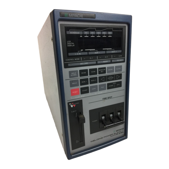
CHAPTER 2 ABOUT YOUR EQUIPMENT Overview The IP-215A/IP-217A is a high frequency inverter resis- tance welding power supply designed for fine spot welding of precision parts. Figure 2-1 shows the physi- cal characteristics of the 215 Power Supply. The 217 Power Supply is identical except for minor differences in the front panel key locations. -
Page 14: Welding Schedules
The Power Supply is delivered fully assembled, together with a shipping kit containing parts that you will need to install, operate and maintain it. The parts included in the shipping kit are as follows: Power Cable Output (Welding Transformer) Cable IP-215A/IP-217A FINE SPOT WELDING POWER SUPPLIES 993-603 REV A: October, 1996... -
Page 15: Using The Power Supply With Multiple Welding Transformers
CHAPTER 2: ABOUT YOUR EQUIPMENT Sense Cable Data I/O Cable IP2MA600.WPG Figure 2-2. Using the Power Supply With Multiple Welding Transformers I/O Cable Connector User’s Manual, Part No. 993-603 IP-215A/IP-217A FINE SPOT WELDING POWER SUPPLIES 993-603 REV A: October, 1996... -
Page 17: Chapter 3 Getting Started
Power Supply shows no sign of damage. Standard Installation The standard Power Supply/Welding Transformer installation is shown in Figure 3-1. Depending on your welding application, you will require an appropriate welding transformer (see Appendix IP-215A/217A FINE SPOT WELDING POWER SUPPLIES 993-603 REV A: October, 1996... -
Page 18: Standard Connection Diagram
The factory wiring of the Power Supply I/O connector allows the weld head firing microswitch to send a single START signal for each operation of the footswitch. For other START switch selections, please refer to Appendix B. IP-215A/217A FINE SPOT WELDING POWER SUPPLIES 993-603 REV A: October, 1996... -
Page 19: Making A Trial Weld
Making a production weld results from making several trial welds, testing the welds, then adjust- ing the selected welding parameters each time until you reach production weld quality. The opera-ting controls and the display are described in Chapter 4. Detailed operating instructions for IP-215A/217A FINE SPOT WELDING POWER SUPPLIES 993-603 REV A: October, 1996... - Page 20 Weld 1 Time (W1): 10 ms Cool Time (CO): 0 ms Weld 2 Current Rise Time (R2): 0 ms Weld 2 Time (W2): 0 ms Control Feedback Mode (I.F.W): Constant Current (I) IP-215A/217A FINE SPOT WELDING POWER SUPPLIES 993-603 REV A: October, 1996...
- Page 21 2. Set the Weld 1 time to double the previous setting and reduce Weld 1 current by 50%. Repeat steps 1 and 2 until you achieve a satisfactory weld. IP-215A/217A FINE SPOT WELDING POWER SUPPLIES 993-603 REV A: October, 1996...
-
Page 23: Chapter 4 Controls
Figure 4-1. Rear Panel Components Ventilation Grill: Exhaust vent for heated air from the housing interior. CAUTION: Do not block this ventilation. Overheating of the electronic circuitry can cause permanent damage. IP-215A/IP-217A FINE SPOT WELDING POWER SUPPLIES 993-603 REV A: October, 1996... -
Page 24: Front Panel Components
(enter or change) and read welding values and program settings. The display editing keys are the CURSOR and DATA keys. The display screen has two lines of 20 character IP-215A/IP-217A FINE SPOT WELDING POWER SUPPLIES 993-603 REV A: October, 1996... -
Page 25: Front Panel Controls And Display
CHAPTER 4: CONTROLS IP2FRONT.WPG Figure 4-2. Front Panel Controls and Display IP-215A/IP-217A FINE SPOT WELDING POWER SUPPLIES 993-603 REV A: October, 1996... -
Page 26: Control Mode Status Indicators
There is a system problem. Weld Program Key Field. There are five keys in this field that contribute to the selection of weld program values and settings. Pressing this key accesses the Weld IP-215A/IP-217A FINE SPOT WELDING POWER SUPPLIES 993-603 REV A: October, 1996... - Page 27 (monitor Weld 2 current). VM: Voltage monitor selection, shown here as 0 (voltage monitor off). Other selections are 1 (monitor Weld 1 voltage) and 2 (monitor Weld 2 voltage). IP-215A/IP-217A FINE SPOT WELDING POWER SUPPLIES 993-603 REV A: October, 1996...
- Page 28 215A or 0 through 5 for the IP-217A) with the DATA key. D—OUT=OFF: Status of the Data I/O port, shown here as OFF. To enable data output through the port, toggle OFF to ON with the DATA key. IP-215A/IP-217A FINE SPOT WELDING POWER SUPPLIES 993-603 REV A: October, 1996...
- Page 29 -: Lower limit designator 0.00KA: Lower current limit set for Weld Schedule 7 0.00V: Lower voltage limit set for Weld Schedule 7 0.00KW: Lower power limit set for Weld Schedule 7 IP-215A/IP-217A FINE SPOT WELDING POWER SUPPLIES 993-603 REV A: October, 1996...
-
Page 30: Weld Control Key Field
WI: Weld 1 12.36KA: Actual weld current delivered for Weld 1 5.33V: Actual transformer secondary winding voltage developed for Weld 1 9.42KW: Actual welding power delivered for Weld 1 IP-215A/IP-217A FINE SPOT WELDING POWER SUPPLIES 993-603 REV A: October, 1996... - Page 31 The COUNT key, when pressed by itself, accesses the Weld Count display screen. This display screen allows you to monitor the number of welds (shown here as WELD COUNT = 04589) IP-215A/IP-217A FINE SPOT WELDING POWER SUPPLIES 993-603 REV A: October, 1996...
-
Page 32: Welcard Drive
POWER Circuit Breaker. The POWER circuit breaker is the main power switch for the Power Supply. It also provides power overload protection (50 A) to the AC power input circuit. IP-215A/IP-217A FINE SPOT WELDING POWER SUPPLIES 4-10 993-603 REV A: October, 1996... -
Page 33: Chapter 5 Operating Your Power Supply
With the -DOWN DATA and UP+ DATA keys, scroll through the three selections of I, V, and W. The character that you leave selected will be your choice of control modes. IP-215A/IP-217A FINE SPOT WELDING POWER SUPPLIES 993-603 REV A: October, 1996... -
Page 34: Display Data Entry Ranges
0 - 5 (217) Units Welding Transformer Channel Programming (SCAN Key) Scan Count 0 - 4 Units Scan Interval Time 0 - 990 msec Table 5-1. Display Data Entry Ranges (continued) IP-215A/IP-217A FINE SPOT WELDING POWER SUPPLIES 993-603 REV A: October, 1995... -
Page 35: Setting The Weld Schedule
With the DATA keys, enter the example rise value of 2 milliseconds (02). With the CURSOR keys, move the cursor to the display W1 field (weld time for Weld 1). IP-215A/IP-217A FINE SPOT WELDING POWER SUPPLIES 993-603 REV A: October, 1996... -
Page 36: Monitoring Power Supply Operation
Monitoring Weld Heat Limits. Assume that you wish to monitor the weld heat limits for the example weld schedule that you previously programmed in this chapter under IP-215A/IP-217A FINE SPOT WELDING POWER SUPPLIES 993-603 REV A: October, 1995... - Page 37 With the DATA keys, enter 0.95. With the example of monitoring with the deviations that you set and 1.0 KA of programmed weld current, limit errors are illustrated as follows: IP2LIM.WPG IP-215A/IP-217A FINE SPOT WELDING POWER SUPPLIES 993-603 REV A: October, 1996...
-
Page 38: Current Setting Monitor (Ip-217A Only)
TROUBLE signal will be output through the I/O connector. The display screen will display the alarm message FULL WAVE !!. Operation will be restored by the next START signal or TROUBLE RESET signal input through the I/O connector. IP-215A/IP-217A FINE SPOT WELDING POWER SUPPLIES 993-603 REV A: October, 1995... -
Page 39: Automatic Performance Monitors
RESET key; or, an error reset signal may be supplied externally through the I/O interface at pins 6 and 7 (refer to Appendix B). IP-215A/IP-217A FINE SPOT WELDING POWER SUPPLIES 993-603 REV A: October, 1996... -
Page 40: Selecting The Welding Transformer (217 Power Supply Only)
With the DATA keys, enter a suitable time interval for channels 1 and 2. The interval defines the period between the firing of each weld transformer. Refer to the welding transformer timing diagram in Appendix B. IP-215A/IP-217A FINE SPOT WELDING POWER SUPPLIES 993-603 REV A: October, 1995... -
Page 41: Selecting The Weld Count
You may adjust the response speed (gain) of the control feedback in any of the three control feed-back modes: Constant Current, Constant Voltage, or Constant Power. The value that you IP-215A/IP-217A FINE SPOT WELDING POWER SUPPLIES 993-603 REV A: October, 1996... -
Page 42: Activating The Data Output Port
NOTE: Keep the D—OUT = OFF setting if the data output option is not installed or when it is not communicating with a host computer. IP-215A/IP-217A FINE SPOT WELDING POWER SUPPLIES 5-10 993-603 REV A: October, 1995... -
Page 43: Chapter 6 Using The Welcard
3. The battery is a Panasonic 3V BR2016, or equivalent. Its life is five years. We recommend that you replace the battery more frequently. 4. When you replace the battery, observe the correct polarity. IP-215A/IP-217A FINE SPOT WELDING POWER SUPPLIES 993-603 REV A: October, 1996... -
Page 44: Welcard Data Records
Welcard types. The only difference in the procedures is the key selection of the Welcard type (Schedule, Monitor 1, or Monitor 2). To initialize the Welcard: IP-215A/IP-217A FINE SPOT WELDING POWER SUPPLIES 993-603 REV A: October, 1996... -
Page 45: Referencing The Directory
Referencing the Directory. This function displays the name of the Welcard set during the initialization operation. For a schedule Welcard, the recording status will be displayed, and you can set write protection ON and OFF. To reference the directory: IP-215A/IP-217A FINE SPOT WELDING POWER SUPPLIES 993-603 REV A: October, 1996... -
Page 46: Copying A Schedule To A Welcard
Supply (IP-215A). With the CURSOR keys, move the cursor to the bottom display screen line (IP215A CARD) and press the ENTRY key to change copy direction. This action will access Copy Direction confirmation display screen. IP-215A/IP-217A FINE SPOT WELDING POWER SUPPLY... -
Page 47: Copying A Schedule To The Power Supply
Step 1. With the CURSOR keys, move the cursor to the file number (F) field and key in a source file number from 1 to 13. IP-215A/IP-217A FINE SPOT WELDING POWER SUPPLIES 993-603 REV A: October, 1996... -
Page 48: Welcard System Error Messages
3. Card battery is dead. Replace the battery and format the card. COPY FROM 1. Unformatted card is Format the card. UNFORMATTED CARD installed. IMPOSSIBLE !! 2. Card battery is dead. Replace the battery and format the card. IP-215A/IP-217A FINE SPOT WELDING POWER SUPPLY... - Page 49 Card copying is selected but Replace the Monitor Card CARD IMPOSSIBLE!!` a Monitor Card is installed. with a Schedule Card or reinitialize the installed card as a Schedule Card. IP-215A/IP-217A FINE SPOT WELDING POWER SUPPLIES 993-603 REV A: October, 1996...
-
Page 51: Chapter 7 In Case Of Difficulty
CHAPTER 7 IN CASE OF DIFFICULTY Your IP-215A and IP-217A Fine Spot Welding Power Supplies are designed with reliability as a top user priority. But, occasionally, you will run into a problem and need some help to get back to normal operation. Reading this chapter will speed up the process. -
Page 52: Adjusting Display Viewing Angle
7-1). You may adjust the angle with the CONTRAST screwdriver adjustment on the rear panel. Turn-ing the adjustment clockwise and counterclockwise moves the viewing angle downward and upward respectively. Memory Backup Battery Replacement IP-215A/IP-217A FINE SPOT WELDING POWER SUPPLIES 993-603 REV A: October, 1996... -
Page 53: Technical Assistance
The lithium memory backup battery is located at the bottom center of the Power Supply main printed circuit board (see Figure 7-2). Although the battery’s operational life is five years, we recommend that you replace this battery routinely every three years. Technical Assistance IP-215A/IP-217A FINE SPOT WELDING POWER SUPPLIES 993-603 REV A: October, 1996... - Page 54 If you need further technical assistance, please contact either your authorized service agent or: UNITEK MIYACHI CORPORATION 1820 South Myrtle Avenue Monrovia, CA 91017-7133 Phone: (818) 303-5676 FAX: (818) 358-8048 TWX: (910) 585-1836 IP-215A/IP-217A FINE SPOT WELDING POWER SUPPLIES 993-603 REV A: October, 1996...
-
Page 55: Technical Specifications
APPENDIX A Technical Specifications IP-215A/217A FINE SPOT WELDING POWER SUPPLIES 993-603 REV A: October, 1996... - Page 56 Input Power Line Voltage Range ....220 VAC, ±10%, 3 Phase, 50/60 Hz Input Power Line Current (peak maximum) ......IP-215A: 50A IP-217A: 200A Control Frequency .
- Page 57 Depth ........
- Page 58 Mode Selection Settings for Each Weld Schedule (continued): Feedback Gain Adjustment (C-GAIN=) ..... . . IP-215A: (0) - (9) IP-217A: (0) - (5) Data Output (D-OUT=) .
-
Page 59: Cable Wiring And Signal Specifications
APPENDIX B Cable Wiring Signal Specifications IP-215A/IP-217A FINE SPOT WELDING POWER SUPPLIES 993-603 REV A: October, 1996... - Page 60 Power Cable Wiring and Interconnections The Power Supply AC input cable is supplied in the shipping kit. The cable wiring and interconnections for the IP-215A and IP-217A are as follows: IP-215A/IP-217A FINE SPOT WELDING POWER SUPPLIES 993-603 REV A: October, 1996...
- Page 61 Welding Transformer Cable Connections The welding transformer AC input and voltage sensing cables are supplied in the shipping kit. The cable wiring and interconnections for the IP-215 and IP-217A are as follows: IP-215A/IP-217A FINE SPOT WELDING POWER SUPPLIES 993-603 REV A: October, 1996...
- Page 62 CABLE WIRING AND SIGNAL SPECIFICATIONS Welding Transformer Cable Connections (continued) IP-215A/IP-217A FINE SPOT WELDING POWER SUPPLIES 993-603 REV A: October, 1996...
- Page 63 CABLE WIRING AND SIGNAL SPECIFICATIONS Welding Transformer Cable Connections (continued) IP-215A/IP-217A FINE SPOT WELDING POWER SUPPLIES 993-603 REV A: October, 1996...
- Page 64 The pin-in/pin-out diagram to the right of the I/O connector shows the input signal (pins 1 through 13) and output signal (pins 15 through 20) schematics. START Inputs. The START signals initiate the weld cycle. Use normally open, dry IP-215A/IP-217A FINE SPOT WELDING POWER SUPPLIES 993-603 REV A: October, 1996...
- Page 65 START signal is shorter than 20 milliseconds, the weld cycle will not start. As shown in the timing diagram on the following page, Weld Schedule 3 is being selected since START 1 and START 3 are turned ON within the 20-millisecond window. IP-215A/IP-217A FINE SPOT WELDING POWER SUPPLIES 993-603 REV A: October, 1996...
- Page 66 The schedule selection and start scheme is shown in the following table: Weld Schedule Number Weld Schedule Start Type 4-Schedule (7S = 0): START 1 START 2 START 3 START 4 Signal is ON (Closed) IP-215A/IP-217A FINE SPOT WELDING POWER SUPPLIES 993-603 REV A: October, 1996...
- Page 67 The timing diagram for four welding transformers results from a SCAN = 4 setting on the Mode Selection display screen. You select the scan interval time also with this display screen. IP-215A/IP-217A FINE SPOT WELDING POWER SUPPLIES 993-603 REV A: October, 1996...
- Page 68 CABLE WIRING AND SIGNAL SPECIFICATIONS IP-215A/IP-217A FINE SPOT WELDING POWER SUPPLIES B-10 993-603 REV A: October, 1996...
- Page 69 ON/OFF sequence through an external, normally closed switch. With the WELD switch open, no weld current flows but the weld sequence is executed. Count Up Output IP-215A/IP-217A FINE SPOT WELDING POWER SUPPLIES 993-603 REV A: October, 1996 B-11...
- Page 70 Power Supply. The cable transfers welding transformer channel select signals from the Power Supply to the welding transformers. The cable also supplies 220 VAC power to the IP-215A/IP-217A FINE SPOT WELDING POWER SUPPLIES B-12 993-603 REV A: October, 1996...
- Page 71 NOTE: If welding transformer over-temperature sensor is not connected, you must jumper pins 5 and 13. Otherwise, you will not be able to start the weld cycle. IP-215A/IP-217A FINE SPOT WELDING POWER SUPPLIES 993-603 REV A: October, 1996 B-13...
-
Page 73: Welding Transformer Specifications
APPENDIX C Welding Transformer Specifications IP-215A/IP-217A FINE SPOT WELDING POWER SUPPLIES 993-603 REV A: October, 1996... - Page 74 183/7.2 183/7.2 155/6.1 Height (mm/in.) 176/6.9 176/6.9 184/7.2 184/7.2 184/7.2 105/4.1 Depth 280/11.0 295/11.6 340/13.4 360/14.2 410/16.1 300/11.8 NOTES: With 15-cycle weld time At 5.7 liters (1.5 U.S. gallons)/minute IP-215A/IP-217A FINE SPOT WELDING POWER SUPPLIES 993-603 REV A: October, 1996...
-
Page 75: Resistance Welding Basics
APPENDIX D Resistance Welding Basics IP-215A/IP-217A FINE SPOT WELDING POWER SUPPLIES 993-603 REV A: October, 1996... - Page 76 (I), the total electrical resistance (R ), and the weld time (t), and is inversely proportional to the contact area (A). Welding Parameter Interaction Figure D-1. Interaction between welding parameters. IP-215A/IP-217A FINE SPOT WELDING POWER SUPPLIES 993-603 REV A: October, 1996...
- Page 77 Magnesium Brass -2, -14 Constantan Alumimun Cold Rolled Steel Brass -2, -14 Copper Alumimun Stainless Steel Brass -2, -14 Tinned Copper Beryllium Beryllium Copper Copper Brass -2, -14 Dumet IP-215A/IP-217A FINE SPOT WELDING POWER SUPPLIES 993-603 REV A: October, 1996...
- Page 78 Consil Gold Gold Consil Tinned Copper Gold Kovar Consil Dumet Hastalloy Titanium Constantan Constantan Inconel Inconel Constantan Copper Inconel Kulgrid Constantan Tinned Copper Invar Invar Constantan Iron Iridium Iridium IP-215A/IP-217A FINE SPOT WELDING POWER SUPPLIES 993-603 REV A: October, 1996...
- Page 79 Stainless Steel Nickel Nickel Nickel Cold Rolled Steel Nickel Stainless Steel Nickel Tantalum Nickel Tungsten Nickel Alloy Nickel Alloy Nickel Alloy Tinned Brass Nickel Alloy Beryllium Copper Nickel Alloy Consil IP-215A/IP-217A FINE SPOT WELDING POWER SUPPLIES 993-603 REV A: October, 1996...
- Page 80 For less critical applications, a file can be used to clean a badly damaged tip. However, after filing, polishing disks should then be used to ensure that the IP-215A/IP-217A FINE SPOT WELDING POWER SUPPLIES 993-603 REV A: October, 1996...
- Page 81 Polarity, as determined by the direction of weld current flow, can have a marked effect on the weld characteristics of some material combinations. This effect occurs when welding materials with large differences in resistivity, such as copper and nickel or when welding IP-215A/IP-217A FINE SPOT WELDING POWER SUPPLIES 993-603 REV A: October, 1996...
- Page 82 Repeat steps 1 and 2 for different weld forces and then create a plot of part pull strength versus weld current for different weld forces as shown in Figure D-2. Repeat steps 1 through 3 using a different, but fixed weld time. Weld Strength Profile IP-215A/IP-217A FINE SPOT WELDING POWER SUPPLIES 993-603 REV A: October, 1996...
- Page 83 Figure D-2. Weld Strength Profile. might show that they could be consolidated into one or two weld schedules. This would have obvious manufacturing advantages. IP-215A/IP-217A FINE SPOT WELDING POWER SUPPLIES 993-603 REV A: October, 1996...
-
Page 85: Alarm Message List
APPENDIX E Alarm Message List IP-215A/IP-217A FINE SPOT WELDING POWER SUPPLIES 993-603 REV A: October, 1996... - Page 86 Error Reset: Close the RESET input peak output current exceeded 50 A for signal at the I/O connector (refer to Ap- the IP-215A or 200 A for the IP-217A pendix B). during the weld cycle. Remedies: Check for a short circuit...
- Page 87 Remedies: Check for problems in the MR = 1: END signal is not welding cables, work pieces, the weld output at I/O head, and the AC input voltage source. connector. Next weld cannot begin. IP-215A/IP-217A FINE SPOT WELDING POWER SUPPLIES 993-603 REV A: October, 1996...
- Page 88 APPENDIX E: ALARM MESSAGE LIST CURRENT ERROR !! Current Upper Limit Exceeded. Error Reset: HIGHER THAN LIMIT When the weld is completed, the meas- MR = 0: Next START signal ured current value has gone above the auto-matically clears current monitor upper limit setting. error con-dition.
- Page 89 B). Next weld can begin. Remedies: Check for problems in the work pieces and the weld head. MR = 1: END signal is not output at I/O connector. Next weld cannot begin. IP-215A/IP-217A FINE SPOT WELDING POWER SUPPLIES 993-603 REV A: October, 1996...
- Page 90 APPENDIX E: ALARM MESSAGE LIST FULL WAVE !! Control Limit Exceeded. The control Error Reset: Close the RESET input pulse width was 100% for more than 5 signal at the I/O connector or wait for msec during the weld cycle. the next START signal to automatically clear the error condition.
-
Page 91: Weld Programming Sheets
You will find the schedule sheets in this appendix useful for planning or recording your Power Supply weld mode and weld parameter selections. You may wish to reproduce a supply of blanks. IP-215A/IP-217A FINE SPOT WELDING POWER SUPPLIES 993-603 REV A: October, 1996... - Page 92 I = Current Control Mode V = Voltage W = Power HEAT 1: Current Mode Voltage Mode Power Mode HEAT 2: Current Mode Voltage Mode Power Mode MODE SELECTION SCHEDULE IP-215A/IP-217A FINE SPOT WELDING POWER SUPPLIES 993-603 REV A: October, 1996...
- Page 93 1 = ON 0 = 4 Schedule 1 = 7 Schedule 0 = External Start 1 = Panel Start 0 = Change Schedule 1 = No Change Schedule MONITOR LIMITS SCHEDULE IP-215A/IP-217A FINE SPOT WELDING POWER SUPPLIES 993-603 REV A: October, 1996...
- Page 94 Transformer Scan Count (COUNT = ) Transformer Interval Time (INTERVAL TIME = Weld Counter (SET COUNT = ) Transformer Type (TRANSFORMER = ) Control Gain (C—GAIN = ) Data Output (D—OUT = ) (Option) IP-215A/IP-217A FINE SPOT WELDING POWER SUPPLIES 993-603 REV A: October, 1996...
- Page 95 Similarly, the subject Mode Section Display Screen is listed under -M- , and under -D- as Display screens: Mode selection, and under -S- as Screens, display: Mode selection. IP-215A/IP-217A FINE SPOT WELDING POWER SUPPLIES 993-603 REV A: October, 1996 Index-1...
- Page 96 Monitor limits (4-7) Constant current feedback mode, general Welcard card name (6-3) (2-1) Welcard card type (6-3) Constant power feedback mode, general Weld heat (4-8) (2-2) Weld schedule (4-5)(5-3) IP-215A/IP-217A FINE SPOT WELDING POWER SUPPLIES Index-2 993-603 REV A: October, 1996...
- Page 97 MODE (4-5) File number selection display screen, MON. 1 (4-8) Welcard (6-5) MON. 2 (4-9) Firing switch input (3-2)(B-7) MONITOR SET (4-7) RESET (4-9) SCAN (4-7) WELD SCHED (4-5) IP-215A/IP-217A FINE SPOT WELDING POWER SUPPLIES 993-603 REV A: October, 1996 Index-3...
- Page 98 Referencing the Welcard directory (6-3) Related manuals (1-2) RESET key (4-9) Resistance welding basics (D-1) Revision Record (i) No current monitor (5-7) RS-485 connector (5-10) No voltage monitor (5-7) Nomenclature usage (1-2) IP-215A/IP-217A FINE SPOT WELDING POWER SUPPLIES Index-4 993-603 REV A: October, 1996...
- Page 99 System controls (4-1) Data records (6-2) System electrical specifications (A-2) Directory referencing (6-3) System status indicators (4-4) Error messages (6-6) File number confirmation display screen (6-6) -W- (continued) IP-215A/IP-217A FINE SPOT WELDING POWER SUPPLIES 993-603 REV A: October, 1996 Index-5...
- Page 100 Welding transformer specifications (C-1) Weld program key field (4-4) Welding transformer thermostat monitor Weld programming sheets (F-1) (5-7) WELD SCHED key (4-5) Welding transformer to weld head connections (3-2) IP-215A/IP-217A FINE SPOT WELDING POWER SUPPLIES Index-6 993-603 REV A: October, 1996...
Need help?
Do you have a question about the IP-215A and is the answer not in the manual?
Questions and answers