
Subscribe to Our Youtube Channel
Related Manuals for Moxa Technologies EDS-208 series


Summary of Contents for Moxa Technologies EDS-208 series
-
Page 1: Moxa Etherdevice Switch
Moxa EtherDevice Switch EDS-208 Series Hardware Installation Guide Second Edition, June 2008 © 2008 Moxa Inc., all rights reserved. Reproduction without permission is prohibited. P/N: 1802002080000... -
Page 2: Package Checklist
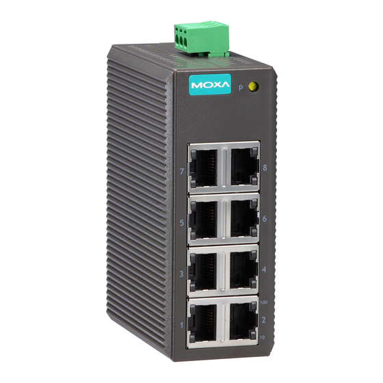
Overview The EDS-208 series of Moxa EtherDevice™ Switches are entry-level 8-port Ethernet Switches that provide a cost-effective solution for industrial Ethernet connections. EDS-208 provides a choice of 12 to 45 VDC power input or 18 to 30 VAC. The switches can operate reliably in a temperature range of -10 to 60°C, and the rugged hardware design makes EDS-208 perfect for ensuring that your Ethernet equipment can be used in demanding industrial environments. - Page 3 Panel Layout of EDS-208 Top View 1. Heat dissipation orifices 2. Terminal block for power input and grounding 3. Moxa Logo 4. Power input LED 5. 10/100BaseT(X) Port 24 VDC/VAC 6. TP port’s 100 Mbps LED 7. TP port’s 10 Mbps LED 8.
- Page 4 Panel Layout of EDS-208-M-SC/ST Top View Heat dissipation orifices Terminal block for power input and grounding Moxa Logo Power input LED 10/100BaseT(X) Port 24 VDC/VAC TP port’s 100 Mbps LED TP port’s 10 Mbps LED FX port’s 100 Mbps LED 100BaseFX Port 10.
-
Page 5: Mounting Dimensions (Unit = Mm)
Mounting Dimensions (unit = mm) 10.5 40.03 100M 24 VDC/VAC 86.5 40.03 EDS-208 EDS-208-M-SC/ST Side View Front View Rear View Top View DIN-Rail Mounting The plastic DIN-Rail attachment plate should already be fixed to the rear panel of EDS-208 when you take it out of the box. If you need to reattach the DIN-Rail attachment plate to EDS-208, make sure the DIN-Rail kit is situated towards the top, as shown in the figures below. -
Page 6: Wiring Requirements
Wiring Requirements ATTENTION Safety First! Be sure to disconnect the power cord before installing and/or wiring your EDS-208. Calculate the maximum possible current in each power wire and common wire. Observe all electrical codes dictating the maximum current allowable for each wire size. If the current goes above the maximum ratings, the wiring could overheat, causing serious damage to your equipment. -
Page 7: Wiring The Power Inputs
Wiring the Power Inputs The two left-most contacts of the 3-contact terminal block connector on EDS-208’s top panel are used for both the DC and AC inputs of EDS-208. Top and front views of one of the terminal block connectors are shown here. STEP 1: Insert the negative/positive DC or AC wires into the V-/V+ terminals. -
Page 8: 100Basefx Ethernet Port Connection
RJ45 (8-pin) to RJ45 (8-pin) Cross-Over Cable Wiring 100BaseFX Ethernet Port Connection The concept behind the SC/ST port and cable is quite straightforward. Suppose you are connecting devices I and II. Contrary to electrical signals, optical signals do not require a circuit in order to transmit data. Consequently, one of the optical lines is used to transmit data from device I to device II, and the other optical line is used to transmit data from device II to device I, for full-duplex transmission. -
Page 9: Led Indicators
LED Indicators The front panel of EDS-208 contains several LED indicators. The function of each LED is described in the table below. Color State Description Power is being supplied to the power input AMBER Power is not being supplied to the power input TP port’s 10 Mbps link is active Data is being transmitted at 10... -
Page 10: Switching, Filtering, And Forwarding
Switching, Filtering, and Forwarding Each time a packet arrives at one of the switched ports, a decision is made either to filter or to forward the packet. Packets with source and destination addresses belonging to the same port segment will be filtered, constraining those packets to one port, and relieving the rest of the network from the need to process them. - Page 11 Optical Fiber Multi mode Distance 5 km Wavelength, nm 1300 Min. TX Output, dBm Max. TX Output, dBm Sensitivity, dBm -34 to -30 Recommended Diameter (Core/Cladding) μm 50/125 (1 dB/km, 800 MHz × km) Power Input Voltage 12 to 45 VDC, 18 to 30 VAC (47 to 63 Hz) Input Current @ 24 VDC 0.14 A (EDS-208) 0.23 A (EDS-208-M-SC/EDS-208-M-ST)
- Page 12 Technical Support Contact Information www.moxa.com/support Moxa Americas: Moxa China (Shanghai office): Toll-free: 1-888-669-2872 Toll-free: 800-820-5036 Tel: +1-714-528-6777 Tel: +86-21-5258-9955 Fax: +1-714-528-6778 Fax: +86-10-6872-3958 Moxa Europe: Moxa Asia-Pacific: Tel: +49-89-3 70 03 99-0 Tel: +886-2-8919-1230 Fax: +49-89-3 70 03 99-99 Fax: +886-2-8919-1231 - 12 -...
Need help?
Do you have a question about the EDS-208 series and is the answer not in the manual?
Questions and answers