Table of Contents
Advertisement
Quick Links
Quick Installation Guide
Moxa Americas:
Toll-free: 1-888-669-2872
Tel:
1-714-528-6777
Fax:
1-714-528-6778
Moxa Europe:
Tel:
+49-89-3 70 03 99-0
Fax:
+49-89-3 70 03 99-99
Moxa India:
Tel:
+91-80-4172-9088
Fax:
+91-80-4132-1045
TN-G4500 Series
Moxa ToughNet Switch
Version 1.0, May 2020
Technical Support Contact Information
www.moxa.com/support
2020 Moxa Inc. All rights reserved.
Moxa China (Shanghai office):
Toll-free: 800-820-5036
Tel:
+86-21-5258-9955
Fax:
+86-21-5258-5505
Moxa Asia-Pacific:
Tel:
+886-2-8919-1230
Fax:
+886-2-8919-1231
P/N: 1802045160021
*1802045160021*
Advertisement
Table of Contents

Related Manuals for Moxa Technologies TN-G4516-8GPoE-4XGPoE-WV-T


Summary of Contents for Moxa Technologies TN-G4516-8GPoE-4XGPoE-WV-T
- Page 1 TN-G4500 Series Quick Installation Guide Moxa ToughNet Switch Version 1.0, May 2020 Technical Support Contact Information www.moxa.com/support Moxa Americas: Moxa China (Shanghai office): Toll-free: 1-888-669-2872 Toll-free: 800-820-5036 Tel: 1-714-528-6777 Tel: +86-21-5258-9955 Fax: 1-714-528-6778 Fax: +86-21-5258-5505 Moxa Europe: Moxa Asia-Pacific: Tel: +49-89-3 70 03 99-0 Tel: +886-2-8919-1230...
-
Page 2: Package Checklist
Overview The ToughNet TN-G4500 Series of M12 managed Ethernet switches are designed for railway applications, including rolling stock and wayside installations. The switches use M12 and other circular connectors to ensure tight, robust connections, and guarantee reliable operation in industrial environments where vibration and shock are commonplace. These PoE switches are classified as power source equipment (PSE);... -
Page 3: Recommended Optional Accessories
• EtherNet/IP and Modbus/TCP industrial Ethernet protocols supported • Port-based VLAN, IEEE 802.1Q VLAN, and GVRP to ease network planning • QoS (IEEE 802.1p/1Q and ToS/DiffServ) allows real-time traffic classification and prioritization • IEEE 802.3ad, LACP for optimum bandwidth utilization •... -
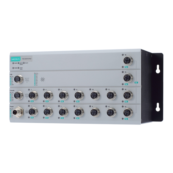
Page 4: Panel Layouts
Panel Layouts 1. PWR1 LED: for power input 1 2. MSTR/HEAD LED: for ring master or chain head 3. FAULT LED 4. 10/100/1000BaseT(X) port (M12 X-coded 8-pin female connector) 5. 10/100/1000BaseT(X) port LED 6. 10G BaseT(X) port LED 7. 10G BaseT(X) port (M12 X-coded 8-pin female connector) 8. -
Page 5: Mounting Dimensions (Unit = Mm)
Mounting Dimensions (unit = mm) Panel/Wall Mounting STEP 1: Mounting the TN-G4500 to a wall requires 4 screws. Use the ToughNet switch as a guide to mark the correct positions of the 4 screws. STEP 2: Use the 4 screws in the panel mounting kit. -
Page 6: Wiring Requirements
NOTE Before tightening the screws into the wall, make sure the screw head and shaft size are suitable by inserting the screw through one of the keyhole-shaped apertures of the ToughNet switch. STEP 3: Once the screws are fixed in the wall, hang the ToughNet switch on the 4 screws through the large opening of the keyhole- shaped apertures, and then slide the switch downwards. -
Page 7: Connecting The Power Supplies
Please read and follow these guidelines: • Use separate paths to route wiring for power and devices. If power wiring and device wiring paths must cross, make sure the wires are perpendicular at the intersection point. NOTE: Do not run signal or communications wiring and power wiring through the same wire conduit. -
Page 8: Connecting The Data Lines
Pinouts for the power input port V1– V2– Description Usage Connect “PWR1 Live / DC +” to the positive (+) PWR1 / DC + terminal when using a DC power source. Connect “PWR1 Neutral / DC –” to the negative PWR1 / DC –... - Page 9 Pinouts for the M12 (8-pin) Port M12 (8-pin, M) to M12 (8-pin, M) Cross-Over Cable Wiring M12 (8-pin, M) to M12 (8-pin, M) Straight-Trough Cable Wiring - 9 -...
-
Page 10: Led Indicators
M12 (8-pin, M) to RJ45 (8-pin) Cross-Over Cable Wiring M12 (8-pin, M) to RJ45 (8-pin) Straight-Trough Cable Wiring LED Indicators Several LED indicators are located on the ToughNet switch’s front panel. The function of each LED is described in the table below. Color State Description... - Page 11 Color State Description event is not triggered, or when the corresponding PORT alarm is disabled. When the TN switch is either the Master of this Turbo Ring, or the Head of this Turbo Chain. When the TN switch is Ring Master of this Turbo Ring and the Turbo Ring is MSTR/ GREEN...
Need help?
Do you have a question about the TN-G4516-8GPoE-4XGPoE-WV-T and is the answer not in the manual?
Questions and answers