Table of Contents
Advertisement
Quick Links
A
I
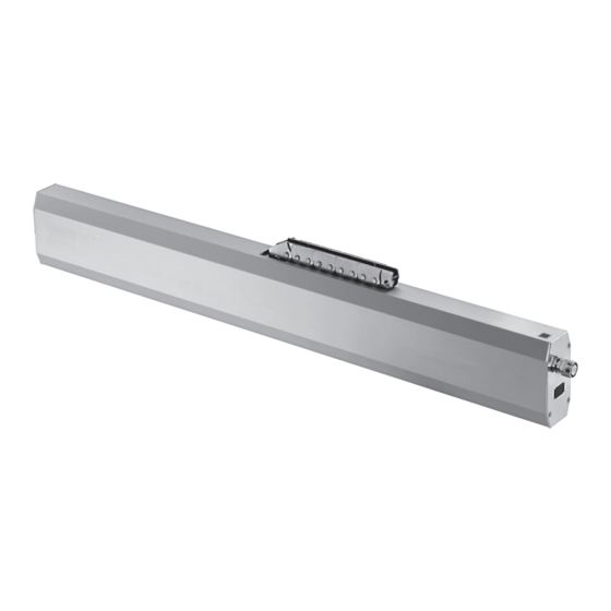
Ks15
ssembly
nstructIon
C
D
hain
rive for winDows
according to Machinery Directive
2006 / 42 / EG (annex VI)
Note the detailed assembly instructions!
Links to safety instructions, detailed assembly
eN
instructions, and manufacturer statements:
Please scan in the QR code and follow the link to
the A
homepage.
umüller
Ausführliche Montageanleitung beachten!
Links zu Sicherheitshinweisen, ausführlichen Montage-
De
Anweisungen und Hersteller-Erklärungen:
Bitte QR-Code einlesen und Link zur A
-
umüller
Homepage verfolgen.
Respectez les instructions de montage détaillées !
Liens vers les consignes de sécurité, détaillée instruc-
Fr
tions de montage et les explications du fabricant:
Veuillez scanner le code QR et suivre le lien vers la
page d'accueil de A
.
umüller
请遵守安全说明!
CN
关于装配说明的链接 (详细的) 和制造商声明
请读取 QR 码并跟踪 A
主页的链接。
umüller
Соблюдайте подробную инструкцию по
сборке!
Сылки на инструкции по монтажу и
ru
декларации производителя: Пожалуйста,
считайте QR-код и перейдите по ссылке на
главную страницу A
.
umüller
Przestrzegać szczegółowej instrukcji
montażu!
Link do szczegółowy instrukcji montażu i
Pl
uruchomienia:
Proszę zeskanować kod QR i otworzyć stronę
A
.
umüller
Montage-instructies in acht nemen!
Links naar veiligheidsinstructies, gedetailleerd
Nl
montage-instructies en fabrikantenverklaringen:
Gelieve QR-code in te lezen en link naar de
A
-homepage te volgen.
umüller
www.aumueller-gmbh.de
AUMÜLLER AUMATIC GMBH
Tel. +49 8271 8185-0
Gemeindewald 11
Fax +49 8271 8185-250
86672 Thierhaupten
info@aumueller-gmbh.de
9000033011_V0.1_KW32/21
KS15 24 V DC
1
KS15 230 V AC
1
2
F 54 +
F 54 +
FAB
K 153
K 154
min. FAB [mm]
800
875
875
Stroke
[mm]
1000
1000
1000
Total weight casement - including snow load -
is ≤ max. 220 kg
K154 (F54 included) - Part.-No. 524085 - Raico FRAME+100/120 RI
145
80
Ø5,5
10
Symbol:
10
Center of the window
F54
K154
The assembly of the F54
takes place during
the drive assembly.
K153 (F54 included) - Part.-No. 524080 - Schüco AWS 57 RO
145
80
Ø5,5
10
Symbol:
10
Center of the window
F54
The assembly of the F54
takes place during
the drive assembly.
KS15 24 V DC
2
KS15 230 V AC
1
F 54 + K 154
10
110
80
6
F 54
KS15
To increase the profile statics,
equip the window with
on-site facade
K 154
additional stiffening elements.
K154
Ø6,5x14,5
Ø8
Ø6,5x11,5
Ø5,5 (2x)
Ø10 (t=6)
Ø5,5
K153
Ø6,5x10,5
KS15 24 V DC
3
KS15 230 V AC
1
F 54 + K 154
K154
F54
KS15
K 154
56
60
21,5
21,5
A
40
40
16
25 10
1/2 FAB
25
80
25
C
C
B
Stroke
A
B
C
800
800
773
321,5
1000
920
893
381,5
m5
m5
m5
25 16
waistband of
chain-adapter
K154
m6
serves as a stop
m5
m5
K154
F54
K154
KS15
K154
K154
90°
m4
KS15
max. 4 Nm
KS15 24 V DC
4
KS15 230 V AC
2
F 54 + K 153
F54
K153
49
~ 61
To increase the pro-
file statics, equip the
window with additional
KS15
stiffening elements.
B
80
25
25
C
C
25
16
1/2 FAB
21,5
A
21,5
Stroke
A
B
C
800
800
773
321,5
1000
920
893
381,5
m5
K153
waistband of
chain-adapter
25 16
m6
serves as a stop
m5
m5
F54
K153
KS15
K153
K15
m4
max. 4 Nm
K153
90°
KS15 24 V DC
5
KS15 230 V AC
Advertisement
Table of Contents

Related Manuals for Aumuller KS15


Summary of Contents for Aumuller KS15
- Page 1 90° 86672 Thierhaupten info@aumueller-gmbh.de the drive assembly. KS15 9000033011_V0.1_KW32/21 max. 4 Nm KS15 24 V DC KS15 24 V DC KS15 24 V DC KS15 24 V DC KS15 24 V DC KS15 230 V AC KS15 230 V AC...
- Page 2 Risk of damage! programming with UniPC USB interface! external voltage! Risk of damage! programming with UniPC USB interface! 9000033011_V0.1_KW32/21 KS15 24 V DC KS15 24 V DC KS15 24 V DC KS15 24 V DC KS15 24 V DC...
- Page 3 Assembly and Commissioning Instructions according to Machinery Directive 2006 / 42 / EC (annex VI) KS15 S12 24V DC / KS15 S12 230V AC - C hAin riVe for winDowS...
- Page 4 Target Groups Warning and Safety Symbols Intended Use 3 - 8 Safety Instructions Data sheet KS15 S12 24V Data sheet KS15 S12 230V Explanations on the product label 9 - 11 Areas of application and Casement sizes Inspection before the installation...
- Page 5 reliminary emark bbreViAtionS Arning AnD SAfety SymbolS in theSe StruCtionS Index of abbreviations The symbols used in the instructions shall be strictly observed and have These abbreviations are used consistently throughout these assembly the following meaning: & operating instructions. Unless stated differently, all dimensions indi- cated in this document are in mm.
- Page 6 reliminary emark ntenDeD uSe Area of application / Scope of application This drive is intended for the electromotive opening and We as manufacturers are well aware of our duties and closing of windows in facade and roof areas. responsibilities regarding the development, manufactu- The main task of this product, in combination with ring and placing of safe window drives on the market and a window and a suitable external control unit, is to...
- Page 7 reliminary emark Hazard analysis according to DIN EN 60335-2-103 NRWG according to NRWG according to EN12101-2 with EN12101-2 without Use of the drive dual purpose for ventilation dual purpose for ventilation (1.Z.109) AUtion Natural ventilation Keep people away during closing! Installation height of drive and lower edge of casement: >...
-
Page 8: Safety Instructions
afety nstruCtions Afety inStruCtionS It is important to follow these instruc- Installation tions for the safety of persons. These These instructions address expert and safety-conscious Arning instructions shall be kept in a safe place electricians and / or qualifi ed personnel knowledgeable in for the entire service life of the products. - Page 9 afety nstruCtions Crush and shear points All-pole disconnecting devices shall be instal- To avoid injuries, crushing and shear points between led in the permanent electrical installation or casement and frame must be secured against entrapment external Control Unit for the drive. up to an installation height of 2,5 meters above the The mains supply lines 230 V / 400 V AC shall fl oor with appropriate measures.
-
Page 10: Ambient Conditions
afety nstruCtions Commissioning, operation and maintenance Replacement parts, fasteners and controls After the installation and after each modifi cation in the set The drive shall only be operated with control devices from up all functions shall be checked with a trial run. It shall the same manufacturer. -
Page 11: Data Sheet
1000 KS15 1000 S12 24V E6/C-0 525400 Set: Frame bracket and casement bracket (kit) Set: Frame bracket unit KS15 Schüco AWS 57 RO K153: Stainless steel, vibratory grinding 524080 F54: Aluminium, E6/C-0 Set: Frame bracket unit KS15 Raico FRAME+100/120 RI... - Page 12 Drives 1000 KS15 1000 S12 230V E6/C-0 495170 Set: Frame bracket and casement bracket (kit) Set: Frame bracket unit KS15 Schüco AWS 57 RO K153: Stainless steel, vibratory grinding 524080 F54: Aluminium, E6/C-0 524085 Set: Frame bracket unit KS15 Raico FRAME+100/120 RI...
- Page 13 heet OPTIONS Special model PU / pcs. Part.-No. Drive housing painted/powder coated in other RAL colours Lump sum for coating 516030 1 – 20 516004 516004 21 – 50 Specify at order stage: 51 – 100 516004 from 101 516004 Plug solution: -Click plug solution - 5 m –...
-
Page 14: Roof Window
FAB min. = L + 100 mm FAB > 1,80 meter = 2 drives KS15 800 mm stroke ≤ max. 220 kg KS15 1000 mm stroke ≤ max. 220 kg top-hung casement bottom-hung casement top-hung casement bottom-hung casement Snow load on roof windows for RWA-systems To increase the profile statics, equip the window with additional stiffening elements. -
Page 15: I Nstallation Step
reParing ssembly 1: i nstallatIon step nSpeCtion before the inStAllAtion Important instructions for a safe instal- Inspection of the intended use lation. Observe all instructions, wrong The planned use of the drive must be checked for com- Arning installation may result in serious injury! pliance with its intended use. -
Page 16: Scope Of Delivery
Prior to assembly, check items quantity in the delivery for Screws for plastic completeness. i.e. DIN 95606, DIN 95607, ISO 7049, ISO 7085, DIN 7500 round head with cross, external hex head, Accessories: chain drive KS15 Torx Assembly and Commissioning Instructions Tools required 1x german 1x english •... - Page 17 rame raCkets anD asement raCket 3: f nstallatIon step rAme brACKetS AnD ASement brACKet chüco aIco Frame brackets (different frame brackets for Schüco and Raico) Frame bracket (Set: Schüco) Frame bracket (Set: Raico) Frame bracket K153 (for Schüco) Frame bracket K154 (for Raico) ...
-
Page 18: Application Examples
Outward opening roof window - frame mounting - Schüco AWS 57RO F 54 on-site roof connection reference edge K153 Ks15 To increase the profile statics, equip the window with additi- onal stiffening elements. ~ 61 Outward opening roof window - frame mounting -... - Page 19 ( 800 stroke) ( 800 stroke) 381,5 (1000 Hub) 381,5 (1000 Hub) (1000 stroke) (1000 stroke) Ks15 723 (800 Hub) / 843 (1000 Hub) ( 800 stroke) (1000 stroke) 800 (800 Hub) / 920 (1000 Hub) 21,5 ( 800 stroke)
- Page 20 Screws - for mounting on the window - are to be provided by the customer! Make sure it is parallel to casement edge. Hole layout - frame bracket Kxxx Ks15 (bei Hub 800) ( 800 stroke) (bei Hub 1000) (1000 stroke)
- Page 21 SSembly CASement brACKetS AnD the DriVe „ Determine fastenings for casement brackets F54 „ Connect control voltage of the drive KS15 (e.g. using a „ Produce drill holes with appropriate cross-section. tester). „ Move out the chain of drive KS15 approx. 100 to Screws - for mounting on the window - are to 150 mm.
- Page 22 Able routing Note the softlauf modus! (see chapter: S oft run moDe „ Retract the chain of the drive KS15 so far, that the two Check swiveling area! (see chapter: mounting bolts are at the same height as the ...
-
Page 23: Cable Routing
7: C nstallatIon step Able routing Cable in the window frame Cable in glued cable duct Ks15 Ks15 Cable duct Glued cable duct Drill hole for cable Ø 9 in the window frame (in addition secured with countersunk screws against (cable bushing protects against damage to cable). -
Page 24: Electric Connection
24 V Dc 230 V ac Connection assignment 24 V 230 V KS15 KS15 No electrical No electrical connection possible connection possible OPEN CLOSE GN / YE = PE WH is used for communication, with... - Page 25 In multi-drive systems can be used, up to four individual drives and two locking drives. BU = blue Configuration is done by M-COM (See Assembly and Commissioning Instructions M-COM). WH = white polarity reversal FVUx 24 V KS15 KS15 24 V DC 24 V DC 24 V DC (SELV) M-COM FVUx 24 V...
- Page 26 Master / Slave 24 V Dc Individual Master Slave configuration FVUx 24 V KS15 KS15 24 V 24 V 24 V DC (SELV) polarity reversal FVUx 24 V No electrical No electrical connection possible connection possible is used for communication, with synchronized multi-drive operation.
- Page 27 leCtriC onneCtion M-COM (Main control unit) UniPC with configuration interface Order number: 524177 Order number: 524178 Application: Configuration module for the automatic Application: Hard- and software for configuration of configuration and monitoring of max. drives supplied by a umüller umatIc 4 opening drives / 2 locking drives GmbH type S12 / S3 in multi-drive systems.
- Page 28 leCtriC onneCtion afety heCk nstallatIon step nstallatIon step upply lineS of ontrol nit to the riVeS Afety CheCK AnD eSt run Observe current regulations and guidelines regarding Check the mounted system for its safety; perform test run the “Fire behavior of building materials-circuit integrity and commissioning.
- Page 29 aintenanCe anD ePair elp in CASe of AlfunCtionS epAirS AnD AintenAnCe AnD oDifiCAtion AintenAnCe Professional repair of a defect drive can only be performed at the To ensure continuous function and safety of the drive periodic mainte- manufacturer’s factory or manufacturer-certifi ed specialist company. nance by a specialist company is required at least once a year (as man- Unauthorized opening or manipulation of the drive terminates warranty.
- Page 30 isPosal arranty emounting ArrAnty AnD uStomer erViCe The drives are demounted by reversing the steps, as for the installation. In principal apply our: The adjustments are omitted. „General Terms for the Supply of Products and Services of the 1. Completely disconnect the system from the power supply before German Electrical Industry (ZVEI)“.
- Page 31 ertifiCAte AnD eClArAtion of onformity The proof of the application of a quality management We declare under our sole responsibility that the product system is for company: described under "Data sheet" is in conformity with the GmbH umüller umatIc following directives: according to the certifi cation basis DIN EN 9001 as well the "Declaration of Incorporation and Conformity"...
- Page 32 9000033001_V1.0_KW28/22...
Need help?
Do you have a question about the KS15 and is the answer not in the manual?
Questions and answers