Table of Contents
Advertisement
Quick Links
Assembly Instructions
according to Machinery Directive 2006/42/EC (annex VI)
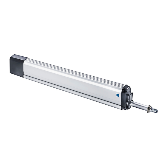
SP
24 V DC / 230 V AC
Spindle Drive
Aumüller Aumatic GmbH
Aumüller Aumatic GmbH
Gemeindewald 11
Gemeindewald 11
86672 Thierhaupten, Germany
86672 Thierhaupten, Germany
+49 (0)82 71 8185-0
+49 (0)82 71 8185-0
+49 (0)82 71 8185-250
+49 (0)82 71 8185-250
info@aumueller-gmbh.de
info@aumueller-gmbh.de
www.aumueller-gmbh.de
www.aumueller-gmbh.de
Advertisement
Table of Contents

Related Manuals for Aumuller SP Series


Summary of Contents for Aumuller SP Series
- Page 1 Assembly Instructions according to Machinery Directive 2006/42/EC (annex VI) 24 V DC / 230 V AC Spindle Drive Aumüller Aumatic GmbH Aumüller Aumatic GmbH Gemeindewald 11 Gemeindewald 11 86672 Thierhaupten, Germany 86672 Thierhaupten, Germany +49 (0)82 71 8185-0 +49 (0)82 71 8185-0 +49 (0)82 71 8185-250 +49 (0)82 71 8185-250 info@aumueller-gmbh.de...
- Page 2 This is a translation of the original assembly instructions into English Contact us during our business hours: Monday - Thursday 8 am to 4 pm and Friday 8 am - 12 am. Important note: We are aware of our responsibility, which is why we present life-supporting and value-preserving products with greatest possible con- scientiousness.
-
Page 3: Table Of Contents
Table of Contents Abbreviations / Warning notes, Risk Assessment / Duty to handover documentation ....4 / 5 / 6 Certificate / Declaration of Incorporation .....................7 / 8 Area of Application / Intended Use ........................9 Suitable applications for roof windows and vertical mounting windows (in façade area)......10 Pre-assembly Checks............................ - Page 4 Abbreviations / Warning notes Abbreviations: = casement bracket = bracket FÜ = casement overlap = drive / actuator = casement = frame FAB = overall width of casement FAH = overall height of casement = connecting cable / drive cable = Eye bolt = Collar screw G1/8 = Clamping blocks (thick, thin)
-
Page 5: Abbreviations / Warning Notes, Risk Assessment / Duty To Handover Documentation
Risk Assessment / Duty to handover documentation Risk Assessment Start for power-operated windows (machines) according to ISO 12100 Specification of use, General Approach operation and purpose of the window For information Identification Once the system planner has carried out the necessary risk assess- of dangers ment for power-operated windows and incorporated any specific Risk analysis... - Page 6 Safety instructions Read prior to installation and keep over the lifetime of the drive! Symbols for safety instructions Risk of crushing and entrapment ! Window closes automatically ! Caution / Warning During closing and opening the drive is stopped either by the Danger from electric current.
- Page 7 Certificate Assembly Instructions • Spindle Drive SP -24 V / 230 V 9000002601.doc Page...
-
Page 8: Certificate / Declaration Of Incorporation
Declaration of Incorporation Assembly Instructions • Spindle Drive SP -24 V / 230 V Page 9000002601.doc... -
Page 9: Area Of Application / Intended Use
Intended Use Area of Application / Range of Application Shown with the following General Use example Area of application For electromotive opening and closing of building openings in facades and roof areas. Examples are:bottom-hung, top- hung, side-hung, vertically pivoting and horizontally pivoting casements as well as light domes, flaps and blinds made of Example: roof area window base materials such as aluminium, plastic or wood. -
Page 10: Suitable Applications For Roof Windows And Vertical Mounting Windows (In Façade Area)
Suitable applications for windows in roofs and for facade window systems Roof window systems Explanation of symbols Pyramid Light dome Top hung Bottom hung highly recommended less recommended critical application Single direct (HSK) Single direct (HSK) Single direct (HSK) Single direct (HSK) General range of casement dimensions For the different drive contact points on the casement the following must be considered: Single contact directly on HSK... -
Page 11: Pre-Assembly Checks
Pre-assembly Checks Important instructions for safe assembly! Fully observe all WARNING instructions! Incorrect assembly may lead to serious injuries! Checking Installation Requirements Storage of the drives on site prior to the assembly Depending on the place of installation / type of window and Protective measures against damage, dust, humidity or on the real structural conditions there are different installa- contamination (for example caused by covers, film or card-... -
Page 12: Spindle Drive Sp 8 Xxx 24 V Dc (Detail Drawing / Overview / Technical Data)
Spindle drive SP 8 xxx in 24 V DC Detail drawing / Overview / Technical Data Dimension Sheet SP 8 xxx / SP 8-Z xxx 24 V DC s + 190mm Ø Ø 1/3 KLB 2/3 KLB +/- 8,0 Eye bolt for fixing Stroke „s“... -
Page 13: Spindle Drive Sp 8-Z Xxx 230 V Ac (Detail Drawing / Overview / Technical Data)
Spindle drive SP 8-Z xxx in 230 V AC Detail drawing / Overview / Technical Data Dimension Sheet SP 8-Z xxx in 230 V AC s + 190mm = min. 490 ( s = 300mm ) Ø Ø 1/3 KLB 2/3 KLB +/- 8,0 Eye bolt for fixing... -
Page 14: General Product Information Force-Path Diagram
General product information Force-path diagram Version Stroke (mm) (mm) Note max. load in N for extended spindle if unit suspended at rear! 24 V DC SP 8 - xxx L = (s +190) ength 2/3 KLB 1/3 KLB optional Rear suspension Front suspension Version Stroke... -
Page 15: Fitting Requirements
Assembly Requirements When installing the „partly incomplete machine„ Spindle drive type: SP 8 xxx in 24 V DC SP 8-Z xxx in 230 V DC the following requirements must be met in order to allow Tools required correct assembly with other components to produce a Depending on the application different tools will complete machine without compromising health and safety be needed to fasten the drives and brackets... -
Page 16: Casement Brackets (General Purpose And For Specific Profile Systems)
casement brackets & All-purpose Casement brackets for profile-specific system Ø6 F 1 casement bracket F 2 casement bracket with locking bolt Ø 6 mm extruded aluminium, Max load. 1000 N for Eternit roof lights ord.no. 150102 Max load. 800 N ord.no. -
Page 17: Mounting Brackets With Thick Clamping Blocks
Mounting brackets with thick clamping blocks Ø12 ( 14) Ø G1/8 „BS“ collar screw G 1/8 spare part for varios brackets with Ø 12,5 mm borehole Collar Ø 12 mm - ord.no. 172800 „KS“ clamping block SP-thick aluminum, for mounting brackets K5, K7 Ø... -
Page 18: Mounting Brackets With Thin Clamping Blocks
Mounting brackets with thin clamping blocks Ø12 ( 14) Ø G1/8 „BS“ collar screw G 1/8 spare part for varios brackets with Ø 12,5 mm borehole Collar Ø 12 mm - ord.no. 172800 „KS“ clamping block SP-thin aluminum, for mounting brackets K82, K4-long Ø... -
Page 19: Mounting Brackets With Clamping Bolt Connection
Mounting brackets with clamping bolt connection Ø 6,5 (x4) „KVS“ Clamping bolts Ø 6,5 2 pcs. for various brackets with Ø 20 mm hole ord.no. 155010 K 9 mounting bracket aluminium E6/C-0 - for mounting with various brackets ord.no. 158501 Ø20 Ø20 R15,5... -
Page 20: Recommended Fixings And Fasteners
Recommended fixings and Fasteners The selection of appropriate fasteners is an important prerequisite for the safe and proper CAUTION operation of drives on power-operated windows. Only use specified fasteners! Check before start of assembly which fasteners of size 6 can be used! All clamping and mounting screws shall be checked for tight fit and must be re-tightened, if necessary. - Page 21 General installation advices Positioning and fixation of brackets tighten with 2,0 - 2,5 Nm torque Fixation of brackets in guide of sliding link with Fixation of brackets in guide of sliding link with clamping screws collar screws and clamping blocks - insert clamping blocks on both sides of drive and tight.
-
Page 22: General Installation Advices
General installation advices Adjustment possibilities End switch Locknut M8-low SW13 Do not seal openings in housing Adjustment possibility for disconnection - openings may not be sealed with any materials whatsoever - loosen lock nut - manually turn AS inward and / or outward (dependent on assembly) - do not insert objects such as wire, screw drivers, etc. -
Page 23: Planning
Planning for outward opening windows in roof & facade area F... K... Mounting example Activation directly on HSK, bracket on the bar For drives acting directly on the leading edge (HSK), the opening angle depends on the distance between the hinge (pivot axis) and the actuation point of the drive and its stroke length, plus the opening width at the actuation point. - Page 24 Planning for outward opening windows in roof & facade area Facade window Facade window e.g. top hung or horizontally pivot. casem. e.g. top hung projecting casement F10.6 base plate set on site outward opening on HSK outward opening on HSK Roof casement system: Roof casement system: FAKRO SCHÜCO AWS 57RO...
-
Page 25: Assembly Procedure For Outward Opening Windows In Roof & Facade Area
Assembly procedure for outward-opening windows in roof & facade area SP 8 / SP 8-x possibly project drawing FG= ? 1x F... F10.6 e.g. F1 1x K... with parts for clamping 2x KS-thick 2 x BS Example calculation Check window size on site 2x KS-thin 2 x BS - Measure FAB and FAH,... - Page 26 Assembly procedure for outward-opening windows in roof & facade area ° Screw on mounting bracket e.g. - borehole intervals determined on site (Dimensions for brackets see page 17 - 19) - make sure it is parallel to the edge of the window gap to small Aluminium profile...
- Page 27 Assembly procedure for outward-opening windows in roof & facade area Suspend the drive in casem. bracket - insert pin - the pin needs to slot in securely (Clicking sound coming) Connect drive with casement bracket - adjust eyebolt if necessary (see page 22) - adjust contact pressure of casement by regulating the eyebolt and by sliding the drive in the bracket - make sure that the drive shut off via end switch (see page 22)
-
Page 28: Consideration Of The Safety And Trial Operation
Consideration of the safety and operational test 24V DC 230V AC Activation Activation element element OPEN OPEN CLOSE CLOSE Check safety of assembled system Check safety of assembled system - Connect control voltage - Connect control voltage - Check fasteners (brackets, mounting brackets) and - Check fasteners (brackets, mounting brackets) and tighten as necessary tighten as necessary... -
Page 29: Electrical Connection
Electrical connections Carry out the electrical connection according to the drive variant. Note: The direction of travel of the drive may be changed by interchanging (polarity reversal) the wires „BN – (brown) “ - „BU – (blue)“ . 24 V DC Version: without Z (close) contact Version: with Z (close) -
Page 30: Additional Remarks Regarding Cable Wiring And Cable Size Calculation
Additional remarks regarding cable wiring and cable size calculation Possibilities for connection of drive cable mm² Calculation formula in flush-mounted junction box for cable size required for a motor line (Total) (Length of motor line) mm² (Maximum voltage drop) *mm²) Example calculation Available figures: Drive current for each drive (2 x 0.8 A) from data sheet... -
Page 31: Operating Instructions
Operating Instructions Maintenance and Service / Cleaning Target group Maintenance and Service / Cleaning In order to ensure troublefree operation the following opera- This operating instructions is intended for operators tions shall be carried out every 1000 opening cycles, however instructed in Natural Smoke Exhaust system (NSE / SHEV) at least once a year according to DIN18232 / VdS- guidelines and natural ventilation of the window with knowledge of... -
Page 32: Troubleshooting
Troubleshooting Removal and disposal Removal and disposal Troubleshooting, Service and Repair To remove the drives reverse the sequence used for the Proper repair of a defective drive cannot be performed by assembly. Adjustment work is not required. the contractor or end-user and is therefore not permissible. Repairs can only be carried out by the manufacturer or by a specialist company authorized by the manufacturer. -
Page 33: Mechanical And Electrical Safety
Mechanical and Electrical Safety Avoiding risk situations Mounting and fastening material Required or supplied fastening material shall be se- Wall lected and, if necessary, supplemented to suit the Make sure that the building’s structure and the corresponding strain. power-operated window can move freely and does not clash with any Crush and shear points fixed parts (e.g. -
Page 34: Warranty And After-Sales Service
Warranty and After-Sales Service Warranty and After-Sales Service Basically our „General Terms and Conditions of Goods and Services by the Electrical Industry” issued by the Central Association of the Electrical Engineering and Electronics Industry (ZVEI) are applicable. This warranty complies with legal requirements and applies to the country in which the drive was purchased. - Page 35 Notes Assembly Instructions • Spindle Drive SP -24 V / 230 V 9000002601.doc Page...
- Page 36 Engineering Systemtechnik Service Rauch- und Kontrollierte, Parkraum- Wärmeabzug natürliche Lüftung Management...
Need help?
Do you have a question about the SP Series and is the answer not in the manual?
Questions and answers