
Related Manuals for Aumuller PLS S12 24V DC


Summary of Contents for Aumuller PLS S12 24V DC
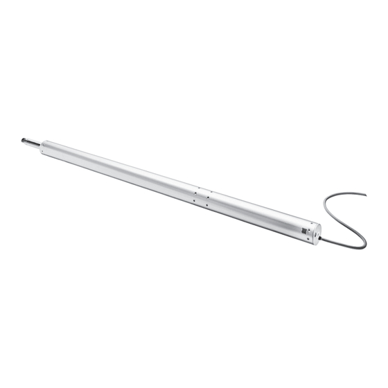
- Page 1 Assembly and Commissioning Instructions according to Machinery Directive 2006 / 42 / EC (annex VI) PLS S12 24V DC S PINDLE RIVE FOR WINDOWS...
- Page 2 ONTENTS Abbreviations Target Groups Warning and Safety Symbols Intended Use 3 - 8 Safety Instructions Data sheet PLS15 S12 24V DC Data sheet PLS30 S12 24V DC Data sheet PLS50 S12 24V DC Explanations on the product label 9 - 14 Areas of Application and Casement Sizes Opening angle at direct operation 15 - 16...
-
Page 3: Target Group
RELIMINARY REMARK BBREVIATIONS ARNING AND SAFETY SYMBOLS IN THESE Index of abbreviations STRUCTIONS These abbreviations are used consistently throughout these assembly The symbols used in the instructions shall be strictly observed and have & operating instructions. Unless stated differently, all dimensions indi- the following meaning: cated in this document are in mm. -
Page 4: Preliminary Remark
RELIMINARY REMARK NTENDED USE Area of application / Scope of application This drive is intended for the electromotive opening and We as manufacturers are well aware of our duties and closing of windows in facade and roof areas. responsibilities regarding the development, manufactu- The main task of this product, in combination with ring and placing of safe window drives on the market and a window and a suitable external control unit, is to... - Page 5 RELIMINARY REMARK Hazard analysis according to DIN EN 60335-2-103 NSHEV according to NSHEV according to EN12101-2 with EN12101-2 without Use of the drive dual purpose for ventilation dual purpose for ventilation (1.Z.109) AUTION Natural ventilation Keep people away during closing! Installation height of drive and lower edge of casement: >...
-
Page 6: Safety Instructions
AFETY INSTRUCTIONS AFETY INSTRUCTIONS It is important to follow these instruc- Installation tions for the safety of persons. These These instructions address expert and safety-conscious ARNING instructions shall be kept in a safe place electricians and / or qualifi ed personnel knowledgeable in for the entire service life of the products. - Page 7 AFETY INSTRUCTIONS Crush and shear points All-pole disconnecting devices shall be instal- To avoid injuries, crushing and shear points between led in the permanent electrical installation or casement and frame must be secured against entrapment external Control Unit for the drive. up to an installation height of 2,5 meters above the The mains supply lines 230 V / 400 V AC shall fl oor with appropriate measures.
-
Page 8: Ambient Conditions
AFETY INSTRUCTIONS Commissioning, operation and maintenance Replacement parts, fasteners and controls After the installation and after each modifi cation in the set The drive shall only be operated with control devices from up all functions shall be checked with a trial run. It shall the same manufacturer. -
Page 9: Data Sheet
ATA SHEET PLS15 S12 24V DC ATA SHEET Application: natural ventilation, SHEV, ferralux®-NSHEV Internal Intelligent Control Electronics S12 Options Programmable synchronised run (max. 4 drives) and special functions M-COM for automatic synchronised run of multi drive systems and automatic sequence control with FV locking drives (S3 / S12) Spindle tube end with interior thread for clevis Eyebolt and clevis for rear suspention... -
Page 10: Order Data
ATA SHEET ORDER DATA s [mm] L [mm] Version Finish PU / pcs. Part.-No. PLS15 300 S12 E6/C-0 576830 PLS15 400 S12 E6/C-0 576840 PLS15 500 S12 E6/C-0 576850 1065 PLS15 600 S12 E6/C-0 576860 1215 PLS15 750 S12 E6/C-0 576875 1000 1465... - Page 11 ATA SHEET PLS30 S12 24V DC ATA SHEET Application: natural ventilation, SHEV, ferralux®-NSHEV Internal Intelligent Control Electronics S12 Options Programmable synchronised run (max. 4 drives) and special functions M-COM for automatic synchronised run of multi drive systems and automatic sequence control with FV locking drives (S3 / S12) Spindle tube end with interior thread for clevis Eyebolt and clevis for rear suspention...
- Page 12 ATA SHEET ORDER DATA s [mm] L [mm] Version Finish PU / pcs. Part.-No. PLS30 300 S12 E6/C-0 577530 PLS30 400 S12 E6/C-0 577540 PLS30 500 S12 E6/C-0 577550 1065 PLS30 600 S12 E6/C-0 577560 1215 PLS30 750 S12 E6/C-0 577575 1000 1465...
- Page 13 ATA SHEET PLS50 S12 24V DC ATA SHEET Application: natural ventilation, SHEV, ferralux®-NSHEV Internal Intelligent Control Electronics S12 Options Programmable synchronised run (max. 4 drives) and special functions M-COM for automatic synchronised run of multi drive systems and automatic sequence control with FV locking drives (S3 / S12) Spindle tube end with interior thread for clevis Eyebolt and clevis for rear suspention...
- Page 14 ATA SHEET ORDER DATA s [mm] L [mm] Version Finish PU / pcs. Part.-No. PLS50 200 S12 E6/C-0 577620 PLS50 300 S12 E6/C-0 577630 1000 PLS50 400 S12 E6/C-0 577640 1100 PLS50 500 S12 E6/C-0 577650 1200 PLS50 600 S12 E6/C-0 577660 1350...
-
Page 15: Roof Window
REPARING ASSEMBLY REAS OF APPLICATION AND CASEMENT SIZES Areas of application and casement sizes: Roof window FAB max. = 1200 mm / solo FAH max. = 2500 mm Mounting of drives up to a casement size = 2500 mm / tandem of max. - Page 16 REPARING ASSEMBLY PENING ANGLE AT DIRECT OPERATION OUTWARD OPENING WINDOWS Application at the following activation Activation on HSK Activation on HSK Activation on NSK frame bracket on frame frame bracket on the transom frame bracket on the transom F10.8S F10.8S F10.8S K82-1 Kxxx...
-
Page 17: Installation Step
REPARING ASSEMBLY 1: I NSTALLATION STEP NSPECTION BEFORE THE INSTALLATION Important instructions for a safe instal- Inspection of the intended use lation. Observe all instructions, wrong The planned use of the drive must be checked for com- ARNING installation may result in serious injury! pliance with its intended use. -
Page 18: Installation Preparation
Phillips head or external hex head nach Maschinenrichtlinie 2006 / 42 / EG (Anhang VI) Instructions blind rivet nut Screws for plastic PLS S12 24V DC S PINDELANTRIEB FÜR ENSTER i.e. DIN 95606, DIN 95607, ISO 7049, ISO 7085, DIN 7500... - Page 19 ASEMENT BRACKETS NSTALLATION STEP ETERMINE THE CASEMENT BRACKETS Hole layout for casement brackets Casement bracket F10.8 S Casement bracket F10.10 Casement bracket F11ST / F11VA Ø8 Ø6,5 Ø10 Ø8 Ø6,5 Suspension with bore Ø 8 mm Suspension with bore Ø 8 mm Suspension with bore Ø...
- Page 20 RAME BRACKETS NSTALLATION STEP ETERMINE THE FRAME BRACKETS Hole layout for frame brackets Frame bracket K70 Frame bracket K82-1 Frame bracket K121 Ø6,5 Ø 7 Ø14,5 Ø6,5 SCHÜCO RS106D HEROAL 085D for swivelling suspension mounting with B6 for swivelling suspension mounting with B6 for swivelling suspension mounting with B6 Frame bracket K121-1 Frame bracket K127-1 Verstellbare Klemmbefestigung B6...
- Page 21 OLE LAYOUT CTIVATION ON NSTALLATION STEP OLE LAYOUT CTIVATION ON System: HEROAL 085D Roof window - outward opening - Frame assembly - HSK Top view - Drilling 130 mm cutaway 130 mm Ausfräsung F28-1 11,5 11,5 System: SCHÜCO AWS 70 Top-hung casement - outward opening - Top view - Drilling Frame ssembly - HSK...
- Page 22 OLE LAYOUT CTIVATION ON OLE LAYOUT CTIVATION ON System: HEROAL 085D Roof window - outward opening - Frame assembly - HSK Top view - Drilling 130 mm cutaway 130 mm Ausfräsung F28-1 K82-1 Top view Assembly Instruction Spindle Drive PLS...
- Page 23 OLE LAYOUT CTIVATION ON NSTALLATION STEP OLE LAYOUT CTIVATION ON System: HEROAL 085D Roof window - outward opening - Frame assembly - NSK Top view - Drilling 130 mm Ausfräsung 130 mm cutaway K121 System: SCHÜCO AWS 57RO Roof window - outward opening - Frame assembly - NSK Top view - Drilling K121-1 System: WICONA Wictec 50...
- Page 24 NSK / S OLE LAYOUT CTIVATION ON KY LIGHT OLE LAYOUT CTIVATION ON System: RAICO Wing 105D Roof window - outward opening - Frame assembly - NSK Top view - Drilling 21,5 21,5 Optional Optional: Angle 151322 Winkel 151322 K127-1 Top view NSTALLATION STEP KY LIGHT...
- Page 25 SSEMBLY FOR DIRECT OPERATION ACTIVATION ON SSEMBLY FOR DIRECT OPERATION ACTIVATION ON NSTALLATION STEP OUTWARD OPENING Fit casement bracket F10.8S . Determine fastenings. Produce drill holes with appropriate cross-section. Make sure it is parallel to casement edge. For the mounting dimensions please refer to the „Casement bracket“...
- Page 26 SSEMBLY FOR DIRECT OPERATION ACTIVATION ON Untighten the cylinder head screw M6 from the Equipment: Adjustable clamping B6 adjustable clamping B6 . To facilitate insertion of the drive in the adjust- 2x collar screw Ø 14, G1/8“ able clamping B6 , screw in a third screw M6 in the ...
- Page 27 SSEMBLY FOR SIDE CLOSING EDGE OPERATION ACTIVATION ON - NSK NSTALLATION STEP SSEMBLY FOR SIDE CLOSING EDGE OPERATION Fit casement bracket F11/ST / F11VA . Determine fastenings. Produce drill holes with appropriate cross-section. Make sure it is parallel to casement edge. For the mounting dimensions please refer to the „Casement bracket“...
- Page 28 SSEMBLY FOR SIDE CLOSING EDGE OPERATION AN DER Untighten the cylinder head screw M6 from the adjustable clamping B6 . To facilitate insertion of the drive in the adjust- K127-1 able clamping B6 , screw in a third screw M6 in the middle threaded hole.
- Page 29 SSEMBLY FOR SIDE CLOSING EDGE OPERATION ACTIVATION ON Adjust casement pressure. Tighten the cylinder Window must be fully closed. head screw M6 from the adjustable clamping B6 to torque of 10 Nm. To fi t the second drive. K127-1 F11ST F11 VA...
- Page 30 LECTRIC CONNECTION 6: E NSTALLATION STEP LECTRIC CONNETCTION Make sure when establishing the connection Direction Wire colour coding that there is no voltage at the terminals! of travel Unused wires must be safely insulated! Colour DIN IEC 757 OPEN black The running direction of the drive may be changed by interchanging (polarity reversal) the wires „BN –...
-
Page 31: Electric Connection
LECTRIC CONNECTION LECTRIC CONNETCTION Multi-drive operation with M-COM M-COM (Main control unit) Order number: 524177 Application: Confi guration module for the automatic confi guration and monitoring of max. 4 drive 1 drive 2 opening / 2 locking drives type S12 / S3 Connection in multi-drive systems. - Page 32 LECTRIC CONNECTION AFETY CHECK NSTALLATION STEP NSTALLATION STEP UPPLY LINES OF ONTROL NIT TO THE RIVES AFETY CHECK AND EST RUN Observe current regulations and guidelines e.g. DIN 4102- Check the mounted system for its safety; perform test run 12 regarding the “Fire behavior of building materials- and commissioning.
-
Page 33: Maintenance And Repair
AINTENANCE AND REPAIR ELP IN CASE OF ALFUNCTIONS EPAIRS AND AINTENANCE AND MODIFICATION To ensure continuous function and safety of the drive periodic maintenan- AINTENANCE ce by a specialist company is required at least once a year (as mandated Professional repair of a defect drive can only be performed at the by law for smoke and heat exhaust systems). -
Page 34: Disposal / Warranty
ISPOSAL ARRANTY EMOUNTING ARRANTY AND USTOMER ERVICE The drives are demounted by reversing the steps, as for the installation. In principal apply our: The adjustments are omitted. „General Terms for the Supply of Products and Services of the 1. Completely disconnect the system from the power supply before Electrical Industry (ZVEI)“. -
Page 35: Declaration Of Conformity
ERTIFICATE AND ECLARATION OF ONFORMITY The proof of the application of a quality management We declare under our sole responsibility that the product system is for company: described under "Data sheet" is in conformity with the GmbH UMÜLLER UMATIC following directives: according to the certifi cation basis DIN EN 9001 as well the "Declaration of Incorporation and Conformity"... - Page 36 AUMÜLLER AUMATIC GMBH AUMÜLLER AUMATIC GMBH Tel. +49 8271 8185-0 Tel. +49 8271 8185-0 Gemeindewald 11 Gemeindewald 11 Fax +49 8271 8185-250 Fax +49 8271 8185-250 86672 Thierhaupten 86672 Thierhaupten info@aumueller-gmbh.de info@aumueller-gmbh.de www.aumueller-gmbh.de 9000017000_V0.1_KW05/14 9000019001_V1.1_KW11/19...
Need help?
Do you have a question about the PLS S12 24V DC and is the answer not in the manual?
Questions and answers