Table of Contents
Advertisement
Quick Links
Advertisement
Table of Contents

Related Manuals for Advantech iDAQ-934


Summary of Contents for Advantech iDAQ-934
- Page 1 User Manual iDAQ Chassis (iDAQ-934 & iDAQ-964)
- Page 2 No part of this manual may be reproduced, copied, translated, or transmitted in any form or by any means without the prior written permission of Advantech Co., Ltd. The information provided in this manual is intended to be accurate and reliable.
- Page 3 This product has passed the CE test for environmental specifications when shielded cables are used for external wiring. We recommend the use of shielded cables. This type of cable is available from Advantech. Please contact your local supplier for ordering information.
- Page 4 Document Feedback To assist us with improving this manual, we welcome all comments and constructive criticism. Please send all feedback in writing to support@advantech.com. Packing List Before system installation, check that the items listed below are included and in good condition.
- Page 5 In accordance with IEC 704-1:1982 specifications, the sound pressure level at the operator’s position does not exceed 70 dB (A). DISCLAIMER: These instructions are provided according to IEC 704-1 standards. Advantech disclaims all responsibility for the accuracy of any statements contained herein. iDAQ-934_964 User Manual...
- Page 6 Safety Precautions - Static Electricity Follow these simple precautions to protect yourself from harm and the products from damage. To avoid electrical shock, always disconnect the power from the PC chassis before manual handling. Do not touch any components on the CPU card or other cards while the PC is powered on.
-
Page 7: Table Of Contents
Contents Chapter Start Using iDAQ Chassis....1 Overview ....................2 Product Overview..................2 Figure 1.1 Front View of iDAQ-934..........2 Figure 1.2 Front View of iDAQ-964..........3 Product Features..................4 1.3.1 Power Input................... 4 1.3.2 Upstream USB Port ..............4 1.3.3 Downstream USB Port.............. - Page 8 Analog Input.................... 16 3.3.1 Instant Analog Input Acquisition ..........16 Figure 3.4 Instant analog input acquisition ........ 16 3.3.2 Buffered Analog Input Acquisition..........17 Figure 3.5 Buffered analog input acquisition ......17 Figure 3.6 Start and stop of the analog input acquisition ..17 Figure 3.7 Start and stop of the analog input acquisition with delay 3.3.3 Analog Input Convert Clock Signal Behavior......
- Page 9 Figure 3.34Device description shown in Navigator..... 32 Appendix A Specifications ........35 Analog Input .................... 36 Analog Output ..................36 Digital Input ..................... 36 Digital Output ..................36 Counter ....................36 Programmable Function Pins (PFP) ............36 General ....................37 Function Block..................38 Appendix B System Dimensions ......39...
- Page 10 iDAQ-934_964 User Manual...
-
Page 11: Chapter 1 Start Using Idaq Chassis
Chapter Start Using iDAQ Chassis... -
Page 12: Overview
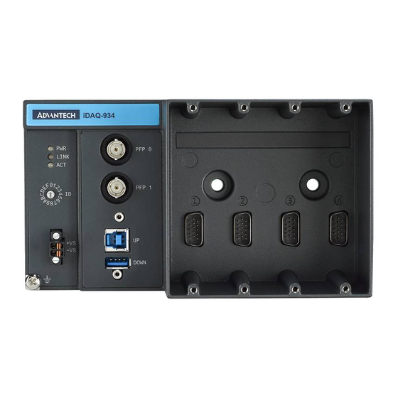
This chapter provides an overview of Advantech industrial data acquisition (iDAQ) chassis for iDAQ-934 and iDAQ-964, its features and accessories. iDAQ-934 is a four-slot data acquisition chassis with robust design for use with iDAQ modules. Various analog and digital I/O signals can be measured or output when using with the corresponding iDAQ modules. - Page 13 IDAQ-964 Figure 1.2 Front View of iDAQ-964 Number Component LED indicators Slots for iDAQ modules Programmable function pin (PFP) BNC connectors PCI Express interface iDAQ-934_964 User Manual...
-
Page 14: Product Features
Product Features 1.3.1 Power Input The iDAQ chassis requires an external power supply to operate. Connect the exter- nal power supply to the 2-pin spring terminal, and insert the terminal to the power input connector. Refer to 2.4.2 for the pin assignment of the terminal and A.7 for the required supply voltage and power rating. -
Page 15: Chassis Grounding Screw
XNavi installer, so that the iDAQ modules will be recognized by your system. The driver package can be found on the Advantech Support Portal (https:// www.advantech.com/support). Search for iDAQ on the support portal, then the corre- sponding driver/SDK package can be found. -
Page 16: Software Utilities
All these software packages are available on Advantech website: http://www.advantech.com/. The Advantech Navigator is a utility that allows you to set up, configure and test your device, and later stores your settings in a proprietary database. -
Page 17: Chapter 2 Installation Guide
Chapter Installation Guide... -
Page 18: Installation
Installation iDAQ-934 After the device drivers are installed, the iDAQ-934 chassis can be installed in the computer. Touch any metal surface of the computer to discharge any static electricity that may be in your body. Insert the USB cable into the designated USB port. -
Page 19: Mounting
Mounting The iDAQ-934 provides two types of mounting method. One is DIN-rail and the other is wall mount. 2.2.1 DIN rail mount The DIN Rail mounting kit is attached along with the package. Please make sure that the mounting kit is well-packed and components are completely included as follow: 2 x frames ... -
Page 20: Wall Mount
2.2.2 Wall mount There are two holes in the iDAQ-934 chassis module slot area. Those are the holes reserved for the wall mount. The following figures indicate the dimensions for mount- ing the iDAQ-934 chassis in a wall-mounting scenario. (unit: mm) Figure 2.3 Wall-mount dimensions (1) -
Page 21: Using Idaq Modules
Using iDAQ Modules Below are the steps to insert the iDAQ modules into the iDAQ chassis. Insert the module following the guide rail to the end. Screw the two screws tight onto the chassis, note that you should balance the depth of two screws when you screw them tightly. -
Page 22: Signal Connection And Pin Definition
Signal Connection and Pin Definition 2.4.1 Programmable Function Pin Connector The PFP stands for programmable function pin. It provides multiple functions such as clock I/O and trigger I/O. Refer to 3.1 and 3.6 for detailed application information, and also A6 for the signal specification. Figure 2.6 Pin assignment of PFP connector Pin Name Description... -
Page 23: Chapter 3 Function Details
Chapter Function Details Interface Introduction... -
Page 24: Function Details
Each slot on iDAQ-934 has its own acquisition engine, which means every slot can use different timing signals (start trigger, stop trigger, and sample clock) to perform independent acquisition tasks. -
Page 25: Start Trigger And Stop Trigger
3.2.2 Start Trigger and Stop Trigger Start trigger and stop trigger may come from one of the following sources: Software command (choose “None” in the software) One of the programmable function pin (PFP) inputs Trigger from one of the slots ... -
Page 26: Put
Figure 3.3 Signal routing for programmable function pin 1 as output. Analog Input Insert an iDAQ module supporting analog input function to perform analog input mea- surement. The following sections describe the analog input acquisition mechanism. For detailed specifications of the analog input functions, please refer to the document of the individual iDAQ module. -
Page 27: Buffered Analog Input Acquisition
3.3.2 Buffered Analog Input Acquisition With buffered analog input acquisition, the ADC conversion rate and the duration of the acquisition is controlled by hardware timing signals. All conversion results are sampled and stored in the buffer memory before sending back to the host computer as shown in Figure 3.5. -
Page 28: Analog Input Convert Clock Signal Behavior
The start and stop of acquisition can also be delayed in number of samples after receiving the corresponding trigger signal. As shown in Figure 3.7, the start of acqui- sition is delayed by 3 samples after receiving a start trigger, and the stop of acquisi- tion is delayed by 2 samples after receiving a stop trigger. - Page 29 When the sample clock rises, the multiplexed analog input module automatically gen- erates required convert clocks using the maximum allowable convert clock rate of the ADC for all enabled channels. The MUX routes one of the enabled channels for each convert clock in the order of channel number.
- Page 30 Simultaneously Sampled Analog Input Module In a simultaneously sampled analog input module, each analog input channel has its own ADC. When the sample clock rises, the ADC of all enabled channels start con- version simultaneously. The sampled results represent the analog input values at the same time.
- Page 31 Sigma-Delta ADC Analog Input Module Unlike the successive-approximation register (SAR) ADC, which performs one con- version for each convert clock, the sigma-delta ADC requires a continuous high-fre- quency oversample clock to perform the conversion. Therefore, this kind of modules cannot accept the sample clock from the programmable clock divider output of the chassis, programmable function pins, or signal of other slots as other types of analog input modules do.
- Page 32 Low Conversion Rate ADC Analog Input Module For iDAQ modules measuring slow varying signals such as temperature, strain, or pressure, the conversion rate of the ADC is usually accordingly slow. To prevent the sample rate from being limited to a low value due to this characteristic when synchro- nizing low conversion rate ADC analog input modules with other types of iDAQ mod- ules, the sample rate of the module and conversion rate of the ADC are independently set.
-
Page 33: Analog Comparison
3.3.4 Analog Comparison Some of the analog input modules provide analog comparison function. The compare result can be routed to the chassis as a timing signal. Analog comparison function compares one of the analog input signals to a preset threshold value. If the analog input signal is higher than the threshold value, result signal is high;... -
Page 34: Analog Output
Analog Output Insert an iDAQ module supporting analog output function to perform analog output update/generation. The following sections describe the analog output update/genera- tion mechanism. For detailed specifications of the functions, refer to the document of the corresponding iDAQ module. 3.4.1 Static Analog Output Update With static analog output update, the analog output voltage or current is updated only... - Page 35 The start and stop of the generation are controlled by the start trigger and stop trig- ger, respectively. When configuration is complete, the acquisition engine of the iDAQ chassis is at standby state. After receiving a start trigger, generation becomes active and each rising edge of the sample clock converts one analog output sample.
-
Page 36: Digital Input
Digital Input Insert an iDAQ module supporting digital input function to perform digital input mea- surement. The following sections describe the digital input acquisition mechanism. For detailed specifications of the functions, refer to the document of the correspond- ing iDAQ module. 3.5.1 Digital Input Functions Digital Input Interrupt... - Page 37 Digital Input Pattern Match Interrupt Digital input channels can also generate an interrupt by detecting a specific pattern. The pattern can be configured by ports, and each channel can be enabled or dis- abled the detection independently. For example, if channels 0, 1, 2, 3, 6, and 7 of a digital input port is pattern match detect enabled, and the pattern is “10xx0100”...
-
Page 38: Instant Digital Input Acquisition
3.5.2 Instant Digital Input Acquisition With instant digital input acquisition, the software controls the sample timing. Each time the software sends a “read instant digital input sample” command, the state of all digital input channels is sampled as shown in Figure 3.26. Figure 3.26 Instant digital input acquisition 3.5.3 Buffered Digital Input Acquisition... - Page 39 The start and stop of the acquisition are controlled by the start trigger and stop trig- ger, respectively. When configuration is completed, the acquisition engine of the iDAQ chassis is at standby state. After receiving a start trigger, acquisition becomes active and each rising edge of the sample clock acquires one analog input sample.
-
Page 40: Digital Output
Digital Output Insert an iDAQ module supporting digital output function to perform digital output update/generation. The following sections describe the digital output update/genera- tion mechanism. For detailed specifications of the functions, refer to the document of the corresponding iDAQ module. 3.6.1 Static Digital Output Update With static digital output update, the digital output state is updated only when the soft-... - Page 41 The start and stop of the generation are controlled by the start trigger and stop trig- ger, respectively. When configuration is completed, the acquisition engine of the iDAQ chassis is at standby state. After receiving a start trigger, generation becomes active and each rising edge of the sample clock converts one analog output sample.
-
Page 42: Status Indication
Status Indication The LED indicates the chassis status. Please refer to below table for the status indi- cation with respective color state. LED Color Green Yellow Power on No power Upstream is connected to Upstream is connected to Upstream is not con- LINK SuperSpeed (5 Gb/s) High-Speed (480 Mb/s) - Page 43 The rotary switch and the its corresponded number can be found in below table. Switch Position Chassis ID Switch Position Chassis ID iDAQ-934_964 User Manual...
- Page 44 iDAQ-934_964 User Manual...
-
Page 45: Appendix A Specifications
Appendix Specifications... -
Page 46: Analog Input
Analog Input Please refer to the specifications of individual iDAQ analog input module. Analog Output Please refer to the specifications of individual iDAQ analog output module. Digital Input Please refer to the specifications of individual iDAQ digital input module. Digital Output Please refer to the specifications of individual iDAQ digital output module. -
Page 47: General
General iDAQ-934: Interface: SuperSpeed USB 3.0 Data transfer rate: 5 Gbps max. USB downstream port: 1 port Power Input: 10 ~ 30 V Power Consumption: 24 W max., including modules and USB downstream port loads Power consumption from USB: 100 μA max. -
Page 48: Function Block
Function Block iDAQ-934 iDAQ-964 iDAQ-934_964 User Manual... -
Page 49: Appendix B System Dimensions
Appendix System Dimensions... -
Page 50: Chassis
Chassis iDAQ-934 iDAQ-934_964 User Manual... - Page 51 iDAQ-964 iDAQ-934_964 User Manual...
-
Page 52: Mounting
Mounting Wall Mount for iDAQ-934 iDAQ-934_964 User Manual... - Page 53 iDAQ-934_964 User Manual...
- Page 54 No part of this publication may be reproduced in any form or by any means, such as electronically, by photocopying, recording, or otherwise, without prior written permission of the publisher. All brand and product names are trademarks or registered trademarks of their respective companies. © Advantech Co., Ltd. 2021...
Need help?
Do you have a question about the iDAQ-934 and is the answer not in the manual?
Questions and answers