Advantech IPPC-6172A Series User Manual
17" sxga tft lcd core 2 quad / core 2 duo industrial panel pc with 2 x pci slots
Hide thumbs
Also See for IPPC-6172A Series:
- User manual (88 pages) ,
- User manual (74 pages) ,
- User manual (72 pages)

Related Manuals for Advantech IPPC-6172A Series


Summary of Contents for Advantech IPPC-6172A Series
- Page 1 User Manual IPPC-6172A Series 17" SXGA TFT LCD Core 2 Quad / Core 2 Duo Industrial Panel PC with 2 x PCI Slots...
- Page 2 Because of Advantech’s high quality-control standards and rigorous testing, most of our customers never need to use our repair service. If an Advantech product is defec- tive, it will be repaired or replaced at no charge during the warranty period. For out- of-warranty repairs, you will be billed according to the cost of replacement materials, service time and freight.
- Page 3 Technical Support and Assistance Visit the Advantech web site at www.advantech.com/support where you can find the latest information about the product. Contact your distributor, sales representative, or Advantech's customer service center for technical support if you need additional assistance.
- Page 4 Safety Instructions Read these safety instructions carefully. Keep this User Manual for later reference. Disconnect this equipment from any AC outlet before cleaning. Use a damp cloth. Do not use liquid or spray detergents for cleaning. For plug-in equipment, the power outlet socket must be located near the equip- ment and must be easily accessible.
-
Page 5: Table Of Contents
Contents Chapter General Information ......1 Introduction ....................2 Specifications .................... 3 1.2.1 General ..................3 1.2.2 Standard PC Functions..............3 1.2.3 Display ..................3 1.2.4 Audio Functions ................3 1.2.5 PCI bus Ethernet Interface............4 1.2.6 Touchscreen Specifications ............4 1.2.7 Environmental ................ - Page 6 BIOS Setup Program ................24 5.1.1 Legend Box................. 24 5.1.2 List Box ..................25 5.1.3 Sub-menu ................... 25 Main Setup....................25 Advanced BIOS Setup ................26 5.3.1 Super I/O Configuration .............. 29 5.3.2 ACPI Configuration ..............32 5.3.3 AHCI Configuration..............33 5.3.4 APM Configuration..............
-
Page 7: Chapter 1 General Information
Chapter General Information... -
Page 8: Introduction
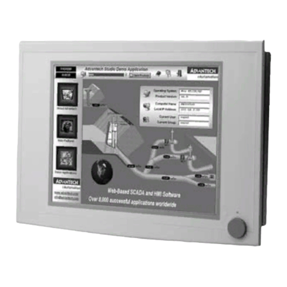
2.8GHz or Core 2 Duo up to 3.0GHz Friendly HMI Systems in the IPPC-6172A series are equipped with a 17" LCD screen, which pro- vides high resolution display quality. The result is vivid, bright, and sharp quality images. The panel PC is perfectly suited for Windows OS. The touschscreen version enables simple operation, making the Panel PC a solid industrial digital controller interface. -
Page 9: Specifications
Specifications 1.2.1 General Dimensions (W x H x D): Front Panel: 481.9 x 355.9 x 6 mm (18.97" x 14.01" x 0.24") Control Box: 362 x 285 x 112.2 mm (14.25" x 11.22" x 4.42") Cut out Dimensions: 454 x 338 mm (17.87' x 13.31") ... -
Page 10: Pci Bus Ethernet Interface
1.2.5 PCI bus Ethernet Interface Chipset: Intel 82567-LM Gigabit LAN (IAMT), Intel 82574L Gigabit LAN Ethernet Interface: 10/100/1000Base-T x 2 1.2.6 Touchscreen Specifications Type: Analog resistive 5-wire Lifespan: 36 million, writing rate is 250g at 2 times/s Light Transmission: >80% ... -
Page 11: Dimensions
Dimensions 285.00 [11.22] 285.00 [11.22] 143.90 [5.67] 143.90 [5.67] 8.72 [0.34] 8.72 [0.34] 355.87 [14.01] 355.87 [14.01] 266.70 [10.50] 266.70 [10.50] 40.30 [1.59] 40.30 [1.59] 335.97 [13.23] 335.97 [13.23] IPPC-6172A User Manual... - Page 12 IPPC-6172A User Manual...
-
Page 13: Chapter 2 System Setup
Chapter System Setup... -
Page 14: General
General Before you start the computer, please follow these procedures for set up: Check and adjust jumpers on the motherboard (see Chapter 3) Install DDR3 SDRAM Install a CPU Install add-on cards Connect the wires, cables and accessories Mount the computer Program the BIOS settings Install an operating system. -
Page 15: Usb Ports
2.1.4 USB Ports An external USB device may be connected to the system via the 4-pin USB ports located on the rear side of the system unit. Connect the external device to the system. The USB ports support hot plug-in connection. You should install the device driver before you use the device. -
Page 16: Installing A Cpu
Installing a CPU The CPU can be upgraded to improve system performance. The system provides Socket LGA775 architecture which supports Intel Core 2 Quad up to 2.8GHz and Intel Core 2 Duo up to 3.0GHz. Unlock the back cover and remove it. Remove the CPU cooler. - Page 17 IPPC-6172A User Manual...
-
Page 18: Installing A 2.5" Sata Hdd
Installing a 2.5" SATA HDD You can attach two enhanced Serial Advanced Technology Attachment (SATA) hard disk drives to IPPC-6172A's internal controller which uses PCI local bus interface. The following instructions are for installation: Unscrew the back cover and open it. Remove four screws and take off HDD bracket. - Page 19 Remove the PCI riser card by loosing the 2 screws which fix the card to the bracket. Then find the PCIe riser card from the accessory box and fix it to the bracket with 2 screws. Replace the back cover and fix it with 5 screws. This system supports two PCIe expansion cards.
-
Page 20: Mounting Instructions
Mounting Instructions There are two ways to mount the system: panel mounting or rack mounting. 2.6.1 Panel Mounting Take the four mounting brackets out of the accessory box. Attach the four mounting brackets by inserting the screws into the keyhole slots on the cover of the monitor. -
Page 21: Chapter 3 Jumper Settings & Connectors
Chapter Jumper Settings & Connectors... -
Page 22: Jumper Settings
Jumper Settings This section tells how to set the jumpers to configure your card. For the locations of each jumper, see the board layout diagram depicted earlier in this chapter. You con- figure your card to match the needs of your application by setting jumpers. A jumper is the simplest kind of electric switch. -
Page 23: Connectors
3.1.2 Connectors Onboard connectors link the panel PC to external devices such as hard disk drives or floppy drives. The table below lists the function of each of the board’s connectors. Table 3.2: Connectors CRT & COM4 D-Sub 15-PIN& D-Sub 9-PIN CN2&CN3 LVDS 24/48 BIT LVDS... -
Page 24: Com4 Settings (J20)
3.1.3 COM4 Settings (J20) This jumper is used to select RS232 (default) / RS422 / RS485 Table 3.3: COM4 Settings RS-232 RS-422 RS-485 RS-232 RS-422 RS-485 NDCD NDTR NDSR NRTS NCTS 3.1.4 Clear CMOS (CLRTC1) This jumper is used to erase CMOS data and reset system BIOS information. Follow the procedures below to clear the CMOS. -
Page 25: Chapter 4 Intel Chipset
Chapter Intel Chipset... -
Page 26: Overview
Overview In IPPC-6172A, Advantech provides a CD-ROM with utilities and drivers included. Please install the Chipset INF driver, VGA graphics driver, LAN driver, audio driver, Touch Screen driver sequentially. Utilities and Drivers The following utilities and drivers are provided with IPPC-6172A. You can also find out the updated description of the utilities and drivers in the ReadMe.txt file on the... -
Page 27: Dual Display Setting
Dual Display Setting If you use CRT monitor, you must Connections to CRT port in during system boot up. During system boot up, the system will set CRT parameter. If you have multiple devices, you can set them. Click Intel graphic icon from the toolbars Select Graphics properties This control allows selection of a device page. -
Page 28: Touchscreen Installation & Configuration
4.3.1 Touchscreen Installation & Configuration Driver Installation For driver installation, please insert the support CD and refer to the path: \\Touch- screen Driver\DMC 6000 (Combo)\Manual\PenMount Win2K&XP&2003&Vista Uni- versal Driver Manual V1.02.pdf IPPC-6172A User Manual... -
Page 29: Chapter 5 Ami Bios Setup
Chapter AMI BIOS Setup... -
Page 30: Bios Setup Program
BIOS Setup Program The main BIOS setup menu is the first screen that you can navigate. Each main BIOS setup menu option is described in this user's guide. The Main BIOS setup menu screen has two main frames. The left frame displays all the options that can be configured. -
Page 31: List Box
5.1.2 List Box This box appears only in the opening screen. The box displays an initial list of config- urable items in the menu you selected. 5.1.3 Sub-menu Note that a right pointer symbol (u) appears to the left of certain fields. This pointer indicates that you can display a sub-menu from this field. -
Page 32: Advanced Bios Setup
Advanced BIOS Setup Select the Advanced tab from the setup screen to enter the Advanced BIOS Setup screen. You can select any of the items in the left frame of the screen, such as Supe- rIO Configuration, to go to the sub menu for that item. You can display an Advanced BIOS Setup option by highlighting it using the <Arrow>... - Page 33 Intel (R) Virtualization Tech The choices of Intel Virtulization Technology are Disabled and Enabled. If you need to use virtulization technology and install a virtual machine, please select Enabled; if you just want to install a normal OS, please select Disabled. Execute-Disable Bit Capability The choices of Execute-Disable Bit Capability are Enabled, Disabled.
- Page 34 SATA#1 Configuration The choices of SATA configuration are Disabled, Compatible, and Enhanced. Configure SATA #1 as This item allows to configure SATA as IDE, RAID, or AHCI. Note! IPPC-6172A supports RAID 0 or 1 so RAID recovery function is not available in Intel Matrix Storage utility.
-
Page 35: Super I/O Configuration
Note! Different IDE disk drives take longer for the BIOS to locate than others do. 5.3.1 Super I/O Configuration You can use this screen to select options for the Super I/O settings. Use the up and down <Arrow> keys to select an item. Use the <Plus> and <Minus> keys to change the value of the selected option. - Page 36 Serial Port2 Address The base I/O port address and Interrupt Request address of serial port 2. The Opti- mal setting is 2F8/IRQ3. Option Description Disabled Set this value to prevent the serial port from accessing any system resources. When this option is set to Disabled, the serial port physi- cally becomes unavailable.
- Page 37 You can use this screen to select options for the Hardware Health settings. Use the up and down <Arrow> keys to select an item. Use the <Plus> and <Minus> keys to change the value of the selected option. The settings are described on the following pages.
-
Page 38: Acpi Configuration
5.3.2 ACPI Configuration You can use this screen to select options for the ACPI settings. Use the up and down <Arrow> keys to select an item. Use the <Plus> and <Minus> keys to change the value of the selected option. The settings are described on the following pages. The screen is shown below. -
Page 39: Ahci Configuration
5.3.3 AHCI Configuration You can use this screen to select options for the AHCI settings. Use the up and down <Arrow> keys to select an item. Use the <Plus> and <Minus> keys to change the value of the selected option. The settings are described on the following pages. The screen is shown below. -
Page 40: Apm Configuration
Device This area shows the detected connected device. SATA Port0/1/2/3/4/5 This item allows you to select the connected device type. Options: Auto (Default) S.M.A.R.T. This item allows you to control the device S.M.A.R.T function. The options are Enabled (Default) / Disabled. 5.3.4 APM Configuration You can use this screen to select options for the APM settings. -
Page 41: Configure Intel At-D Parameters
5.3.5 Configure intel AT-d Parameters DTAM Support Document Transfer And Manipulation Support. Options (Default): Disabled. IPPC-6172A User Manual... -
Page 42: Intel Amt Configuration
5.3.6 Intel AMT Configuration You can use this screen to select options for Intel AMT settings. Use the up and down <Arrow> keys to select an item. Use the <Plus> and <Minus> keys to change the value of the selected option. The settings are described on the following pages. Intel AMT Support Intel Active Management Technology (AMT) is hardware-based technology for remotely managing and securing PCs out-of-band. -
Page 43: Intel Vt-D Configuration
Intel TXT Initialization The Choices are enabled or disabled the Intel TXT initialization. 5.3.7 Intel VT-d Configuration You can use this screen to select options for the Intel VT-d settings. Use the up and down <Arrow> keys to select an item. Use the <Plus> and <Minus> keys to change the value of the selected option. -
Page 44: Trusted Computing
5.3.8 Trusted Computing You can use this screen to select options for the Intel Trusted Computing settings. Use the up and down <Arrow> keys to select an item. Use the <Plus> and <Minus> keys to change the value of the selected option. The settings are described on the following pages. -
Page 45: Advanced Pci/Pnp Settings
Advanced PCI/PnP Settings Select the PCI/PnP tab from the setup screen to enter the Plug and Play BIOS Setup screen. You can display a Plug and Play BIOS Setup option by highlighting it using the <Arrow> keys. All Plug and Play BIOS Setup options are described in this sec- tion. - Page 46 PCI Latency Timer Set this value to allow the PCI Latency Timer to be adjusted. This option sets the latency of all PCI devices on the PCI bus. The default setting is 64. Option Description This option sets the PCI latency to 32 PCI clock cycles. This option sets the PCI latency to 64 PCI clock cycles.
-
Page 47: Boot Setting Configuration
Set this value to allow the IRQ settings to be modified. Interrupt Option Description IRQ3 Available This setting allows the specified IRQ to be used by a PCI/PnP device. This is the default setting. IRQ4 IRQ5 IRQ7 IRQ9 Reserved This setting allows the specified IRQ to be used by a legacy ISA device. - Page 48 Boot Settings Configuration You can use this screen to select options for the Boot settings. Use the up and down <Arrow> keys to select an item. Use the <Plus> and <Minus> keys to change the value of the selected option. The settings are described on the following pages. The screen is shown below.
- Page 49 Bootup Num-Lock Set this value to allow the Number Lock setting to be modified during boot up. The default setting is On. Option Description This option does not enable the keyboard Number Lock automatically. To use the 10-keys on the keyboard, press the Number Lock key located on the upper left-hand corner of the 10-key pad.
-
Page 50: Security Setup
Security Setup Select Security Setup from the Setup main BIOS setup menu. All Security Setup options, such as password protection and virus protection, are described in this sec- tion. To access the sub menu for the following items, select the item and press <Enter>. -
Page 51: Chipset Setup
Chipset Setup Select the Chipset tab from the setup screen to enter the Chipset BIOS Setup screen. You can select any of the items in the left frame of the screen, such as CPU Configuration, to go to the sub menu for that item. You can display a Chipset BIOS Setup option by highlighting it using the <Arrow>... - Page 52 Note! The North Bridge Configuration setup screen varies depending on the supported North Bridge chipset. Initate Graphics Adaptor This item selects which graphics controller to use as the primary boot device. The options are IGD, PCI/IGD, PCI/PEG, PEG/IGD, PEG/PCI. The default setting is PEG/ PCI.
-
Page 53: South Bridge Configuration
Spread Spectrum Clock This setting allows you to reduce EMI by modulating the signals the CPU generates so that the spikes are reduced to flatter curves. This is achieved by varying the fre- quency slightly so that the signal does not use any particular frequency for more than a moment. -
Page 54: Exit Menu
HDA Controller Options are “Enabled” and “Disabled”. Select “Disabled” if you don't want to use HDA controller. SLP_S4# Min. Assertion Width The choices are 4 to 5 seconds, 3 to 4 seconds, 2 to 3 seconds, and 1 to 2 seconds. Restore on AC Power Loss This item allows you to restore AC power to Power Off, Power On or Last State. - Page 55 Save Changes and Exit When you have completed the system configuration changes, select this option to leave Setup and reboot the computer so the new system configuration parameters can take effect. Select Exit Saving Changes from the Exit menu and press <Enter>. Save Configuration Changes and Exit Now? [Ok] [Cancel] appears in the window.
- Page 56 IPPC-6172A User Manual...
-
Page 57: Appendix A I/O & Connector Pin Assignments
Appendix I/O & Connector Pin Assignments... -
Page 58: Cn1, Cn2 Lvds
CN1, CN2 LVDS CRT&COM3 D-Sub 15-PIN& D-Sub 9-PIN CN2&CN3 LVDS 24/48 BIT LVDS IPPC-6172A User Manual... - Page 59 LCD INVER Power Connector WaferBOX 2.0mm 10P Touchscreen WaferBOX 2.0mm 9P IPPC-6172A User Manual...
- Page 60 CN6&CN7 USB Port4& Port5 WaferBOX 2.54mm 5P CN9&CN10&CN11&CN12 SATA POWER PORT WaferBOX 2.54mm 8P CN18 PANEL HEADER WaferBOX 2.0mm 9P IPPC-6172A User Manual...
- Page 61 KBMS1 KEYBOARD,MOUSE COMD1 COM1&COM2 D-Sub 9-PIN*2 IPPC-6172A User Manual...
- Page 62 LAN1_USB12 LAN1/USB0/USB1 PhoneJack RJ45+USB*2 LAN1_USB1 LAN2/USB2/USB3 PhoneJack RJ45+USB*2 IPPC-6172A User Manual...
- Page 63 AUDIO1 AUDIO LINE IN,LINE OUT,MIC IN FAN0,FAN1,FAN2 FAN CONNECTOR Wafer 2.54mm 4P IPPC-6172A User Manual...
- Page 64 FAN3 FAN CONNECTOR Wafer 2.54mm 3P ATX12V1 +12V CONNECTOR 2X2 12V POWER CONN EATPWR1 ATXPOWER CONNECTOR 2X12 ATX Power CONN. IPPC-6172A User Manual...
- Page 65 SPI1 SPI Interface CONNECTOR 2x8 Cut 8 pin 2.54mm \ SAT1&SAT2&SAT3&SAT4 SATA PORT SerialATA Conn 7P 180D IPPC-6172A User Manual...
- Page 66 IPPC-6172A User Manual...
-
Page 67: Appendix B System Assignments
Appendix System Assignments... -
Page 68: System I/O Ports
System I/O Ports Table B.1: System I/O Ports Addr. Range (Hex) Device 000-01F DMA controller 020-021 Interrupt controller 1, master 022-023 Chipset address 040-05F 8254 timer 060-06F 8042 (keyboard controller) 070-07F Real-time clock, non-maskable interrupt (NMI) mask 080-09F DMA page register 0A0-0BF Interrupt controller 2 0C0-0DF... -
Page 69: Interrupt Assignments
Interrupt Assignments Table B.3: Interrupt Assignments Priority Interrupt# Interrupt Source Parity error detected IRQ0 Interval timer IRQ1 Keyboard - IRQ2 Interrupt from controller 2 (cascade) IRQ8 Real-time clock IRQ9 Cascaded to INT 0A (IRQ 2) IRQ10 Serial communication port 4 IRQ11 Available IRQ12... - Page 70 IPPC-6172A User Manual...
-
Page 71: Appendix C Watchdog Timer
Appendix Watchdog Timer... -
Page 72: Overview
Overview The IPPC-6172 cards' watchdog timer can be used to monitor system software oper- ation and take corrective action if the software fails to function after the programmed period. This section describes the operation of the watchdog timer, and how to pro- gram it. - Page 73 ; Sample Code Superio_Config_PortEQU4Eh ;----------------------------------------------- ENTER CONFIGURATION MODE ;----------------------------------------------- mov dx, Superio_Config_Port mov al, 055h dx, al dx, al IODELAY ;----------------------------------------------- ;----------------------------------------------- mov dx, Superio_Config_Port mov al, 7h dx, al IODELAY mov al, 0ah dx, al IODELAY ;----------------------------------------------- GET RUNTIME REGISTER BASE ADDRESS ;----------------------------------------------- mov dx, Superio_Config_Port mov al, 60h...
- Page 74 dx, al IODELAY al, dx mov bl, al ; low byte in BL IODELAY ;----------------------------------------------- CONFIGURE GP60 AS WATCHDOG TIMER ;----------------------------------------------- mov dx, bx add dx, 47h al, dx IODELAY al, 0ch ;WDT and al, 0feh;output, don't touch bit 1 dx, al IODELAY ;-----------------------------------------------...
- Page 75 EXIT CONFIGURATION MODE ;----------------------------------------------- mov dx, Superio_Config_Port mov al, 0AAh dx, al IPPC-6172A User Manual...
- Page 76 No part of this publication may be reproduced in any form or by any means, electronic, photocopying, recording or otherwise, without prior written permis- sion of the publisher. All brand and product names are trademarks or registered trademarks of their respective companies. © Advantech Co., Ltd. 2012...
Need help?
Do you have a question about the IPPC-6172A Series and is the answer not in the manual?
Questions and answers