
Related Manuals for Advantech IDK-1107WP Series


Summary of Contents for Advantech IDK-1107WP Series
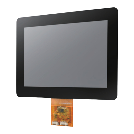
- Page 1 User Manual IDK-1107WP Series TFT-LCD 7” WVGA (LED Backlight) with Projected Capacitive Touchscreen...
- Page 2 No part of this manual may be reproduced, copied, translated or transmitted in any form or by any means without the prior written permission of Advantech Co., Ltd. Information provided in this manual is intended to be accurate and reliable. How- ever, Advantech Co., Ltd.
- Page 3 Whether your new Advantech equipment is destined for the labo- ratory or the factory floor, you can be assured that your product will provide the reliability and ease of operation for which the name Advantech has come to be known.
- Page 4 Because of Advantech’s high quality-control standards and rigorous testing, most of our customers never need to use our repair service. If an Advantech product is defec- tive, it will be repaired or replaced at no charge during the warranty period. For out- of-warranty repairs, you will be billed according to the cost of replacement materials, service time and freight.
- Page 5 Warnings, Cautions, and Notes Warning! Warnings indicate conditions, which if not observed, can cause personal injury! Caution! Cautions are included to help you avoid damaging hardware or losing data. e.g. There is a danger of a new battery exploding if it is incorrectly installed. Replace the battery only with the same or equivalent type recom- mended by the manufacturer.
- Page 6 The sound pressure level at the operator's position according to IEC 704-1:1982 is no more than 70 dB (A). DISCLAIMER: This set of instructions is given according to IEC 704-1. Advantech disclaims all responsibility for the accuracy of any statements contained herein.
-
Page 7: Table Of Contents
Contents Chapter General Description and Features ..1 Display Characteristics................2 Optical Characteristics ................2 Functional Block Diagram ................. 4 Absolute Maximum Ratings ..............5 1.4.1 Absolute Ratings of TFT LCD Module .......... 5 1.4.2 Absolute Ratings of Environment..........5 Outline Dimension..................6 Chapter Electrical Characteristics....7... - Page 8 5.6.3 Operating ..................21 Chapter Touch Controller ....... 23 Touch Controller Characteristics............. 24 Specifications..................24 Table 6.1: Specifications ............24 OS Driver Support................... 25 Circuit board dimension ................25 Interface ....................26 Appendix A Handling Precautions ....... 27 Handling Precautions................28 IDK-1107WP User Manual viii...
-
Page 9: Chapter 1 General Description And Features
Chapter General Description and Features... -
Page 10: Display Characteristics
This manual is for the 7” inch color TFT LCD module IDK-1107WP-50WVA1E which is designed with a wide viewing angle, wide operating temperature, and long life LED backlights which are well suited to display units for Industrial Applications. An LED driving board for the backlight unit is included in this panel and the structure of the LED unit is replaceable. - Page 11 Red x 0.645 Red y 0.341 Green x 0.312 Green y 0.625 Color/Chromaticity Coor- dinates (CIE 1931) - 0.03 +0.03 Blue x 0.153 Blue y 0.053 White x 0.313 White y 0.329 Contrast Gamut Note1 These items are measured by BM-5A(TOPCON) or CA-1000 (MINOLTA) in the dark room (no ambient light) After 5 minutes operation, the optical prop- erties are measured at the center point of the LCD screen.
-
Page 12: Functional Block Diagram
Functional Block Diagram The following diagram shows the functional block of the 7 inches Color TFT-LCD Module: IDK-1107WP User Manual... -
Page 13: Absolute Maximum Ratings
Absolute Maximum Ratings 1.4.1 Absolute Ratings of TFT LCD Module Item Symbol Min. Max. Unit Power Supply Voltage -0.3 [Volt] 1.4.2 Absolute Ratings of Environment Item Symbol Min. Max. Unit Operating Temperature [oC] Operation Humidity [%RH] Storage Temperature [oC] Storage Humidity [%RH] Note 1: Maximum Wet-Bulb should be 38°C and no condensation. -
Page 14: Outline Dimension
Dimensions R7,00(X4) Black Printing area [Unit: mm] IDK-1107WP User Manual... -
Page 15: Chapter 2 Electrical Characteristics
Chapter Electrical Characteristics... -
Page 16: Tft Lcd Module
TFT LCD Module 2.1.1 Power Specification Table 2.1: Power Specification Symbol Parameter Min. Typ. Max. Unit Remark Power Supply Voltage Rush Current RUSH Power Supply Current White Black Note 1: The assembly should be always operated within the above ranges. Note 2: Measurement condition: Note 3: The specified power supply current is under the conditions at Vcc=3.3V, Ta=25±... -
Page 17: Backlight Unit
Backlight Unit 2.2.1 Parameter Guideline for LED Backlight Following characteristics are measured under a stable condition using an inverter at 25°C (Room Temperature): Table 2.3: Parameter Guideline for LED Backlight Parameter Symbol Min. Typ. Max. Unit Remark Converter Power Supply Voltage 10.8 13.2 Converter Power Supply Current... - Page 18 IDK-1107WP User Manual...
-
Page 19: Chapter 3 Signal Characteristics
Chapter Signal Characteristics... -
Page 20: Signal Description
Signal Description LVDS is a differential signal technology for LCD interface and high speed data trans- fer device. The connector pin definition is as below. Note: “Low” stands for 0V. “High” stands for 3.3V. “NC” stands for “No Connected.” 3.1.1 Signal Description Table 3.1: Symbol Description Pin No. -
Page 21: The Input Data Format
The Input Data Format 3.2.1 SEL68 Note1: Please follow PSWG. Note2: R/G/B data 7:MSB, R/G/B data 0:LSB Signal Name Description Remark Red Data 7 (MSB) Red Data 6 Red Data 5 Red-pixel Data Red Data 4 Each red pixel’s brightness data consists of Red Data 3 these 8 bits pixel data. -
Page 22: Interface Timing
Blue Data 7 (MSB) Blue Data 6 Blue Data 5 Blue-pixel Data Blue Data 4 Each blue pixel’s brightness data consists of Blue Data 3 these 8 bits pixel data. Blue Data 2 Blue Data 1 Blue Data 0 (LSB) RxCLKIN+ LVDS Clock Input RxCLKIN-... -
Page 23: Input Timing Diagram
3.3.2 Input Timing Diagram Power ON/OFF Sequence VDD power and lamp on/off sequence is as follows. Interface signals are also shown in the chart. Signals from any system shall be Hi-Z state or low level when VDD is off. Parameter Value Unit Min. - Page 24 [ms] [ms] [ms] The above on/off sequence should be applied to avoid abnormal function in the dis- play. Please make sure to turn off the power when you plug the cable into the input connector or pull the cable out of the connector. Note 1: The supply voltage of the external system for the module input should be the same as the definition of VDD Note 2: Apply the lamp voltage within the LCD operation range.
-
Page 25: Chapter 4 Display Connector Definition
Chapter Display Connector Definition... -
Page 26: Tft Lcd Signal (Cn1): Lvds Connector
TFT LCD Signal (CN1): LVDS Connector Table 4.1: TFT LCD Signal (CN1): LVDS Connector Connector Name / Description Signal Connector Manufacturer Starconn or compatible Mating Model Number 076B20-0048RA-G4, Starconn or equivalent Table 4.2: Pin Assignment Pin No. Signal Name Pin No. Signal Name RX3+ RX3-... -
Page 27: Chapter 5 Touch Screen
Chapter Touch Screen... -
Page 28: Touch Characteristics
Touch Characteristics This touch panel is a resistance type that customers use with flat displays like LCDs. Once an operator touches it, the circuit sends coordinate points to the PC from the voltage at contact points. Optical Characteristics Item Specification Remarks TRANSPARENCY 90% ±... -
Page 29: Mounting Notes
Mounting Notes 5.6.1 Mounting The gasket of the touch panel must be designed for the outside of the viewable area to avoid pressing on the touch panel accidentally and the enclosure must be designed with enough clearance from the panel surface. To avoid pressing errors on the touch panel, please allow space between the surface of the panel and the bezel. - Page 30 Avoid applying excessive activation force or sudden impact on the panel sur- face. Avoid high voltages and / or static charge. 5.6.3.1 Others Keep the panel surface clean. Prevent any kind of adhesive or tape applied onto the touch surface.
-
Page 31: Chapter 6 Touch Controller
Chapter Touch Controller... -
Page 32: Touch Controller Characteristics
Touch Controller Characteristics EETI EXC3132 is a MCU based projected capacitive touch screen controller designed for commercial and industrial applications. EXC3132 controller supports high voltage driving signal to achieve high SNR and better wideband interference susceptibility. EXC3132 provides different working frequencies to avoid narrow band interference. With high voltage driving and different working frequencies, EXC3132 provides excellent interference susceptibility performance. -
Page 33: Os Driver Support
OS Driver Support Version Interfaces Windows 7/ 8/10 Windows Vista, XP/2000, 9x/ME Windows Windows CE 2.12/3.0/.net/5.0/6.0 Windows Embedded Windows XP Tablet PC edition Mandrake (Mandrake 9.1/9.2/10, Mandriva 2005, Mandriva 2006), Red Hat (7.3/8.0/9.0), Fedora (Core I/II/III/IV/V/VI), Yellow Dog (3.X) , (up to Kernel 2.6.x) Linux SuSE (9.2/9.3/10/10.1),... -
Page 34: Interface
Interface IDK-1107WP User Manual... -
Page 35: Appendix A Handling Precautions
Appendix Handling Precautions... -
Page 36: Handling Precautions
Handling Precautions The optical characteristics are measured under stable conditions at 25°C (Room Temperature) Since front polarizer is easily damaged, pay attention not to scratch it. Be sure to turn off power supply when inserting or disconnecting from input con- nector. - Page 37 No part of this publication may be reproduced in any form or by any means, electronic, photocopying, recording or otherwise, without prior written permis- sion of the publisher. All brand and product names are trademarks or registered trademarks of their respective companies. © Advantech Co., Ltd. 2016...
Need help?
Do you have a question about the IDK-1107WP Series and is the answer not in the manual?
Questions and answers