
Related Manuals for Aruba 8325 Series


Summary of Contents for Aruba 8325 Series
- Page 1 Aruba 8325 Switch Series Installation and Getting Started Guide Part Number: 5200-5297 Published: January, 2019 Edition: 1...
- Page 2 © 2019 Hewlett Packard Enterprise Development LP Notices The information contained herein is subject to change without notice. The only warranties for Hewlett Packard Enterprise products and services are set forth in the express warranty statements accompanying such products and services. Nothing herein should be construed as constituting an additional warranty. Hewlett Packard Enterprise shall not be liable for technical or editorial errors or omissions contained herein.
-
Page 3: Table Of Contents
Contents Chapter 1 About this document ................ Applicable products ............................ Related publications ........................... Chapter 2 Introducing the Aruba 8325 Switch ..........Overview ..............................Front of the switch ............................8325-48Y8C JL624A and JL625A switches..................8325-32C JL626A and JL627A switches .................... Network ports ............................ - Page 4 Chapter 8 Support and other resources ............Accessing Hewlett Packard Enterprise support ..................Before calling support ..........................Accessing updates ........................... Websites ..............................Customer self repair ..........................Remote support ............................Documentation feedback .......................... Aruba 8325 Switch Installation and Getting Started Guide...
-
Page 5: Chapter 1 About This Document
Aruba 8325-32C 32-port 100G QSFP+/QSFP28 Back-to-Front JL627A 6 Fans and 2 Power Supply Bundle Related publications • START HERE: Installation, Safety, and Regulatory Information for the Aruba 8325 Switches • ArubaOS-Switch and ArubaOS-CX Transceiver Guide • Aruba 8325 Fundamentals Guide for ArubaOS-CX 10.02 (or greater) •... - Page 6 Aruba 8325 Switch Installation and Getting Started Guide...
-
Page 7: Chapter 2 Introducing The Aruba 8325 Switch
Introducing the Aruba 8325 Switch Overview The Aruba 8325 switch is a multiport switch that can be used to build high-performance switched networks. The switch is a store-and-forward device offering low latency for high-speed networking. The Aruba 8325 switch also supports full network management capabilities. -
Page 8: Front Of The Switch
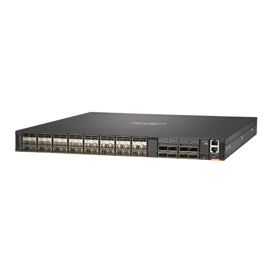
◦ Management software Front of the switch 8325-48Y8C JL624A and JL625A switches Figure 1: Front of the Aruba 8325-48Y8C (JL624A and JL625A) Table 1: Front of the Aruba 8325-48Y8C (JL624A and JL625A) Label Description Power Supply 1 and 2 (PS1/PS2), Fan, Global Status, and Unit Identification LEDs SFP28 ports (these ports also support SFP+ transceivers) SFP28 port LEDs. - Page 9 Reset button Interface-Group operation The SFP28 ports in the Aruba 8325-48Y8C switches are organized into four groups of 12 ports each. Figure 2: Front of the Aruba 8325-48Y8C (JL624A and JL625A) interface-groups Table 2: Aruba 8325-48Y8C (JL624A and JL625A) interface-groups...
-
Page 10: 8325-32C Jl626A And Jl627A Switches
8325-32C JL626A and JL627A switches Figure 3: Front of the Aruba 8325-32C (JL626A and JL627A) Table 3: Front of the Aruba 8325-32C (JL626A and JL627A) Label Description Power Supply 1 and 2 (PS1/PS2), Unit Identification, Global Status, and Fan LEDs... -
Page 11: Part Number
– – – – – Direct Attach (twinaxial) 25-Gig SR Fiber – – – – (multimode) 25-Gig eSR Fiber – – – – (multimode) 25-Gig LR Fiber (single – – – – mode) Chapter 2 Introducing the Aruba 8325 Switch... - Page 12 -maximum eight 10GBase-T transceivers RJ-45 shielded Cat 6A cable is needed for connecting up this transceiver. The max link length specified is 30m. CAT6A F/FTP, S/FTP, SF/FTP highly recommended in noisy environments. Refer to Aruba Support_Advisory_JL563A_10GBaseT_APSC-RS20180403-01 for more information. The Lucent Connector (LC) is a small form factor fiber optic connector.
-
Page 13: Management Ports
Management ports Console port The Aruba 8325-48Y8C and 8325-32C switches include an RJ-45 serial console port. This port is used to connect a console to the switch by using an RJ-45 serial cable (not supplied). A DB9-to-RJ-45 console cable can be ordered from HPE: JL448A, Aruba X2C2 RJ45 to DB9 Console Cable. - Page 14 Table 6: Chassis LED labels for the Aruba 8325-48Y8C (JL624A and JL625A) Label Description Power Supply 1 (PS1) LED Power Supply 2 (PS2) LED Fan LED Global Status LED Unit Identification LED Figure 5: Chassis LEDs for the Aruba 8325-32C (JL626A and JL627A)
- Page 15 LED. to identify a particular The “LED locator flashing” unit in a rack or command will flash the LED. collection of products. The "LED locator off" command turns off the LED. Chapter 2 Introducing the Aruba 8325 Switch...
-
Page 16: Port Leds On The Front Of The Switch
Port LEDs on the front of the switch Figure 6: Port LEDs for the Aruba 8325-48Y8C (JL624A and JL625A) Table 9: Port LED labels for the Aruba 8325-48Y8C (JL624A and JL625A) Label Description Upper SFP28 port LED Middle SFP28 port LED... - Page 17 Table 10: Port LED behavior for the Aruba 8325-48Y8C (JL624A and JL625A) Chassis LEDs Function State Meaning SFP28 port LEDs To display link and On/flashing green Shows a valid link at 25/10 Gbps. activity information for • Fast flashing indicates port the port.
- Page 18 Figure 7: Port LEDs for the Aruba 8325-32C (JL626A and JL627A) Table 11: Port LED labels for the Aruba 8325-32C (JL626A and JL627A) Label Description QSFP28 port LED and lane 1 indicator QSFP28 lane 2 LED (Not supported with currently released software.) QSFP28 lane 3 LED (Not supported with currently released software.)
-
Page 19: Reset Button
Switch product label The switch product label is an Aruba Orange-colored tab on the bottom right side of the switch front panel. Pull the tab out to view the product label information. -
Page 20: Back Of The Switch
The back of the switch includes two power supply units and six fan assemblies. Figure 9: Back of the Aruba 8325-48Y8C (JL624A and JL625A) Table 14: Back of the Aruba 8325-48Y8C (JL624A and JL625A) switch labels and descriptions Label Description... - Page 21 Table 14: Back of the Aruba 8325-48Y8C (JL624A and JL625A) switch labels and descriptions (Continued) Label Description Fan assembly 3 Fan assembly 2 Fan assembly 1 Power supply status LED Power supply 1 Ground lug Fan assembly status LED Color-coded power supply release latch...
-
Page 22: Power Supplies
Power supplies The Aruba 8325 switch does not have a power switch; it is powered on when at least one installed power supply is connected to an active AC power source. The power supplies automatically adjust to any voltage between 100-127 and 200-240 volts and either 50 or 60 Hz. -
Page 23: Fan Assemblies
Redundancy With power redundancy, the Aruba 8325 switch can continue normal operation even when one power supply fails or is powered off. When two power supplies are installed, if one becomes unavailable (fails, or is powered off or removed) the remaining power supply provides full power for the device. - Page 24 If one or more of the fan assemblies have failed, the front-panel Fan LED will be on amber and failed fan assembly LEDs will be on red. If multiple fans have failed, the switch should be immediately powered off and the fan assemblies replaced. Aruba 8325 Switch Installation and Getting Started Guide...
- Page 25 The Aruba 8325 switch is not compatible with fan assemblies from other Aruba hardware platforms. Fan assembly status LED Table 20: Fan assembly LED behavior Fan assembly LED Function State Meaning Status LED To display fan assembly On green The fan assembly is operating status.
-
Page 26: Switch Features
Switch features The features of the Aruba 8325 switch include: • Combinations of fixed QSFP28 and SFP28 ports, as described under Network ports. • For secure environment, all ports are disabled by default. • The option to have one or two power supplies: A second power supply supports redundant system power. If one of the power supplies fails, the second power supply immediately provides the power necessary to keep the switch running. -
Page 27: Chapter 3 Installing The Switch
Installing the switch This chapter shows how to install the switch. The Aruba 8325 switch requires you to order a rack mount kit that includes the brackets for mounting the switch in a standard 19-inch telco rack, or in an equipment cabinet. -
Page 28: Installation Procedures
10. Connect the network devices (page 43). Using the appropriate network cables, connect the network devices to the switch ports. At this point, your switch is fully installed. See the rest of this chapter if you need more detailed information on any of these installation steps. Aruba 8325 Switch Installation and Getting Started Guide... -
Page 29: Installation Precautions
Installation precautions To avoid personal injury or product damage when installing your switch, read the installation precautions and guidelines below. • Do not mount the switch on a wall, on or under a table, or on or under any other horizontal surface. -
Page 30: Prepare The Installation Site
On the sides of the switch, leave at least 3 inches (7.6 cm) for cooling. Cooling air flow in Aruba 8325 switches is Front-to-Back (FB) or Back-to-Front (BF), depending on which power supply and fan assembly options are installed. To reverse the cooling air flow direction in an 8325 switch, you must replace the existing power supplies and fan assemblies with power supplies and fan assemblies having the opposite air flow direction. -
Page 31: Install Fan Assemblies
3. Install fan assemblies Skip this step if all six fan slots are already populated with fan assemblies. Use the following steps to install a fan assembly in any empty fan slot. • The 48-port switches and the 32-port switches use different fan assemblies. Each fan assembly type can only be installed in the correct switch model. -
Page 32: Power-On The Switch And Check Leds
4. Power-on the switch and check LEDs An Aruba 8325 switch does not contain a power on/off switch. It is turned on by connecting the AC power cord to the switch and to an AC power source. Figure 15: Connecting power to the switch Check LEDs for proper switch operation. - Page 33 Table 21: Chassis LED labels for the Aruba 8325-48Y8C (JL624A and JL625A) (Continued) Label Description PS2 LED: Green after power on, unless the power supply is in a fault state, or not receiving power. Fan LED: Green after power on, unless a fan on the back of the unit is in a fault state.
-
Page 34: Power Off The Switch
Table 22: Chassis LED labels for the Aruba 8325-32C (JL626A and JL627A) Label Description Fan LED: Green after power on, unless a fan on the back of the unit is in a fault state. 5. Power off the switch Remove the power cord from the switch and from the power source. - Page 35 Figure 19: Mounting the switch in a two-post rack Four-post rack mount option: The Aruba 8325 switch can be mounted in four-post racks and cabinets by using the Aruba X474 4-Post Rack Kit (JL483B); sold separately. The JL483B Aruba X474 4-Post Rack Kit includes these items: •...
- Page 36 3. Hold the switch with attached brackets up to the rack, move it vertically until rack holes line up with the front- post bracket holes, and then insert and tighten the four number 12-24 screws holding the brackets to the rack. Aruba 8325 Switch Installation and Getting Started Guide...
-
Page 37: Install Transceivers
Figure 21: Mounting the switch in a four-post rack 4. Adjust the rear-post bracket ears to fit the depth of the rack. 5. Secure the rear-post brackets to the rack rear posts using four number 12-24 screws. 6. Lock the position of the rear-post bracket ears using the included position-locking screws. Figure 22: Locking the position of rear-post brackets 7. -
Page 38: Interface-Group Speed Settings
Use only supported genuine Aruba SFP+/SFP28/QSFP+/QSFP28 transceivers with your switch. Non- Aruba transceivers are not supported, and their use may result in product malfunction. Should you require additional transceivers, contact your Aruba sales representative or an authorized reseller. For more transceiver support information for your switch model, see the ArubaOS-Switch and ArubaOS-CX Transceiver Guide in the Hewlett Packard Enterprise Information Library at http:// www.hpe.com/networking/ResourceFinder. -
Page 39: Installing Transceivers
For more information, and to view or change the speed setting for a port group, see the Aruba 8325 Fundamentals Guide for ArubaOS-CX 10.02 or later at www.hpe.com/networking/ResourceFinder. -
Page 40: Removing Transceivers
8. Connect the switch to a power source 1. If a power supply is not already installed in the switch, install at least one power supply. (See “2. Install power supplies” on page 30.) The Aruba 8325 switch uses any of the following power supplies: •... -
Page 41: Connect A Management Console
AC power sources, redundant power can be supplied in case of loss of one of the AC power sources. 9. Connect a management console The Aruba 8325 switch has a full-featured, easy to use console interface for performing switch management tasks, including the following: •... -
Page 42: Direct Console Access
Password: switch# If you want to continue with console management of the switch at this time, see the Aruba 8325 Fundamentals Guide for ArubaOS-CX for initial configuration steps. For more detailed information, refer to the switch software manuals for your switch provided at www.hpe.com/networking/ResourceFinder. -
Page 43: Console Cable Pinouts
Console cable pinouts The Aruba X2C2 RJ45 to DB9 Console Cable (JL448A) has an RJ-45 plug on one end and a DB-9 female connector on the other end. Table 24 describes the mapping of the RJ-45 to DB-9 pins. Figure 27: RJ-45 to DB-9 pinouts... -
Page 44: Connecting Cables To Transceivers
If the port LED does not come on when the network cable is connected to the port, see “Diagnosing with the LEDs” on page 50 in the Troubleshooting chapter. Figure 29: Connecting cable to a transceiver Aruba 8325 Switch Installation and Getting Started Guide... -
Page 45: Chapter 4 Replacing Components
If the Aruba 8325 switch is configured with a redundant power supply, the switch will not suffer any loss of traffic or performance if a power supply fails. To maintain system redundancy, a failed power supply should be replaced as soon as possible. -
Page 46: Replacing A Fan Assembly
4. Connect the AC power cable to the new power supply’s connector. Replacing a fan assembly The Aruba 8325 switch is equipped with six field-replaceable, hot-swappable fan assemblies. The switch can tolerate the failure of a single fan assembly while maintaining a safe operating temperature. To maintain system redundancy, a failed fan assembly should be replaced as soon as possible. - Page 47 1. Identify the failed fan assembly by its status LED. The fan assembly LED will be on red, or flashing red. 2. Remove the new fan assembly from its packaging, being careful to not touch any of the circuitry on the board. 3.
- Page 48 Aruba 8325 Switch Installation and Getting Started Guide...
-
Page 49: Chapter 5 Troubleshooting
You can perform more in-depth troubleshooting on these devices using the software tools available with the switches, including the full-featured console interface, the built-in web browser interface, and IMC, the SNMP-based network management tool, or Aruba AirWave. This chapter describes the following: •... -
Page 50: Diagnosing With The Leds
If the power source and power cord are OK and this condition persists, the switch power supply may have failed. Call your Hewlett Packard Enterprise- authorized network reseller, or use the electronic support services from Hewlett Packard Enterprise to get assistance. Aruba 8325 Switch Installation and Getting Started Guide... - Page 51 Problem Solution One of the switch fan Try disconnecting power from the switch and wait a few moments. Then assemblies may have reconnect the power to the switch and check the LEDs again. If the error failed. indication reoccurs, one of the fan assemblies has failed. The switch may continue to operate under this condition if the ambient temperature does not exceed normal room temperature, but for best operation, the fan assembly should be replaced.
- Page 52 Ensure also, that the device at the other end of the connection is indicating a good link to the switch. If it is not, the problem may be with the cabling between the devices or the connectors on the cable. Aruba 8325 Switch Installation and Getting Started Guide...
-
Page 53: Hardware Diagnostic Tests
Hardware diagnostic tests Testing the switch by resetting it If you believe the switch is not operating correctly, you can reset the switch to test its circuitry and operating code. To reset a switch, either: • unplug and plug in the power cord (power cycling) •... -
Page 54: Battery
To locate this guide, visit http://www.hpe.com/networking/ResourceFinder and filter for switches, switch model, and information type. • If the battery fails and you want to replace it, contact your authorized Aruba representative for assistance. Batteries are not customer-serviceable. Battery failures should only be referred to service personnel authorized by Aruba. -
Page 55: Chapter 6 Specifications
The power supply automatically adjusts to any voltage between 100-240 volts and either 50 or 60 Hz. Power Consumption Product Power consumption Aruba 8325-48Y8C FB 6 F 2 PS Bdl (JL624A) Max: 550 W, 1877 BTU/hr Idle: 209 W, 713 BTU/hr Aruba 8325-48Y8C BF 6 F 2 PS Bdl (JL625A) -
Page 56: Mtbf
(non-condensing) condensing Maximum altitude 3.0 km (10,000 ft)* 4.6 km (15,000 ft) * The operating maximum altitude should not exceed that of any accessory being connected to any Aruba 8325 switch. Acoustics Switch Model Acoustics Aruba 8325-48Y8C FB 6 F 2 PS Bdl (JL624A) Sound Pressure (LpAm) (Bystander) 90.8 dB... -
Page 57: Standards
Standards Table 28: Technology standards and safety compliance Laser safety information Technology Compatible with these IEEE EN/IEC standard Lasers standards compliance 10GBASE-T IEEE 802.3an 10GBASE-T – – 10GBASE-SR IEEE 802.3ae 10GBASE-SR EN/IEC 60825 Class 1 Laser Product Laser Klasse 1 10GBASE-LR IEEE 802.3ae 10GBASE-LR EN/IEC 60825... - Page 58 Aruba 8325 Switch Installation and Getting Started Guide...
-
Page 59: Chapter 7 Cabling And Technology Information
See Note on 10GBASE-T cable requirements below, and see “Technology distance specifications” on page 60 for distances supported with each cable type. CAT6A F/FTP, S/FTP, SF/FTP highly recommended in noisy environments. Refer to Aruba Support_Advisory_JL563A_10GBaseT_APSC-RS20180403- 01 for more information. Twinaxial copper... -
Page 60: Technology Distance Specifications
Category 6A patch cables, or using cable management options to tie down (dress) the Category 6 patch cables so they cannot move. For Conducted and Radiated Immunity in accordance with EN55024, the Aruba switch is limited to Performance Criteria A with shielded cables (CAT6A). - Page 61 Table 30: Technology distance specifications (Continued) Technology Supported cable type Multimode fiber Supported distances modal bandwidth 10GBASE-SR multimode fiber 160 MHz*km 2 - 26 meters 200 MHz*km 2 - 33 meters 400 MHz*km 2 - 66 meters 500 MHz*km 2 - 82 meters 2000 MHz*km 2 - 300 meters 10GBASE-LR...
- Page 62 Aruba 8325 Switch Installation and Getting Started Guide...
-
Page 63: Chapter 8 Support And Other Resources
Chapter 8 Support and other resources Accessing Hewlett Packard Enterprise support • For live assistance, go to the Contact Hewlett Packard Enterprise Worldwide Support website: www.hpe.com/assistance • To access documentation and support services, go to the Hewlett Packard Enterprise Support Center website: www.hpe.com/support/hpesc Information to collect •... -
Page 64: Accessing Updates
CSR. Your Hewlett Packard Enterprise authorized service provider will determine whether a repair can be accomplished by CSR. For more information about CSR, contact your local service provider or go to the CSR website: www.hpe.com/support/selfrepair Aruba 8325 Switch Installation and Getting Started Guide... -
Page 65: Remote Support
Remote support Remote support is available with supported devices as part of your warranty, Care Pack Service, or contractual support agreement. It provides intelligent event diagnosis, and automatic, secure submission of hardware event notifications to Hewlett Packard Enterprise, which will initiate a fast and accurate resolution based on your product’s service level.
Need help?
Do you have a question about the 8325 Series and is the answer not in the manual?
Questions and answers