Table of Contents
Advertisement
Quick Links
SERVICE MANUAL
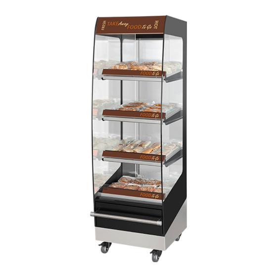
MULTI DECK 60 HOT WITH GLASS FRONT
WWW.FRIJADO.COM
Multi Deck 60 Glass front door
This manual is prepared for the use of trained Service Technicians and
should not be used by those not properly qualified. If you have atten-
ded a trianing for this product, you may be qualified to perform all the
procedures in this manual.
This manual is not intended to be all encompassing. If you have not
attended a training for this product, you should read, in its entirety, the
repair procedure you wish to performto determine if you have the ne-
cessary tools, instruments and skills required to perform the procedure.
Procedures for which you do not have the necessary tools, instruments
and skills should be performed by a trained technician.
Reproduction or other use of this Manual, without the express written
consent of Fri-Jado, is prohibited.
DOOR
- NOTICE -
Service Manual Multi Deck 60 UK form 9123765 rev.12/2008
Advertisement
Table of Contents

Related Manuals for Fri-Jado MD 60 Hot


Summary of Contents for Fri-Jado MD 60 Hot
- Page 1 Procedures for which you do not have the necessary tools, instruments and skills should be performed by a trained technician. Reproduction or other use of this Manual, without the express written consent of Fri-Jado, is prohibited. WWW.FRIJADO.COM Service Manual Multi Deck 60 UK form 9123765 rev.12/2008...
- Page 2 Page 2 Service Manual Multi Deck 60 UK form 9123765 rev. 12/2008...
-
Page 3: Table Of Contents
TABLE OF CONTENTS InDEx Index ............................3 General technical data ........................ 4 Technical Data ............................4 Removal and replacement of parts ..................5 Panels bottom side ..........................5 Cover plate on field wiring box ......................5 Illumination/tumble switch ........................6 Electronic ballast/Interference filter ..................... -
Page 4: General Technical Data
All of the information, illustrations and specifications contained in this manual are based on the latest product information available at the time of printing. TECHNICAL DATA Type MD 60 Hot Power (W) 3100 Fuses needed with power connection 1x 13 A... -
Page 5: Removal And Replacement Of Parts
Removal and replacement of parts REMovAl AnD REPlACEMEnT of PARTS WARNING: Disconnect the electrical power to the machine at the main circuit box. Place a tag on the circuit box indica- ting the circuit is being serviced. PANELS bOTTOM SIDE 1. -
Page 6: Illumination/Tumble Switch
Removal and replacement of parts ILLUMINATION/TUMbLE SWITCH 1. Remove the socket screws on the top side and turn light fixture towards yourself. 2. Replace lamp. 3. Remove wiring from switch and remove the switch by pushing the clamps on both sides. -
Page 7: Back Panels
Removal and replacement of parts bACK PANELS 1. Remove the screws that secure the back panel and remove this panel. 2. Remove the insulation. 3. Remove the screws that secure the cover panel and remove this panel. 4. Reverse the procedure to install. THERMOSTAT (DANFOSS) 1. -
Page 8: Sensor Danfoss Thermostat
Removal and replacement of parts SENSOR DANFOSS THERMOSTAT 1. Remove the thermostat according prior procedure. 2. Remove the back panels + insulation + cover panel. 3. Remove the panels on the bottom side. 4. Remove the holder with sensor (use a drill of 3.2 mm.) 5. -
Page 9: Blower Shelf Heating
Removal and replacement of parts bLOWER SHELF HEATING 1. Remove the electric panel and all panels on the bottom side according prior proce- dures. 2. Remove the socket screws from the ben- ded plate and fastening plate and remove these plates. 3. -
Page 10: Heating Element
Removal and replacement of parts HEATING ELEMENT 1. Remove the back panels, insulation, cover plate and the thermostat sensor according prior procedures. 2. Remove all the panels on the bottom side side + the back panel on bottom side ac- cording prior procedures. -
Page 11: Safety Thermostat (Reset)
Removal and replacement of parts SAFETy THERMOSTAT (RESET) 1. Remove the electric panel, back panels, insulation and cover plate, and the cover plate on the field wiring box according prior procedures. 2. Remove the clip on the sensor and remo- ve the sensor. -
Page 12: Replacing Side Glass
Removal and replacement of parts Replacing a side glass in the MD REPLACING SIDE GLASS Remove all traces of glass and silicone past. Remove the product stopper from the bottom Remove the six screws from the top plate. plate. - Page 13 Removal and replacement of parts Putting the new glass in place Attach all nuts B by hand. Hold nut B in position using a spanner. Tighten nut A firmly using a spanner. Put the insulation plates in the top ! ...
-
Page 14: Replacing The Glass Door
Removal and replacement of parts REPLACING THE GLASS DOOR 1. open the door and press the spring of the hinge pin down with a screw driver(picture 1+2). Move the door a bit towards yourself until the pin comes out of the hole. Hold the door to prevent it from falling. -
Page 15: Electrical Tests And Service Procedures
ELECTRICAL TESTS AND SERVICE PROCEDURES ElECTRICAl TESTS AnD SERvICE PRoCEDuRES WARNING: Disconnect the electrical power to the machine at the main cir- cuit box. Place a tag on the circuit box indicating the circuit is being serviced. HEATING ELEMENT TEST Note: When testing the resistance of the element remove the wiring. - Page 16 ELECTRICAL TESTS AND SERVICE PROCEDURES Replacing of thermostat When you install a new thermostat, then always change parameter r05 first to 0 (°C) and change parameter o07 to HE. otherwise some other parameters cannot be changed to the desired value. otherwise some other parameters cannot be changed to the desired value. You can run through the parameters with the up or down keys, once you are inside the para meter settings.
- Page 17 ELECTRICAL TESTS AND SERVICE PROCEDURES Access code all settings Sensor type Warm (HE) / cold (rE) Step value display (yes = 0.5°C / no = 1°C) Store parameters under number Restore parameters as stored Store current parameter as factory default Status relay 1 Page 17 Service Manual Multi Deck 60 UK form 9123765 rev.
-
Page 18: Control Locations
ELECTRICAL TESTS AND SERVICE PROCEDURES CONTROL LOCATIONS heating switch light switch thermostat EKC 102A Service Manual Multi Deck 60 UJK form 9123765 rev. 12/2008 Page 18... -
Page 19: Troubleshooting
TROUBLESHOOTING TRouBlESHooTInG TROUbLE SHOOTING MULTI DECK 60 WITH GLASS DOOR Symptom Possible causes no power to cabinet controls. 1. Main breaker open. 2. Wiring loose. Main fuse or breaker blows. 1. Wiring incorrectly. 2. Heating element shorted. 3. Wiring shorted. Illumination does not work. - Page 20 TROUBLESHOOTING This is an analytic description for servicing and repairing all major parts of the Multi Deck 60. 1. Symptoms. 2. Possible causes. 3. Solving of the problem: checking/action. 4. Replacing of parts and testing: a. Replacing is described in this service manual. b.
-
Page 21: Exploded Views & Partlists
EXPLODED VIEWS AND PARTLISTS ExPloDED vIEWS & PARTlISTS Multi Deck 60 UK Hot Assembly Drawing Service Manual Multi Deck 60 UK form 9123765 rev. 12/2008 Page 21... - Page 22 EXPLODED VIEWS AND PARTLISTS ITEM PART NO DESCRIPTION 9222012 Protection plate dia, transparent 9222011 Protection plate, illumination inside 9181008 Switch, tumble 9221013 Interference filter 9181071 Sticker, light 9181072 Sticker, heat 9082897 Lamp holder 9160019 Lamp, PLL 55 W 9220084 Front door, ass. 9222146 Glass 9224149...
- Page 23 EXPLODED VIEWS AND PARTLISTS ITEM PART NO DESCRIPTION 9225076 Panel 9225071 Bottom plate, bended 9224097 Bracket, temperature probe 9222048 Rubber gasket 9220048 Glass panel, left, ass. 9220049 Glass panel, right, ass. 9225029 Front plate bottom 9223053 Bumper 9171014 Plug 9223054 Spacer 9225025 Front panel underframe...
-
Page 24: Electrical Diagrams
Electrical Diagrams ElECTRICAl DIAGRAMS Service Manual Multi Deck 60 UK form 9123765 rev. 12/2008 Page 24... - Page 25 Electrical Diagrams Service Manual Multi Deck 60 UK form 9123765 rev. 12/2008 Page 25...
- Page 26 Fri-Jado B.V. • P.O. Box 560 • 4870 AN • Etten-Leur • The Netherlands • tel +31 76 50 85 400 • fax +31 76 50 85 444 • info@frijado.com • www.frijado.com...
Need help?
Do you have a question about the MD 60 Hot and is the answer not in the manual?
Questions and answers