Table of Contents
Advertisement
Quick Links
CS-D507E
Closed Loop Stepper Drive
User Manual
Revision 1.0
©2020 Leadshine Technology Co., Ltd.
Address: 15-20/F, Block B, Nanshan I Valley, No.3185, Shahe West Road, Nanshan District,
Shenzhen, Guangdong, 518055, China
Tel: (86)755-26409254
Fax: (86)755-26402718
Web:
www.leadshine.com
Sales:
sales@leadshine.com
Support:
tech@leadshine.com
Advertisement
Table of Contents

Subscribe to Our Youtube Channel
Related Manuals for Leadshine Technology CS-D507E


Summary of Contents for Leadshine Technology CS-D507E
- Page 1 CS-D507E Closed Loop Stepper Drive User Manual Revision 1.0 ©2020 Leadshine Technology Co., Ltd. Address: 15-20/F, Block B, Nanshan I Valley, No.3185, Shahe West Road, Nanshan District, Shenzhen, Guangdong, 518055, China Tel: (86)755-26409254 Fax: (86)755-26402718 Web: www.leadshine.com Sales: sales@leadshine.com Support:...
- Page 2 CS-D507E Closed Loop Stepper Drive User Manual Notice Read this manual carefully before any assembling and using. Incorrect handling of products in this manual can result in injury and damage to persons and machinery. Strictly adhere to the technical information regarding installation requirements.
-
Page 3: Table Of Contents
CS-D507E Closed Loop Stepper Drive User Manual Table of Content 1. Introduction..................................1 1.1 Features...................................1 1.2 Applications................................1 2. Specifications...................................2 2.1 Electrical Specifications............................2 2.2 Environment................................2 2.3 Mechanical Specifications............................3 2.4 Heat Dissipation..............................3 3. Connections and LED Indication..........................4 3.1 Connector P1 – Control Signals and Digital Outputs Connector................4 3.1.1 Pin Assignments of P1..........................4... - Page 4 8. Sequence Chart of Control Signals..........................12 9. Fault Protections................................12 10. Software Configuration..............................13 11. Accessories................................... 13 12. Troubleshooting................................14 13. Warranty..................................16 Appendix A. Leadshine CS-D507E Compatible Stepper Motors................17 Appendix B. Leadshine CS-D507E Compatible Power Supplies................18 Appendix C. Powering a Third-Party Motor with CS-D507E..................18...
-
Page 5: Introduction
CS-D507E Closed Loop Stepper Drive User Manual 1. Introduction Leadshine CS-D507E is a closed loop stepper drive designed to solve the loss of step problem in open loop stepper control systems, thus increase system reliability at minimal cost increase. It implements advanced control algorithm of Leadshine based on its tens of years’... -
Page 6: Specifications
CS-D507E Closed Loop Stepper Drive User Manual 2. Specifications 2.1 Electrical Specifications Parameters Typical Unit Output Current (peak) Operating Voltage 24, 36, 48 Logic signal current Pulse input frequency (5V @ 50% dutycycle) Pulse input frequency (24V @ 50% dutycycle) 1μS @ 5V,... -
Page 7: Mechanical Specifications
It is recommended to mount the drive vertically to maximize heat dissipation. Mount a cooling fan nearby if necessary. If multiple CS-D507E drives are installed, it is suggested to keep a minimal 30mm (1.2 inches) between two of them. -
Page 8: Connections And Led Indication
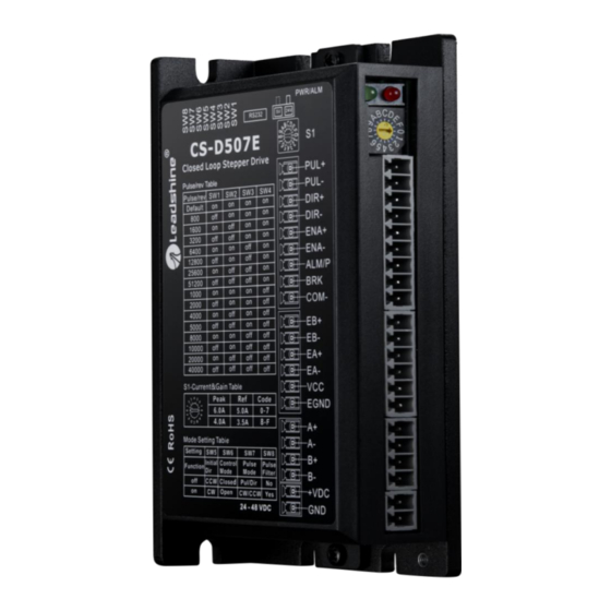
CS-D507E Closed Loop Stepper Drive User Manual 3. Connections and LED Indication A CS-D507E closed loop stepper drive has 5 connection blocks from P1 to P5 (see figure 2). Figure 2: CS-D507E connectors 3.1 Connector P1 – Control Signals and Digital Outputs Connector 3.1.1 Pin Assignments of P1... -
Page 9: Connection Of Control Signals
3.1.2 Connection of Control Signals The CS-D507E can accept differential and single-ended control signal inputs (open-collector and PNP output). A CS-D507E has 3 optically isolated control inputs, PUL, DIR, and ENA. Refer to the following two figures for connections of open-collector and PNP signals. -
Page 10: Connection Of Brk Signal
CS-D507E Closed Loop Stepper Drive User Manual Use LeadshineMotionStudio software to configure this output as an IN POSITION output. In this case, an output signal can be sent out when the targeted position is in the “Target” range (see parameter Distance to Send "In position"... -
Page 11: Connector P2 - Encoder Connection
CS-D507E Closed Loop Stepper Drive User Manual 3.2 Connector P2 - Encoder Connection The P2 connector in Figure 2 is for encoder signal connection. Refer to the following table for details. Drive Pin Name Description Encoder B+ input connection Encoder B- input connection... -
Page 12: Led Light Indication
3.6 LED Light Indication There are two LED lights for CS-D507E, one red and one green. The GREEN one is the power indicator which will be always on generally. The RED one is a protection indicator. It is off always when a CS-D507E operates normally, but will flash 1, 2 or 7 times in a 5-second period when error protection is enabled. -
Page 13: Regulated Or Unregulated Power Supply
5.2 Power Supply Sharing Multiple CS-D507E drives can share one power supply to save space and reduce cost, if that power supply has enough power capacity. To avoid cross interference, connect each stepper drive directly to the shared power supply separately. -
Page 14: S2 - Dip Switch Configurations
Pulse mode Control mode Figure 6: DIP switches 6.2.1 Micro Step (SW1-SW4) Each CS-D507E has 15 microstep settings which can be configured through DIP switches SW1, SW2, SW3 and SW4. See the following table for detail. Micro step Pulses/Rev. (for 1.8°motor) -
Page 15: Mode Setting (Sw5 - Sw8)
Yes (10ms) No (1.5ms) Remark: (1) CS-D507E supports open-loop mode, which can be used when the encoder is damaged or judging whether the value of the position loop gain is wrong; (2) “Pulse Filter Time” means S-curve acceleration, to improve motion smoothness and high-speed start frequency in many circumstances. -
Page 16: Sequence Chart Of Control Signals
CS-D507E Closed Loop Stepper Drive User Manual Figure 7: Typical connection 8. Sequence Chart of Control Signals In order to avoid some fault operations and deviations, PUL, DIR and ENA should abide by some rules, shown as following diagram: Figure 8: Sequence chart of control signals Remark: (1) t1: ENA must be ahead of DIR by at least 500ms. -
Page 17: Software Configuration
10. Software Configuration The CS-D507E is designed for simple setup and implementation. For most applications, no software configuration or tuning is needed especially when driving Leadshine stepper motors with encoders (see Appendix A). If you want to do fine tuning or custom configurations such as micro-step, current percentage change…, you can use Leadshine’s free... -
Page 18: Troubleshooting
CS-D507E Closed Loop Stepper Drive User Manual USB to RS232 conversion, contact your supplier or Leadshine for such a cable with part number USB2.0-232 which has been verified working fine. CABLE-PC-1 USB2.0-232 (RS232 tuning cable) (USB to RS232 Conversion Cable) 12. - Page 19 CS-D507E Closed Loop Stepper Drive User Manual need to swap the wiring of motor phase A+ and phase A- Ensure the current of control signal is Control signal is too weak within 7-16mA Don’t tie the control signal cable with...
-
Page 20: Warranty
Twelve Month Warranty Leadshine Technology Co., Ltd. warrants its products against defects in materials and workmanship for a period of 12 months from shipment out of factory. During the warranty period, Leadshine will either, at its option, repair or replace products which proved to be defective. -
Page 21: Appendix A. Leadshine Cs-D507E Compatible Stepper Motors
CS-D507E Closed Loop Stepper Drive User Manual Appendix A. Leadshine CS-D507E Compatible Stepper Motors The following Leadshine stepper motors with 1000-line encoders have been tested working with the CS-D507E closed loop stepper drive. Frame Size Torque Length Model Series Notes (NEMA) (N.m / Oz-In) -
Page 22: Appendix B. Leadshine Cs-D507E Compatible Power Supplies
Confirm both encoder and power cables are connected properly and tightly secured. Power off the drive then swap the A+ and A- motor connections to the CS-D507E drive. The reason is the definitions of your Motor A+ and A- are different from those marked on CS-D507E motor connection pins (P3 of Figure 2).
Need help?
Do you have a question about the CS-D507E and is the answer not in the manual?
Questions and answers