Table of Contents
Advertisement
Quick Links
User's Manual
For
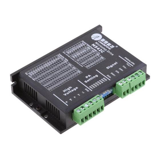
M542C
Full Digital Stepper Drive
Version 2.0
©2016 All Rights Reserved
Attention: Please read this manual carefully before using the drive!
11/F, Building A3, Nanshan ipark,NO.1001 Xueyuan Blvd, Nanshan Dist, Shenzhen, China
T: (86)755-26409254
F: (86)755-26402718
Web site:
www.leadshine.com
E-Mail:
sales@leadshine.com
Advertisement
Table of Contents

Related Manuals for Leadshine Technology M542C


Summary of Contents for Leadshine Technology M542C
- Page 1 User’s Manual M542C Full Digital Stepper Drive Version 2.0 ©2016 All Rights Reserved Attention: Please read this manual carefully before using the drive! 11/F, Building A3, Nanshan ipark,NO.1001 Xueyuan Blvd, Nanshan Dist, Shenzhen, China T: (86)755-26409254 F: (86)755-26402718 Web site: www.leadshine.com...
- Page 2 According to Leadshine’s terms and conditions of sales, the user of Leadshine’s products in life support or aircraft applications assumes all risks of such use and indemnifies Leadshine against all damages. ©2016 by Leadshine Technology Company Limited. All Rights Reserved...
-
Page 3: Table Of Contents
Contents Table of Contents 1 Introductions ................................1 1.1 Features ................................1 1.2 Applications ................................ 1 2. Specifications ................................1 2.1 Electrical Specifications ............................. 1 2.2 Operating Environment and other Specifications ....................2 2.3 Mechanical Specifications ..........................2 2.4 Elimination of Heating ............................2 3 Pin Assignment and Description .......................... -
Page 4: Introductions
M542C Full Digital Stepper Drive Manual V2.0 1 Introductions The M542C is a fully digital stepper drive developed with advanced DSP control algorithm based on the latest motion control technology. It has achieved a unique level of system smoothness, providing optimal torque and nulls mid-range instability. -
Page 5: Operating Environment And Other Specifications
3 Pin Assignment and Description The M542C has two connectors P1&P2, P1 is for control signals connections, and P2 is for power and motor connections. The following tables are brief descriptions of the two connectors. More detailed descriptions of the pins... -
Page 6: Connector P1 Configurations
4.1 Control Signal Connector (P1) Interface The M542C can accept differential and single-ended inputs (including open-collector and PNP output). The M542C has 3 optically isolated logic inputs which are located on connector P1 to accept line drive control signals. These inputs are isolated to minimize or eliminate electrical noises coupled with the drive control signals. -
Page 7: Connections Of 4-Lead Motor
M542C Full Digital Stepper Drive Manual V2.0 Figure 2: Connections to open-collector Figure 3: Connections to PNP signal (common-cathode) signal (common-anode) 4.2 Connections of 4-lead Motor The 4 lead motors are the least flexible and easy to connect. And the Speed – torque of motor depends on winding inductance. -
Page 8: Connections Of 8-Lead Motor
4.5 Power Supply Selection The M542C can match medium and small size stepping motors (frame size from NEMA 17 to 23) made by Leadshine or other motor manufactures around the world. To achieve good driving performances, it is important to select supply voltage and output current properly. -
Page 9: Multiple Drives
4.5.3 Selecting Supply Voltage The power MOSFETS inside the M542C can actually operate within +20~+50VDC, including power input fluctuation and back EMF voltage generated by motor coils during motor shaft deceleration. Higher supply voltage can increase motor torque at higher speeds, thus helpful for avoiding losing steps. -
Page 10: Current Settings
M542C Full Digital Stepper Drive Manual V2.0 Microstep Steps/rev.(for 1.8°motor) 1600 3200 6400 12800 25600 1000 2000 4000 5000 8000 10000 20000 25000 5.2 Current Settings For a given motor, higher drive current will make the motor to output more torque, but at the same time causes more heating in the motor and drive. -
Page 11: Standstill Current Setting
M542C Full Digital Stepper Drive Manual V2.0 5.2.2 Standstill Current Setting SW4 is used for this purpose. OFF meaning that the standstill current is set to be half of the selected dynamic current, and ON meaning that standstill current is set to be the same as the selected dynamic current. -
Page 12: Sequence Chart Of Control Signals
M542C Full Digital Stepper Drive Manual V2.0 7 Sequence Chart of Control Signals In order to avoid some fault operations and deviations, PUL, DIR and ENA should abide by some rules, shown as following diagram: Figure 10: Sequence chart of control signals Remark: t1: ENA must be ahead of DIR by at least 5s. -
Page 13: Frequently Asked Questions
M542C Full Digital Stepper Drive Manual V2.0 9 Frequently Asked Questions In the event that your drive doesn’t operate properly, the first step is to identify whether the problem is electrical or mechanical in nature. The next step is to isolate the system component that is causing the problem. As part of this process you may have to disconnect the individual components that make up your system and verify that they operate independently. -
Page 14: Appendix
Twelve Month Limited Warranty Leadshine Technology Co., Ltd. warrants its products against defects in materials and workmanship for a period of 12 months from shipment out of factory. During the warranty period, Leadshine will either, at its option, repair or replace products which proved to be defective. -
Page 15: Contact Us
M542C Full Digital Stepper Drive Manual V2.0 Contact Us China Headquarters Address: 11/F, Building A3 , Nanshan iPark, No.1001Xueyuan Blvd, Nanshan District Shenzhen, China http://www.leadshine.com Web: Sales Hot Line: Tel: 86-755-2643 4369 (for All) 86-755-2641-7674 (for Asia, Australia, Africa areas)
Need help?
Do you have a question about the M542C and is the answer not in the manual?
Questions and answers