Table of Contents
Advertisement
Quick Links
User Manual
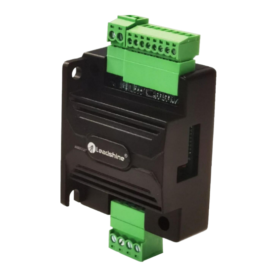
EM532MINI
Digital Microstep Drive
Revision 1.0
©2021 China Leadshine Technology Co., Ltd.
Address: 15-20/F, Block B, Nanshan I Valley, No.3185, Shahe West Road, Nanshan District,
Shenzhen, Guangdong, 518055, China
Tel: (86)755-26409254
Fax: (86)755-26402718
Web:
www.leadshine.com
Sales:
sales@leadshine.com
Support:
tech@leadshine.com
Advertisement
Table of Contents

Related Manuals for Leadshine Technology EM532MINI


Summary of Contents for Leadshine Technology EM532MINI
- Page 1 User Manual EM532MINI Digital Microstep Drive Revision 1.0 ©2021 China Leadshine Technology Co., Ltd. Address: 15-20/F, Block B, Nanshan I Valley, No.3185, Shahe West Road, Nanshan District, Shenzhen, Guangdong, 518055, China Tel: (86)755-26409254 Fax: (86)755-26402718 Web: www.leadshine.com Sales: sales@leadshine.com Support:...
- Page 2 EM532MINI Digital Stepper Drive User Manual Notice Read this manual carefully before any assembling and using. Incorrect handling of products in this manual can result in injury and damage to persons and machinery. Strictly adhere to the technical information regarding installation requirements.
-
Page 3: Table Of Contents
EM532MINI Digital Stepper Drive User Manual Table of Contents 1. Introductions................................... 1 1.1 Features...................................1 1.2 Applications................................1 2. Specifications...................................1 2.1 Electrical Specifications............................1 2.2 Environment................................2 2.3 Mechanical Specifications............................2 2.4 Elimination of Heat..............................2 3. Connection Pin Assignments and LED Indication...................... 3 3.1 P1 - Control Connector and Fault Output...................... -
Page 4: Introductions
& noise. Its operating voltage is 18-50VDC and it can output up to 3.2A current. All the micro step and output current are done via DIP switches. Therefore, the EM532MINI are ideal choices for applications requiring simple step &... -
Page 5: Environment
* Side mounting recommended for better heat dissipation 2.4 Elimination of Heat EM532MINI reliable working temperature should be < 60℃ (140°F) It is recommended to mount the drive vertically to maximize heat sink area. Use forced cooling method to cool if ... -
Page 6: Connection Pin Assignments And Led Indication
3. Connection Pin Assignments and LED Indication The EM532MINI has 3 terminal block connectors P1, P2 and P3, 1 DIP switch selectors S1. P1 is for control signal and fault output connections, P2 is for power connection, P3 is for motor connection. -
Page 7: P3 - Motor Connector
3.4 Indicator Light There are two lights for EM532MINI. The GREEN one is the power indicator which will be always on generally. The RED one is a protection indicator which will flash 1-2 times in a 3-second period, when protection enabled for a EM532MINI. -
Page 8: Motor Connection
Figure 5 Fault Output Connections 5. Motor Connection The EM532MINI can drive 2-phase and 4-pahse bipolar hybrid stepper motors with 4, 6, or 8 wires. 5.1 Connections of 4-lead Motor The 4 lead motors are the least flexible and easy to connect. And the Speed – torque of motor depends on winding inductance. -
Page 9: Full Coil Configuration
EM532MINI Digital Stepper Drive User Manual Figure 7: 6-lead motor half coil (higher speed) connections 5.2.2 Full Coil Configuration The full coil configuration on a six lead motor should be used in applications where higher torque at lower speed is desired. -
Page 10: Power Supply Selection
6. Power Supply Selection The EM532MINI can power medium and small size stepping motors (frame size from NEMA11 to 17) made by Leadshine or other motor manufacturers. To get good driving performances, it is important to select supply voltage and output current properly. -
Page 11: Dip Switch Configurations
(SW1-3) The EM532MINI has 8 output current settings which can be configured through DIP switch SW1, SW2 and SW3. For a given stepper motor, as normal setting the output current to 1.4 times of motor phase current, will make it output larger torque, but at the same time cause more heating for both the motor and drive. -
Page 12: Wiring Notes
It is better to separate them by 10 cm at least, otherwise the disturbing signals generated by motor will easily disturb pulse direction signals, causing motor position error, system instability and other failures. If only one power supply serves multiple EM532MINI drives, separately connecting the drives to the power ... -
Page 13: Sequence Chart Of Control Signals
EM532MINI Digital Stepper Drive User Manual Figure 11: Typical connection 10. Sequence Chart of Control Signals In order to avoid some fault operations and deviations, PUL, DIR and ENA should abide by some rules, shown as following diagram: Figure 12: Sequence chart of control signals Remark: t1: ENA must be ahead of DIR by 200ms at least. -
Page 14: Protection Functions
EM532MINI Digital Stepper Drive User Manual 11. Protection Functions To improve reliability, the drive incorporates some built-in protections features. Time(s) of Priority Sequence wave of red LED Description Blink Always on The drive was short-circuited or burned out. Over-current protection activated when peak current exceeds the limit. -
Page 15: Troubleshooting
EM532MINI Digital Stepper Drive User Manual 12. Troubleshooting In the event that your drive doesn’t operate properly, the first step is to identify whether the problem is electrical or mechanical in nature. The next step is to isolate the system component that is causing the problem. As part of this process you may have to disconnect the individual components that make up your system and verify that they operate independently. -
Page 16: Warranty
Twelve Month Warranty Leadshine Technology Co., Ltd. warrants its products against defects in materials and workmanship for a period of 12 months from shipment out of factory. During the warranty period, Leadshine will either, at its option, repair or replace products which proved to be defective. - Page 17 EM532MINI Digital Stepper Drive User Manual Web: http://www.leadshineusa.com Email: sales@leadshineusa.com and support@leadshineusa.com. Page | 14...
Need help?
Do you have a question about the EM532MINI and is the answer not in the manual?
Questions and answers