Table of Contents
Advertisement
Quick Links
The content in this manual has been carefully prepared and is believed to be accurate, but no
responsibility is assumed for inaccuracies.
Leadshine reserves the right to make changes without further notice to any products herein to
User's Manual
improve reliability, function or design. Leadshine does not assume any liability arising out of the
For
application or use of any product or circuit described herein; neither does it convey any license
M542 V2.0
under its patent rights of others.
Leadshine's general policy does not recommend the use of its products in life support or aircraft
applications wherein a failure or malfunction of the product may directly threaten life or injury.
High Performance Microstepping Driver
According to Leadshine's terms and conditions of sales, the user of Leadshine's products in life
support or aircraft applications assumes all risks of such use and indemnifies Leadshine against all
Version 1.0
damages.
©2008 All Rights Reserved
Attention: Please read this manual carefully before using the driver!
©2008 by Leadshine Technology Company Limited.
All Rights Reserved
DOLD Mechatronik
info@dold-mechatronik.de
Sarach 10 – D-77790 Steinach
www.dold-mechatronik.de
Telefon: +49 7832 / 9744670
Advertisement
Table of Contents

Subscribe to Our Youtube Channel
Related Manuals for Leadshine Technology M542 V2.0


Summary of Contents for Leadshine Technology M542 V2.0
- Page 1 Leadshine against all Version 1.0 damages. ©2008 All Rights Reserved Attention: Please read this manual carefully before using the driver! ©2008 by Leadshine Technology Company Limited. All Rights Reserved DOLD Mechatronik info@dold-mechatronik.de Sarach 10 – D-77790 Steinach www.dold-mechatronik.de...
-
Page 2: Table Of Contents
Contents Contents Dynamic current setting ................9 Table of Contents Standstill current setting................9 1. Introduction, Features and Applications..............1 8. Wiring Notes ......................10 Introduction ......................1 9. Typical Connection....................10 Features ......................... 1 10. Sequence Chart of Control Signals ............... 11 Applications ...................... -
Page 3: Introduction, Features And Applications
Introduction Avoid dust, oil fog and corrosive gases Environment The M542 V2.0 is a high performance microstepping driver based on pure-sinusoidal current 0 ℃ - 50℃ Ambient Temperature control technology. Owing to the above technology and the self-adjustment technology (self-adjust 40%RH -... -
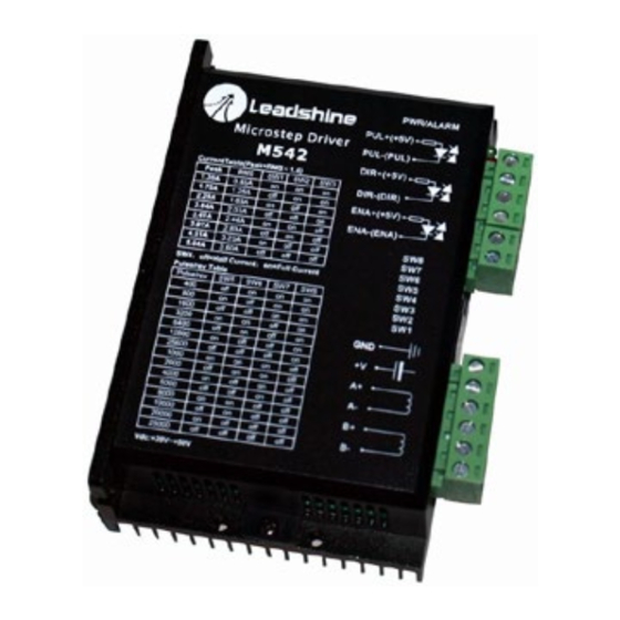
Page 4: Pin Assignment And Description
J3), this signal is counter-clock (CCW) pulse,active at high output). The M542 V2.0 has 3 optically isolated logic inputs which are located on connector P1 to level or low level (set by inside jumper J1, J2). For reliable motion response, accept line driver control signals. -
Page 5: Connecting The Motor
5. Connecting the Motor motors should be run at only 70% of their rated current to prevent over heating. The M542 V2.0 can drive any 2-phase and 4-phase hybrid stepping motors. Connections to 4-lead Motors 4 lead motors are the least flexible but easiest to wire. Speed and torque will depend on winding Figure 7: 6-lead motor full coil (higher torque) connections inductance. -
Page 6: Parallel Connections
7. Selecting Microstep Resolution and Driver Output Current The M542 V2.0 can match medium and small size stepping motors (from NEMA frame size 17 to 34) made by Leadshine or other motor manufactures around the world. To achieve good driving This driver uses an 8-bit DIP switch to set microstep resolution, and motor operating current, as performances, it is important to select supply voltage and output current properly. -
Page 7: Current Settings
M542 V2.0 Microstepping Driver Manual V1.0 M542 V2.0 Microstepping Driver Manual V1.0 The current automatically reduced to 60% of the selected dynamic current one second after the last 4000 pulse. Theoretically, this will reduce motor heating to 36% (due to P=I *R) of the original value. - Page 8 M542 V2.0 Microstepping Driver Manual V1.0 M542 V2.0 Microstepping Driver Manual V1.0 10. Sequence Chart of Control Signals Over-current Protection In order to avoid some fault operations and deviations, PUL, DIR and ENA should abide by some Protection will be activated when continuous current reaches to 16A.
- Page 9 M542 V2.0 Microstepping Driver Manual V1.0 Problem Symptoms and Possible Causes Symptoms Possible Problems No power Microstep resolution setting is wrong Motor is not rotating DIP switch current setting is wrong Fault condition exists The driver is disabled Motor phases may be connected in reverse...
Need help?
Do you have a question about the M542 V2.0 and is the answer not in the manual?
Questions and answers