Fluidwell F Series Manual
Ratio indicator and monitor with totalizer / flowrate indication
Hide thumbs
Also See for F Series:
- Manual (64 pages) ,
- User manual (60 pages) ,
- Operation manual (60 pages)
Table of Contents
Advertisement
Quick Links
F114-A
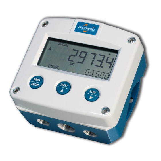
RATIO INDICATOR AND MONITOR
WITH TOTALIZER / FLOWRATE INDICATION
Signal input flowmeters: (0)4-20mA
Signal outputs: 4-20mA ref. ratio or flowrate
Alarm outputs: maximum four ratio alarms
Options: Intrinsically Safe, Modbus communication
F-Series - Field mounted indicators for safe and hazardous areas. More info: www.fluidwell.com/fseries
Advertisement
Table of Contents

Related Manuals for Fluidwell F Series


Summary of Contents for Fluidwell F Series
- Page 1 WITH TOTALIZER / FLOWRATE INDICATION Signal input flowmeters: (0)4-20mA Signal outputs: 4-20mA ref. ratio or flowrate Alarm outputs: maximum four ratio alarms Options: Intrinsically Safe, Modbus communication F-Series - Field mounted indicators for safe and hazardous areas. More info: www.fluidwell.com/fseries...
-
Page 2: Safety Instructions
Intrinsically Safe applications: follow the instructions as mentioned in Chapter 5 and consult “Fluidwell F1..-..-XI - Documentation for Intrinsic Safety”. DISPOSAL At the end of its life this product should be disposed of according to local regulations regarding waste electronic equipment. - Page 3 Manual HF114AEN_v0501_04 © Copyright 2011 Fluidwell bv - The Netherlands. Information in this manual is subject to change without prior notice. The manufacturer is not responsible for mistakes in this material or for incidental damage caused as a direct or indirect result of the delivery, performance or use of this material.
-
Page 4: Table Of Contents
Page 4 Contents manual Safety instructions ............................2 Safety rules and precautionary measures ....................... 2 Introduction ..........................5 1.1. System description of the F114-A ..................5 Operational ..........................7 2.1. General ..........................7 2.2. Control panel .......................... 7 2.3. Operator information and functions ..................8 Configuration .......................... -
Page 5: Introduction
Page 5 INTRODUCTION 1.1. SYSTEM DESCRIPTION OF THE F114-A Functions and features The ratio indicator / monitor model F114-A is a microprocessor driven instrument designed to calculate, display and monitor the ratio between two flows as well as the flowrates and totals. This product has been designed with a focus on: ... - Page 6 Page 6 Configuration of the unit The F114-A was designed to be implemented in many types of applications. For that reason, a SETUP-level is available to configure your F114-A according to your specific requirements. SETUP includes several important features, such as Span, measurement units etc. All setting are stored in EEPROM memory and will not be lost in the event of power failure or a drained battery.
-
Page 7: Operational
Page 7 OPERATIONAL 2.1. GENERAL The F114-A may only be operated by personnel who are authorized and trained by the operator of the facility. All instructions in this manual are to be observed. Take careful notice of the " Safety rules, instructions and precautionary measures " in the front of this manual. -
Page 8: Operator Information And Functions
Page 8 2.3. OPERATOR INFORMATION AND FUNCTIONS In general, the F114-A will always function at Operator level. The information displayed is dependant upon the SETUP-settings. All pulses generated by the connected flowmeter are measured by the F114-A in the background, whichever screen refresh rate setting is chosen. After pressing a key, the display will be updated very quickly during a 30 second period, after which it will slow-down again. - Page 9 Page 9 When data is altered but ENTER has not been pressed yet, then the alteration can still be cancelled by waiting for 20 seconds or by pressing ENTER during three seconds: the former value will be reinstated. Ratio alarm ...
-
Page 10: Configuration
Page 10 CONFIGURATION 3.1. INTRODUCTION This and the following chapters are exclusively meant for electricians and non-operators. In these, an extensive description of all software settings and hardware connections are provided. Mounting, electrical installation, start-up and maintenance of the instrument may only be carried out by trained personnel authorized by the operator of the facility. - Page 11 Page 11 Matrix structure SETUP-level: SCROLLING THROUGH SETUP-LEVEL Selection of function-group and function: SETUP is divided into several function groups and functions. Each function has a unique number, which is displayed below the word "SETUP" at the bottom of the display. The number is a combination of two figures. The first figure indicates the function-group and the second figure the sub-function.
- Page 12 Page 12 To change or select a value: To change a value, use to select the digits and to increase that value. To select a setting, both and can be used. If the new value is invalid, the increase sign or decrease-sign will be displayed while you are programming.
-
Page 13: Overview Functions Setup Level
Page 13 3.2.2. OVERVIEW FUNCTIONS SETUP LEVEL SETUP FUNCTIONS AND VARIABLES TOTAL A UNIT L - m3 - kg - lb - GAL - USGAL - bbl - no unit DECIMALS 0 - 1 - 2 - 3 (Ref: displayed value) SPAN 0.000001 - 999,999 unit/second DECIMALS SPAN... -
Page 14: Explanation Of Setup-Functions
Page 14 RELAYS RELAY 1 off, lo-lo, lo, hi, hi-hi, all RELAY 2 off, lo-lo, lo, hi, hi-hi, all RELAY 3 off, lo-lo, lo, hi, hi-hi, all RELAY 4 off, lo-lo, lo, hi, hi-hi, all COMMUNICATION SPEED / BAUDRATE 1200 - 2400 - 4800 - 9600 ADDRESS 1 - 255 MODE... -
Page 15: Flowrate A
Page 15 DECIMALS SPAN This setting determines the number of decimals for the Span (SETUP 13). The following can be selected: 0 - 1 - 2 - 3 - 4 - 5 - 6 Please note that this function influences the accuracy of the Span indirectly. -
Page 16: Total B
Page 16 3 - TOTAL B SPAN With the span, the flowmeter signal is converted to a quantity. The span for Total is determined on the basis of the measurement unit (setting 11) and the flowrate per second at 20mA. Enter the span in whole numbers (decimals are set with SETUP 14). -
Page 17: Ratio
Page 17 5 - RATIO FORMULA The definition of the ratio displayed is set with this function. The ratio can be expressed as: 1) the flowrate of the "additive flow" compared to the flowrate of the "main flow", or as 2) the flowrate of the "additive flow"... -
Page 18: Alarm
Page 18 6 - ALARM With these settings, it is determined how the ratio will be. Note: for alarm relay output functions: read SETUP A “relays”. FLOW ZERO When the flowrate of BOTH flows is zero, then it is possible to ignore or disable the ratio monitoring. -
Page 19: Power Management
Page 19 8 - POWER MANAGEMENT When used with the internal battery option, the user can expect reliable measurement over a long period of time. The F114-A has several smart power management functions to extend the battery life time significantly. Two of these functions can be set: LCD NEW The calculation of the display-information influences the power consumption significantly. -
Page 20: Flowmeter A
Page 20 9 - FLOWMETER A SIGNAL The F114-A can process the 4-20mA signal in two ways: Interpolation: the signal is processed linear R = S x I Square root: for differential pressure √ R = S where: R = Rate: the calculated flowrate S = Span: the maximum flowrate at 20mA. - Page 21 Page 21 9 - FLOWMETER A (CONTINUED) CUT-OFF To ignore e.g. leakage of the flow or vibration, a low-flow cut-off can be set as percentage over the full range of 16mA (or 20mA / 10V). When the analog value is less then required with this setting, the signal will be ignored.
-
Page 22: A - Flowmeter B
Page 22 A - FLOWMETER B SIGNAL The F114-A can process the 4-20mA signal in two ways: Interpolation: the signal is processed linear Square root: for differential pressure For explanation of this function: please read “9 - Flowmeter A” FILTER With the help of this digital filter a stable and accurate reading can be obtained while the filter level can be set to a desired value. -
Page 23: B - Analog Output
Page 23 B - ANALOG OUTPUT A linear (0)4-20mA or 0-10V output signal is generated according to the calculated ratio, flowrate A or flowrate B with a 10 bits resolution. The settings for ratio (SETUP 52) and flowrate (SETUP - 2) directly influence the analog output. -
Page 24: C - Relay Output
Page 24 C - RELAY OUTPUT With “SETUP 6”, four alarm levels can be entered. Based on the options ordered, the F114-A will have 2, 3 or 4 alarm outputs. Note: If the unit is Intrinsically Safe, it will have two alarm outputs. If option OS (relay board) has been supplied, it will have four alarm outputs. -
Page 25: Installation
Page 25 INSTALLATION 4.1. GENERAL DIRECTIONS Mounting, electrical installation, start-up and maintenance of this instrument may only be carried out by trained personnel authorized by the operator of the facility. Personnel must read and understand this Operating Manual before carrying out its instructions. ... -
Page 26: Dimensions- Enclosure
Page 26 4.3. DIMENSIONS- ENCLOSURE Aluminum enclosures: 75 mm (2.95") 112 mm (4.40") 130 mm (5.12") 12mm 12mm 30mm 30mm 24mm 24mm M20 x 1,5 6 x M12 36mm 36mm 30mm 30mm M16 x 1,5 M16 x 1,5 1/2"NPT M20 x 1,5 0.12"... - Page 27 Page 27 GRP enclosures: 75 mm (2.95") 112 mm (4.40") 130 mm (5.12") HK back box: (flat bottom) 75 mm (2.95") 118 mm (4.65”) 25mm 25mm D=20mm D=20mm 12mm 12mm 30mm 30mm 24mm 24mm D=12mm D=16mm D=16mm D=20mm 36mm 36mm 0.12”...
-
Page 28: Installing The Hardware
Page 28 4.4. INSTALLING THE HARDWARE 4.4.1. INTRODUCTION Electro static discharge does inflict irreparable damage to electronics! Before installing or opening the unit, the installer has to discharge himself by touching a well-grounded object. This unit must be installed in accordance with the EMC guidelines (Electro Magnetic Compatibility). -
Page 29: Voltage Selection Sensor Supply
Page 29 4.4.2. VOLTAGE SELECTION SENSOR SUPPLY For Intrinsically Safe applications: read chapter 5. Type PB / PC / PX (AP) - battery powered and output loop-powered applications: Terminal 11 provides a limited supply voltage of 3.2 V DC (coil signals 1.2V) for the signal output of the flowmeter. -
Page 30: Terminal Connectors
Page 30 4.4.3. TERMINAL CONNECTORS For Intrinsically Safe applications: read chapter 5. The following terminal connectors are available: ANALOG OUTPUT ALARM ALARM TYPE AA / AB ALARM OPTION: OUTPUT R2 OUTPUT R1 AI / AP / AU SENSOR A SENSOR B OUTPUT R3 POWER SUPPLY: TYPE... - Page 31 Page 31 Terminal 03-04; alarm output R2: This output is an alarm output according setup B2. Terminal 05-06; alarm output R1: This output is an alarm output according setup B1. Type OA: An active 24V DC signal ratio alarm output is available with this option. Max.
- Page 32 Page 32 Type OT: A passive transistor output is available with this option. Max. driving capacity 300mA@50V DC. Terminal 07-08; basic POWER SUPPLY - type PX - output loop powered: Connect an external power supply of 8-30VDC to these terminals or a 4-20mA loop. Do connect the "-"...
- Page 33 Page 33 Type AB: An active 0-20mA signal proportional to the ratio or flowrate is available with this option. Max. driving capacity 1000 Ohm @ 24VDC. (Requires power supply type PD / PF / PM). Type AF: For the Intrinsically Safe floating 4-20mA signal: please read Chapter 5. Type AI: An isolated 4-20mA signal proportional to the ratio or flowrate is available with this option.
- Page 34 Page 34 Type AU: A 0-10VDC signal proportional to the ratio or flowrate is available with this option. Max. load 10mA @ 10VDC. (Requires power supply type PD / PF / PM). Terminal 09-11: Type A – Flowmeter input (general) The F111-A requires a (0)4-20mA flowmeter signal which will be processed 4 times a second with a 14 bits accuracy.
- Page 35 Page 35 Terminal 12-14; Flowmeter input B: The F114-A requires a (0)4-20mA flowmeter signal which will be processed 4 times a second with a 14 bits accuracy. The input is not isolated. For Intrinsically safe applications: please read chapter 5. (0)4 - 20mA signal input INTERNAL EXTERNAL...
- Page 36 Page 36 Terminal 26-31: type CB / CH / CI / CT - communication RS232 / RS485 / TTL (option) Full serial communications and computer control in accordance with RS232 (length of cable max. 15 meters) or RS485 (length of cable max. 1200 meters) is possible. ...
-
Page 37: Intrinsically Safe Applications
Please Note Certificates, safety values and declaration of compliance can be found in the document named: “Fluidwell F1..-..-XI - Documentation for Intrinsic Safety”. Special conditions for safe use mentioned in both the certificate and the installation instructions must be observed for the connection of power to both input and / or output circuits. -
Page 38: Terminal Connectors Intrinsically Safe Applications
Indicated labels on the back cover (below) and on the inside cover (right) show the type labels for intrinsically safe certified units. For details on usage see the separate “Fluidwell F1..-..-XI Documentation for Intrinsic Safety”. Serial number and year of production This information can be looked-up on the display: See setup function (par. - Page 39 Page 39 Explanation Intrinsically Safe options: Option AF - Intrinsically Safe floating 4-20mA analog output: A floating 4-20mA signal proportional to the flowrate is available with this option. When the output is disabled, a 3.5mA signal will be generated. Max. driving capacity 1000 Ohm @ 30V DC. Note! It is required to link the minus from the analog output - terminal 7 - with a ground terminal of the unit, e.g.
-
Page 40: Configuration Examples Intrinsically Safe Applications
Page 40 5.3. CONFIGURATION EXAMPLES INTRINSICALLY SAFE APPLICATIONS Configuration example IIB /IIIC F114-A-AP-CT-OT-XI HAZARDOUS AREA SAFE AREA TERMINAL CONNECTORS F100-series Modbus communication type CT: TTL I.S. Certified Isolator TTL to: = max. 30 V e.g. PC RS232 = max. 250 mA RS422 = max. - Page 41 Page 41 Configuration example IIB/IIIC and IIC - F114-A-AP-(CT)-OT-PD-XI HAZARDOUS AREA SAFE AREA TERMINAL CONNECTORS F100-series Modbus communication type CT: TTL Please note: communciation type CT is allowed in IIC applications. I.S. Certified Isolator TTL to: = max. 30 V e.g.
-
Page 42: Battery Replacement Instructions
Batteries for use in safe areas have no Ex label. DO NOT EXCHANGE: Using the wrong type of battery can pose a SERIOUS RISK. For use in hazardous areas Fluidwell recommends FW-LiBAT type batteries (manufactured by Fluidwell bv) only. Battery replacement procedure Depending on the production batch, one of two visualized Intrinsically Safe certified battery types may have been installed in the unit. -
Page 43: Maintenance
Page 43 MAINTENANCE 6.1. GENERAL DIRECTIONS Mounting, electrical installation, start-up and maintenance of the instrument may only be carried out by trained personnel authorized by the operator of the facility. Personnel must read and understand this Operating Manual before carrying out its instructions. ... -
Page 44: Appendix A: Technical Specification
Page 44 APPENDIX A: TECHNICAL SPECIFICATION GENERAL Display Type High intensity reflective numeric and alphanumeric LCD, UV-resistant. Digits Seven 17mm (0.67") and eleven 8mm (0.31"). Various symbols and measuring units. Refresh rate User definable: 8 times/sec - 30 secs. Type ZB Transflective LCD with green LED backlight. - Page 45 Page 45 Sensor excitation Type PB / PC / PX 3.2V DC for pulse signals and 1.2V DC for coil pick-up. Note: This is not a real sensor supply. Only suitable for pulse sensors with a very low power consumption like coils (sine wave) and reed-switches. Type PD 1.2 - 3.2 - 8.2 - 12 and 24V DC - max.
- Page 46 Page 46 OUTPUTS Analog output Function transmitting ratio, flowrate A or flowrate B. Resolution 10-bit. Accuracy error < 0.05% - update 10 times a second. Software function to calibrate the (0)4.00mA and 20.00mA / 0 and 10V levels precisely. Load max.
- Page 47 Page 47 OPERATIONAL Operator functions Displayed functions • ratio 1:__ or as %. • total A (this function can be disabled). • flowrate A (this function can be disabled). • total B (this function can be disabled). • flowrate B (this function can be disabled). •...
-
Page 48: Appendix B: Problem Solving
Page 48 APPENDIX B: PROBLEM SOLVING In this appendix, several problems are included that can occur when the F114-A is going to be installed or while it is in operation. Analog output does not function properly: Check: SETUP B1 - is the function enabled? ... -
Page 49: Appendix C: Communication Variables
Page 49 APPENDIX C: COMMUNICATION VARIABLES Not fully implemented yet. Remarks: Below, an overview of the F114-A specific variables; other common variables are described in the standard table. All numbers are decimal numbers, unless otherwise noted. The following variables of the standard table (var00-var30) are not valid for this product and will be responded with value 1: var00, 03-05, 07,08, 16-22, 24, 26-29. - Page 50 Page 50 DESCRIPTION BYTES VALUE REMARKS TOTAL B span 1..9.999.999 S 0000001 up to S 0000009 is (28h) allowed when decs < 6! (VAR37) decimals Span 0…6 (2Bh) FLOWRATE B span 1..9.999.999 S 0000001 up to S 0000009 is (E3h) allowed when decs <...
- Page 51 Page 51 DESCRIPTION BYTES VALUE REMARKS ANALOG OUTPUT analog output 0=disable (70h) 1=enable minimum rate 0..9999999 unit, time, decimals acc. var48-50 (71h) maximum rate 0..9999999 unit, time, decimals acc. var48-50 (74h) cut off percentage 0..99 steps of 0.1% (77h) tune minimum rate 0..9999 (78h) tune maximum rate...
- Page 52 Page 52 INDEX OF THIS MANUAL actual settings ........54, 55 Installation ............ 25 alarm Intrinsic safety ..........37 delay time ..........18 Intrinsically Safe options ......39 flow zero ............ 18 IP classification ..........25 high alarm..........8, 18 keys ...............
- Page 53 Page 53 NOTES HF114AEN_v0501_04...
- Page 54 Page 54 Left blank intentionally HF114AEN_v0501_04...
- Page 55 Page 55 LIST OF CONFIGURATION SETTINGS SETTING DEFAULT DATE : DATE : 1 - TOTAL A Enter your settings here 11 unit 12 decimals 0000000 13 span /sec /sec 000001 /sec 14 decimals span 2 - FLOWRATE A 21 unit 22 time unit /min 23 decimals...
- Page 56 E - OTHERS E4 pass code 0000 E5 tagnumber 0000000 Fluidwell bv HF114AEN_v0501_04 PO box 6 Voltaweg 23 Website: www.fluidwell.com 5460 AA Veghel 5466 AZ Veghel Find your nearest representative: www.fluidwell.com/representatives The Netherlands The Netherlands Copyright Fluidwell bv - 2012 - HF110AEN_v0501_03...
Need help?
Do you have a question about the F Series and is the answer not in the manual?
Questions and answers