Table of Contents
Advertisement
Quick Links
To learn more about EMAC's products and services and how they can help your project
http://ftp.emacinc.com/Tech_Info/About_EMAC_Products_and_Services.pdf
Authorized Distributor, Integrator, and Value-Added Reseller
Manual downloaded from
ftp.emacinc.com
For purchase information please contact
info@emacinc.com
For technical support please submit a ticket at
www.emacinc.com/support
Advertisement
Table of Contents

Related Manuals for Advantech MIO-2270


Summary of Contents for Advantech MIO-2270
- Page 1 To learn more about EMAC’s products and services and how they can help your project http://ftp.emacinc.com/Tech_Info/About_EMAC_Products_and_Services.pdf Authorized Distributor, Integrator, and Value-Added Reseller Manual downloaded from ftp.emacinc.com For purchase information please contact info@emacinc.com For technical support please submit a ticket at www.emacinc.com/support...
- Page 2 User Manual MIO-2270 AMD® G-series SoC GX-210JA/ GX-415GA Pico-ITX SBC, DDR 3/ 3L, 18-bit LVDS, VGA or HDMI, 1GbE, Half-size Mini PCIe, 4 USB, 2 COM, SMBus, mSATA, and MIOe...
- Page 3 No part of this manual may be reproduced, copied, translated or transmitted in any form or by any means without prior written permission from Advantech Co., Ltd. The information provided in this manual is intended to be accurate and reliable. However, Advantech Co., Ltd.
- Page 4 Because of Advantech’s high quality-control standards and rigorous testing, most of our customers never need to use our repair service. If an Advantech product is defec- tive, it will be repaired or replaced at no charge during the warranty period. For out- of-warranty repairs, customers are billed according to the cost of replacement materi- als, service time and freight.
- Page 5 Mini PCIe, 4 USB, 2 COM, SMBus, mSATA, and MIOe AMD® G-series SoC GX-415GA, cooler, LVDS, HDMI, GbE, MIO-2270QH-S5A1E Mini PCIe, 4 USB, 2 COM, SMBus, mSATA, and MIOe Optional Accessories Part No. Description 1960065075N001 Heat spreader (99.5 x 70.5 x 11.2 mm) MIO-2270 User Manual...
- Page 6 Caution! New batteries are at risk of exploding if incorrectly installed. Do not attempt to recharge, force open, or heat the battery. Replace the battery only with the same or equivalent type recommended by the manufac- turer. Discard used batteries according to the manufacturer's instruc- tions. MIO-2270 User Manual...
- Page 7 The sound pressure level at the operator’s position does not exceed 70 dB (A), as per the IEC 704-1:1982 specifications. DISCLAIMER: These instructions are provided according to the IEC 704-1 standard. Advantech disclaims all responsibility for the accuracy of the statements contained herein. MIO-2270 User Manual...
- Page 8 Do not touch components on the CPU card or other cards when the PC is powered on. Disconnect the power supply before implementing configuration changes. A sudden rush of power after connecting a jumper or installing a card may dam- age sensitive electronic components. MIO-2270 User Manual...
- Page 9 MIO-2270 User Manual viii...
-
Page 10: Table Of Contents
BIOS Setup ..................... 20 Entering the Setup Menu ................ 21 3.2.1 Main Setup Menu................ 21 3.2.2 Advanced BIOS Features ............22 3.2.3 Chipset Configuration ..............33 3.2.4 Boot Configuration ..............38 3.2.5 Security Configuration..............39 3.2.6 Save and Exit................40 MIO-2270 User Manual... - Page 11 System Assignments......79 System I/O Ports..................80 Table C.1: System I/O Ports ............80 First MB Memory Map................80 Table C.2: First MB Memory Map ..........80 Interrupt Assignments ................81 Table C.3: Interrupt Assignments ..........81 MIO-2270 User Manual...
-
Page 12: Chapter 1 General Introduction
Chapter General Introduction This chapter provides general information about MIO-2270. Introduction Product Features Specifications... -
Page 13: Introduction
SoC dual-core GX-210JA 1.0 GHz and quad-core GX-415GA 1.5 GHz proces- sors. MIO-2270 supports up to 8 GB of DDR3 or DDR3L memory, features two USB 2.0 and two USB 3.0-compatible ports, one GbE (up to 1000 Mbps) interface, LVDS and VGA or HDMI support, high definition (HD) audio, and one half-size mini-PCIe and MIOe expansion slot. -
Page 14: Functional Specifications
Lanes 3 & 4: MIOe connector 1 x mSATA by Mini-PCIe socket (integrates USB signals, and supports either mSATA or USB interface modules) SATA Interface 1 x SATAIII (600 MB/s maximum data transfer rate) MIO-2270 User Manual... -
Page 15: Mechanical Specifications
L100 mm x W72 mm (3.9" x 2.8") 1.2.3.2 Height of Component Side (mm) 15.7 mm (heat sink) 1.2.3.3 Height of Solder Side (mm) 16.4 mm (rear I/O USB) 1.2.3.4 Weight (g) 420 g (0.93 lb, total package weight) MIO-2270 User Manual... -
Page 16: Electrical Specifications
40 °C @ 95% RH non-condensing 1.2.5.2 Operating Temperature 0 ~ 60 °C (32 ~ 140 °F) 1.2.5.3 Storage Humidity 60 °C @ 95% RH non-condensing 1.2.5.4 Storage Temperature -40 ~ 85 °C (-40 ~ 185 °F) MIO-2270 User Manual... -
Page 17: Block Diagram
Realtek ALC888S HD Audio 12 Vsb / 5 Vsb Reset SMBus Line-in, Line-out Realtek GbE RJ45 PCIe x1 2 x USB2.0 USB2.0 RTL8111E-GR COM1: RS-232/422/485 COM2: RS-232 Super I/O 8-bit GPIO Watchdog Timer Figure 1.1 Block diagram MIO-2270 User Manual... -
Page 18: Chapter 2 H/W Installation
Chapter H/W Installation This chapter provides informa- tion on the hardware setup proce- dures, including instructions for connecting jumpers, peripherals, switches, and indicators, as well as mechanical drawings. Please read all safety precautions before beginning installation. -
Page 19: Jumpers
Table 2.2: J1: LCD Power / Auto Power On Part No. 1653003260 Footprint HD_3x2P_79 Description Pin header 3*2P 180D(M) 2.0 mm SMD square pin Setting Function (1-2) +5 V (3-4) (default) +3.3 V (5-6) (default) Auto power on MIO-2270 User Manual... - Page 20 DDR3L (2-3)* DDR3 *default LAN Enable / Disable Part No. 1600000071 Footprint SW_3P_CJS-1201TA1 Description DIP SW CJS-1201TA1 SMD 3P SPDT P = 6.0 mm W = 2.5 mm Setting Function (1-2)* LAN Enable (2-3) LAN Disable *default MIO-2270 User Manual...
-
Page 21: Connectors
2.2.2.3 Display Interface Connections (CN3, CN15, and CN20) The MIO-2270 display interface supports either VGA or HDMI on rear I/O and is capable of driving a wide range of flat panel displays, including passive and active LCD displays.The board features three display connector types; among which, one rear I/O can accommodate either standard CRT VGA monitors or an HDMI display and one supports LVDS-type LCD panels. - Page 22 2.2.2.8 COM Port Connectors (CN12) MIO-2270 features one RS-232 and one RS-232 / 422 / 485 serial ports in a 10 x 2- pin header. This provides connections for serial devices or a communication network. The pin assignments for the COM port connector are presented as Appendix A.
- Page 23 SMBus proto- cols, facilitating multiple simultaneous device control. 2.2.2.17 Battery Connector (BH1) MIO-2270 supports a 3 V / 210 mAH CR2032 lithium battery with wire via a battery connector (BH1). Note! To clear the CMOS, please follow the steps below.
-
Page 24: Mechanical
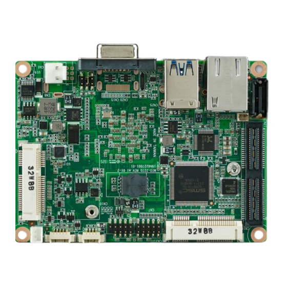
Mechanical 2.3.1 Jumper and Connector Locations CN15 CN14 CN12 Figure 2.1 Jumper and connector layout (top side) CN15 CN25 CN17 CN21 CN16 CN10 CN18 CN6 CN22 CN24 CN7 CN31 Figure 2.2 Jumper and connector layout (bottom side) MIO-2270 User Manual... -
Page 25: Board Dimensions
34.10 28.99 25.81 3.25 3.25 Unit: mm Figure 2.3 Board dimensions and layout (top side) 69,33 68.75 68.75 62.17 35.70 15.62 13.04 6.83 10.91 3.63 3.25 3.25 Unit: mm Figure 2.4 Board dimensions and layout (bottom side) MIO-2270 User Manual... - Page 26 104.36 46.23 16.51 40.96 65.41 83.31 97.15 Unit: mm Figure 2.5 Board dimensions and layout (side view) 104.36 46.23 17.27 40.96 65.41 83.31 97.15 Unit: mm Figure 2.6 Board dimensions and layout (coastline with optional DC jack) MIO-2270 User Manual...
- Page 27 40.96 65.41 83.31 97.15 Unit: mm Figure 2.8 Board dimensions and layout (coastline with power connector and optional heat spreader) 104.36 16.51 40.96 65.41 83.31 97.15 Unit: mm Figure 2.9 Board dimensions and layout (coastline with cooler) MIO-2270 User Manual...
- Page 28 MIOe connector is 16 mm (a height of 19 mm is also avail- able upon request). The height of the MIO-2270 power connector (including the cable) should be considered when assembling the system or stacking the MI/O module.
- Page 29 2.3.2.3 Another Thermal Solution - Heat Spreader MIO-2270 can accommodate an optional heat spreader for a more comprehensive compact system. Conducting heat to the chassis using a heat spreader is extremely beneficial when systems are extra compact or have limited space for heat convec- tion.
-
Page 30: Chapter 3 Bios Settings
Chapter BIOS Settings... -
Page 31: Bios Setup
AMI's BIOS ROM has a built-in setup program that allows users to modify the basic system configuration. This information is then stored in flash ROM to ensure that the setup information is retained even when the system is powered off. MIO-2270 User Manual... -
Page 32: Entering The Setup Menu
System Date using the <Arrow> keys. Enter new values using the keyboard. Press the <Tab> or <Arrow> keys to move between fields. The date must be entered in MM/DD/YY format. The time must be entered in HH:MM:SS format. MIO-2270 User Manual... -
Page 33: Advanced Bios Features
Advanced BIOS setup options by highlighting various items using the <Arrow> keys. All Advanced BIOS setup options are described in this section. The Advanced BIOS setup screens are shown below, and the submenus are described in subsequent sec- tions. MIO-2270 User Manual... - Page 34 This item allows users to enable or disable PCI device PERR# generation. SERR# Generation This item allows users to enable or disable PCI device SERR# generation. PCI Express Settings This item allows users to configure the PCI Express device settings. MIO-2270 User Manual...
- Page 35 This item allows users to enable or disable BIOS ACPI auto configuration. Enable Hibernation This item allows users to enable or disable the hibernation function (if supported by the OS). ACPI Sleep State This item allows users to select the ACPI states used for system suspension. MIO-2270 User Manual...
- Page 36 3.2.2.3 Trusted Computing TPM Support This item allows users to enable or disable TPM support for security. MIO-2270 User Manual...
- Page 37 This item allows users to enable or disable system wake on alarm event. Wake System with Dynamic Time This item allows users to enable or disable system wake on alarm event, and to set a delay interval of between 1 to 5 minutes. MIO-2270 User Manual...
- Page 38 This item allows users to auto enable or disable C6 function. CPB Mode This item allows users to auto enable or disable CPB. Node 0 Information This item allows users to view the memory data related to Node 0. MIO-2270 User Manual...
- Page 39 3.2.2.6 IDE Configuration IDE Configuration This item allows users to view SATA Port 0 / Port 1 information. MIO-2270 User Manual...
- Page 40 This item allows users to specify the USB mass storage device start command timeout value. Device Power-Up Delay This item allows users to specify the maximum time before the device reports itself to the host controller. MIO-2270 User Manual...
- Page 41 3.2.2.8 SMART Settings SMART Self Test This item allows users to enable or disable the SMART self-test function. MIO-2270 User Manual...
- Page 42 This item allows users to select serial Ports 1 or 2 and view their detailed func- tions. Watch Dog Function Configuration This item allows users to enable or disable the watchdog timer function. Backlight Configuration This item allows users to select the backlight mode. MIO-2270 User Manual...
- Page 43 3.2.2.10 H/W Monitor PC Health Status This page displays the system temperature and voltage information. MIO-2270 User Manual...
-
Page 44: Chipset Configuration
This item allows users to view the options for South Bridge items. North Bridge This item allows users to view the options for North Bridge items. LVDS Config This item allows users to configure the various display options. MIO-2270 User Manual... - Page 45 This item allows users to specify the primary video device for first output. Integrated Graphics This item allows users to enable or disable the integrated graphics controller. PSPP Policy This item allows users to specify the PCIe speed power policy. MIO-2270 User Manual...
- Page 46 PCI-E Port This item allows users to configure the PCI-E device control options. Restore on AC Power Loss This item allows users to select the system restore states in the event of an AC power loss. MIO-2270 User Manual...
- Page 47 3.2.3.3 North Bridge Configuration Memory Configuration This item allows users to specify the memory frequency. 2nd LVDS Backlight Control This item allows users to select the LVDS backlight mode. MIO-2270 User Manual...
- Page 48 3.2.3.4 LVDS Configuration LVDS This item allows users to enable or disable the LVDS panel function. LVDS Panel Config Select This item allows users to select the LVDS panel resolution type. MIO-2270 User Manual...
-
Page 49: Boot Configuration
CSM16 Parameters This item allows users to adjust the “GateA20 Active”, “Option ROM Messages”, and “INT19 Trap Response” function settings. CSM Parameters This item allows users to enable or disable CSM support and OpROM policy. MIO-2270 User Manual... -
Page 50: Security Configuration
To access the submenu of any item, select the item and press <Enter>. Change Administrator / User Passwords Select this item and press <Enter> to access the item submenu and set access passwords. MIO-2270 User Manual... -
Page 51: Save And Exit
This item allows users to save all changes as user defaults. Restore User Defaults This item allows users to restore the user defaults for all options. Boot Override This item allows users to override the boot device priority specifications. MIO-2270 User Manual... -
Page 52: Chapter 4 S/W Introduction And Installation
Chapter S/W Introduction and Installation... -
Page 53: S/W Introduction
S/W Introduction The purpose of Advantech’s embedded software services is to enhance the ease of using Advantech platforms and Microsoft® Windows® embedded technology. Advan- tech platforms are designed to support Windows embedded software products to effectively accomodate all the needs of the embedded computing community. For customers, the eliminates the hassle customers of dealing with multiple vendors (hardware suppliers, system integrators, and/or embedded OS distributors). -
Page 54: Software Apis
However, because of the inaccuracy of many commercial hardware monitoring chips, Advantech developed a unique scheme for hardware monitoring; that is, using a ded- icated microprocessor and specifically designed algorithms to provide accurate and reliable real-time data to ensure system protection. -
Page 55: Susi Installation
For systems installed with a previous version, please see the Maintenance Setup section for further instructions. If a previous installation is not located, users are pre- sented with a different pop-up window. Click Next. MIO-2270 User Manual... -
Page 56: Susi Sample Programs
Some function tabs may not be available for the test application if your platform does not support such functions. The steps for testing all functions of this application are described below. MIO-2270 User Manual... - Page 57 The “Driver version” and “Library version” data fields specify the SUSI version (4.0) and revision number (11402). If problems are encountered, users are advised to send a screenshot of the Informa- tion page or the data displayed to their local FAE. GPIO MIO-2270 User Manual...
- Page 58 The Level value specifies the pin level; 1 denotes high level and 0 denotes low level. – Click the <Set/Get> button to set/get the Level value. If a pin direction is set as 1, the Level value cannot be specified. MIO-2270 User Manual...
- Page 59 Quick, Byte, Byte Data, Word Data, Block, and I2C Block. – For each protocol, the required value must be specified. If the protocol value is not required, the data field will be gray and uneditable. MIO-2270 User Manual...
- Page 60 Write Length value. For the Input Data data field, only [0-9], [a-f], [A-F], and space are allowed as input characters. When inputting multiple bytes of data, insert a space between each byte. MIO-2270 User Manual...
- Page 61 If the backlight control method cannot be configured, this option will not be clickable. – Slide the seekbar to adjust the brightness value. – Click <Get> to obtain the current brightness value. MIO-2270 User Manual...
- Page 62 The Event Type options include “None”, “IRQ”, “SCI”, and “Power Button”. If the Event Type is set as IRQ, SCI, or Power Button, the Event Time will be configurable. If the Event Type is set as None, an Event Time value is not required. MIO-2270 User Manual...
- Page 63 Trigger Timer: After the watchdog timer is initiated and the delay time is reached, click the Trigger button to reset/restart the timer. – Stop Timer: When the watchdog timer is activated, click the Stop button to stop the timer. MIO-2270 User Manual...
-
Page 64: Appendix A Pin Assignments
Appendix Pin Assignments... -
Page 65: Jumper Settings
Table A.3: J1: LCD Power / Auto Power On Part No. 1653003260 Footprint HD_3x2P_79 Description Pin header 3*2P 180D(M) 2.0 mm SMD square pin Setting Function (1-2) +5 V (3-4) (default) +3.3 V (5-6) (default) Auto power on MIO-2270 User Manual... - Page 66 DIP SW CJS-1201TA1 SMD 3P SPDT P = 6.0 mm W = 2.5 mm Setting Function (1-2)* LAN enable (2-3) LAN disable *default 12 V Power Input Part No. 1655003962 Footprint WF_2P_156_D_A3963WV2 Description Pin Name +12V DDR3 SODIMM Part No. 1651002083 Footprint DDR3_204P_AS0A626-JA Description MIO-2270 User Manual...
- Page 67 Footprint WF14P_49_BOX_RA_85204-14001 Description Pin Name LVDS0_CLK- LVDS0_CLK+ LVDS0_D2- LVDS0_D2+ LVDS0_D1- LVDS0_D1+ LVDS0_D0- LVDS0_D0+ +5 V or +3.3 V +5 V or +3.3 V HD Audio Part No. 1653003719 Footprint HD_5x2P_79_RA_21N22050 Description Pin Name LOUTR LINR LOUTL LINL MIO-2270 User Manual...
- Page 68 Wafer 1.25 mm 5P 90D Male SMD 852040 Pin Name +12 V ENABKL +5 V GPIO Part No. 1653005261 Footprint HD_5x2P_79 Description Pin header SMD 5*2P 180D(M) 2.0 mm Pin Name +5 V GPIO4 GPIO0 GPIO5 GPIO1 GPIO6 GPIO2 GPIO7 GPIO3 MIO-2270 User Manual...
- Page 69 DC Jack (upon request) Part No. 1652005684 Footprint PJ_3P_DCJ-RPBT5NW-25 Description Pin Name +VIN CN10 mSATA Part No. 1654002538 Footprint MINIPCIE_HALF_PICO_ITX Description Pin Name +3.3 V +1.5 V +3.3 V MIO-2270 User Manual...
- Page 70 CN10 mSATA Part No. 1654002538 Footprint MINIPCIE_HALF_PICO_ITX Description Pin Name +1.5 V SMB_CLK SMB_DAT USB P- USB P+ +3.3 V +3.3 V +1.5 V +3.3 V MIO-2270 User Manual...
- Page 71 CN12 COM 1 / COM 2 Part No. 1653003720 Footprint HD_10x2P_79_RA Description Pin Name DCD1# DSR1# RXD1 RTS1# TXD1 CTS1# DTR1# RI1# DCD2# DSR2# RXD2 RTS2# TXD2 CTS2# DTR2# RI2# MIO-2270 User Manual...
- Page 72 Power LED+ Power / Reset button Pin 2 HDD LED+ Reset button Pin 1 HDD LED CN15 Part No. 1654000055 Footprint DBVGA-VF5MS Description D-SUB Conn. 15P 90D(F) DIP 070242FR015S200ZU Pin Name GREEN BLUE DDAT HSYNC VSYNC DCLK MIO-2270 User Manual...
- Page 73 CN16 MIOe Part No. 1654006235 Footprint BB_40x2P_32_1625x285_2HOLD Description Pin Name PCIE_RX2+ PCIE_TX2+ PCIE_RX2- PCIE_TX2- PCIE_RX3+ PCIE_TX3+ PCIE_RX3- PCIE_TX3- MIO-2270 User Manual...
- Page 74 MIO-2270 User Manual...
- Page 75 CN16 MIOe Part No. 1654006235 Footprint BB_40x2P_32_1625x285_2HOLD Description Pin Name PCIE_CLK+ LOUTL PCIE_CLK- LOUTR AGND SMB_CLK SMB_DAT PCIE_WAKE# RESET# SLP_S3# CLK33M LPC_AD0 DDP_HPD LPC_AD1 LPC_AD2 DDP_AUX+ LPC_AD3 DDP_AUX- LPC_DRQ#0 MIO-2270 User Manual...
- Page 76 MIO-2270 User Manual...
- Page 77 CN16 MIOe Part No. 1654006235 Footprint BB_40x2P_32_1625x285_2HOLD Description Pin Name LPC_SERIRQ DDP_D0+ LPC_FRAME# DDP_D0- USB0_P+ DDP_D1+ USB0_P- DDP_D1- USB1_P+ DDP_D2+ USB1_P- DDP_D2- DDP_D3+ DDP_D3- USB_OC# MIO-2270 User Manual...
- Page 78 MIO-2270 User Manual...
- Page 79 CN16 MIOe Part No. 1654006235 Footprint BB_40x2P_32_1625x285_2HOLD Description Pin Name +12VSB +12VSB +5VSB +5VSB +5VSB +5VSB MIO-2270 User Manual...
- Page 80 BI_DA+(GHz) BI_DA-(GHz) BI_DB+(GHz) BI_DC+(GHz) BI_DC-(GHz) BI_DB-(GHz) BI_DD+(GHz) BI_DD-(GHz) CN18 CPU FAN Part No. 1655302020 Footprint WF_2P_79_BOX_R1_D Description WAFER BOX 2P 2.0 mm 180D(M) DIP A2001WV2-2P Pin Name +12 V CN20 HDMI_19H Part No. 1654011175-01 Footprint HDMI_19P_QJ51191-LFB4-7F Description MIO-2270 User Manual...
- Page 81 CN21 SATA Part No. 1654007578 Footprint SATA_7P_WATF-07DBN6SB1U Description Pin Name CN22 SMBus Part No. 1655904020 Footprint FPC4V-125M Description Wafer SMT 1.25 mm S/T type 4P 180D(M) 85205-04001 Pin Name SMB_DAT SMB_CLK +5 V MIO-2270 User Manual...
- Page 82 HD_5x2P_79_N10 Description Pin header 2*5P 180D(M) 2.0 mm SMD idiot-proof Pin Name +5 V +5 V A_D- B_D- A_D+ B_D+ CN25 External USB2.0+USB3.0 Part No. 1654009860 Footprint USB_9x2P_2360009-603-R Description Pin Name +5 V SSRX- SSRX+ SSTX- SSTX+ MIO-2270 User Manual...
- Page 83 CN31 Mini PCIe Part No. 1654002538 Footprint MINIPCIE_HALF_PICO2600 Description Pin Name WAKE# +3.3VSB +1.5 V REFCLK- REFCLK+ PERST# PERn0 +3.3VSB PERp0 MIO-2270 User Manual...
- Page 84 CN31 Mini PCIE Part No. 1654002538 Footprint MINIPCIE_HALF_PICO2600 Description Pin Name +1.5 V SMB_CLK PETn0 SMB_DAT PETp0 USB D- USB D+ +3.3 VSB +3.3 VSB +1.5 V +3.3 VSB MIO-2270 User Manual...
- Page 85 MIO-2270 User Manual...
-
Page 86: Appendix Bwdt And Gpio
Appendix WDT and GPIO... -
Page 87: Watchdog Timer Sample Code
;Minutes=0 (default) Seconds=1 ;==================================================== mov dx,SCH3114_IO + 65h ; mov al,080h out dx,al ;==================================================== ;66H ;WDT timer time-out value ;bit[7:0]=0~255 ;==================================================== mov dx,SCH3114_IO + 66h mov al,01h out dx,al ;==================================================== ;bit[0] status bit R/W ;WD timeout occurred =1 MIO-2270 User Manual... -
Page 88: Gpio Sample Code
; 1 = HIGH ; 0 = LOW ;==================================================== mov dx,SCH3114_IO + 23h ;GPIO 0 mov al,00h ;Set GPIO 0 as output type out dx,al mov dx,SCH3114_IO + 4Bh mov al,01h ;Set GPIO 0 as high value. out dx,al .exit MIO-2270 User Manual... - Page 89 MIO-2270 User Manual...
-
Page 90: Appendix C System Assignments
Appendix System Assignments... -
Page 91: System I/O Ports
Device F0000h - FFFFFh System ROM D0000h – E7FFFh Unused (reserved for Ethernet ROM) C0000h – CFFFFh Expansion ROM (for VGA BIOS) B8000h - BFFFFh CGA/EGA/VGA text A0000h - B7FFFh EGA/VGA graphics 00000h - 9FFFFh Base memory MIO-2270 User Manual... -
Page 92: Interrupt Assignments
Interval timer IRQ1 Keyboard IRQ2 Interrupt from controller 2 (cascade) IRQ3 COM 2 IRQ4 COM 1 IRQ5 Available IRQ6 Available IRQ7 Available IRQ8 IRQ9 Reserved IRQ10 Available IRQ11 Available IRQ12 Reserved IRQ13 Math coprocessor IRQ14 Reserved IRQ15 Reserved MIO-2270 User Manual... - Page 93 No part of this publication may be reproduced in any form or by any means, electronic, photocopying, recording or otherwise, without prior written permis- sion from the publisher. All brand and product names are trademarks or registered trademarks of their respective companies. © Advantech Co., Ltd. 2014...
Need help?
Do you have a question about the MIO-2270 and is the answer not in the manual?
Questions and answers