Table of Contents
Advertisement
Quick Links
Advertisement
Table of Contents

Related Manuals for Advantech MIOe-DB2100


Summary of Contents for Advantech MIOe-DB2100
- Page 1 User Manual MIOe-DB2100 Evaluation Board for MIO-3260...
- Page 2 No part of this manual may be reproduced, copied, translated or transmitted in any form or by any means without the prior written permission of Advantech Co., Ltd. Information provided in this manual is intended to be accurate and reliable. How- ever, Advantech Co., Ltd.
- Page 3 Because of Advantech’s high quality-control standards and rigorous testing, most of our customers never need to use our repair service. If an Advantech product is defec- tive, it will be repaired or replaced at no charge during the warranty period. For out- of-warranty repairs, you will be billed according to the cost of replacement materials, service time and freight.
- Page 4 Caution! There is a danger of a new battery exploding if it is incorrectly installed. Do not attempt to recharge, force open, or heat the battery. Replace the battery only with the same or equivalent type recommended by the man- ufacturer. Discard used batteries according to the manufacturer’s instructions. MIOe-DB2100 User Manual...
- Page 5 Technical Support and Assistance Visit the Advantech website at http://support.advantech.com where you can find the latest information about the product. Contact your distributor, sales representative, or Advantech's customer service center for technical support if you need additional assistance. Please have the following information ready before you call: –...
- Page 6 The sound pressure level at the operator's position according to IEC 704-1:1982 is no more than 70 dB (A). DISCLAIMER: This set of instructions is given according to IEC 704-1. Advantech disclaims all responsibility for the accuracy of any statements contained herein.
-
Page 7: Table Of Contents
Block Diagram................... 3 Figure 1.1 Block Diagram ............3 Board Layout: Dimensions ................ 3 Figure 1.2 MIOe-DB2100 Mechanical Drawing (Top Side) ..3 Figure 1.3 MIOe-DB2100 Mechanical Drawing (Top Side, with op- tional DC Jack) ............4 Figure 1.4 MIOe-DB2100 Mechanical Drawing (Bottom Side) ..4 Figure 1.5 MIOe-DB2100 Mechanical Drawing (Bottom Side, with... - Page 8 MIOe-DB2100 User Manual viii...
-
Page 9: Chapter 1 General Information
Chapter General Information This chapter gives background information on the MIOe-DB2100. Sections include: Introduction Specifications Block diagram Board layout and dimensions... -
Page 10: Introduction
Introduction MIOe-DB2100 is an MIOe evaluation board for MIO-3260 SBC in standard EPIC form factor. It is compatible with MIOe; all circuit designs follow MI/O Extension design guide. MIOe-DB2100 units have complete and flexible interfaces for verifica- tion and various applications, including PCIe x1, DP or HDMI, mini PCIe with SIM, LPC, SMBus, I2C, 8-bit GPIO, inverter, 12 V in, USB3.0, 4 USB2.0, HD audio line... - Page 11 Table 1.1: Specifications Dimensions (L x W) 115 x 165 mm (4.5" x 6.5") Mechanical Weight 0.26 kg (0.57 lb), weight of total package MIOe-DB2100 User Manual...
-
Page 12: Block Diagram
PCIex1 Slot PCIe HD Audio Line-out, SMBus, LPC, 5Vsb/12Vsb, Power on, Reset, MiniPCIe Slot DP/HDMI*) (With SIM holder) LPC Header *Supported by request Figure 1.1 Block Diagram Board Layout: Dimensions Figure 1.2 MIOe-DB2100 Mechanical Drawing (Top Side) MIOe-DB2100 User Manual... - Page 13 Figure 1.3 MIOe-DB2100 Mechanical Drawing (Top Side, with optional DC Jack) Figure 1.4 MIOe-DB2100 Mechanical Drawing (Bottom Side) MIOe-DB2100 User Manual...
- Page 14 Figure 1.5 MIOe-DB2100 Mechanical Drawing (Bottom Side, with optional DC Jack) Figure 1.6 MIOe-DB2100 Mechanical Drawing (Front I/O) Figure 1.7 MIOe-DB2100 Mechanical Drawing (Front I/O, with optional DC Jack) MIOe-DB2100 User Manual...
- Page 15 Figure 1.8 MIOe-DB2100 Mechanical Drawing (Rear I/O) Figure 1.9 MIO-3260 + MIOe-DB2100 Height Dimension (With standard heatsink) Figure 1.10 MIO-3260 + MIOe-DB2100 Height Dimension (With optional heatspreader) MIOe-DB2100 User Manual...
- Page 16 MIOe-DB2100 User Manual...
-
Page 17: Chapter 2 Installation
Chapter Installation This chapter explains the setup procedures of the MIOe-DB2100 hardware, including instructions on setting jumpers, connecting peripherals and indicators. Be sure to read all safety precau- tions before you begin the instal- lation procedure. -
Page 18: Jumpers
Generally, you simply need a standard cable to make most connections. Warning! To avoid damaging the computer, always turn off the power supply before setting jumpers. 2.1.2 Jumper Table Table 2.1: Jumper Table Jumper Descriptions Audio Line Out Select MIOe-DB2100 User Manual... -
Page 19: Connector Table
HD Audio Line In CN20 HD Audio Line Out CN21 Inverter Power Output CN22 CN23 GPIO CN24 DC JACK (supported by request) CN25 12 V Power Input (2 x 2 pin power connector) CN26 HD Audio MIC in MIOe-DB2100 User Manual... -
Page 20: Jumper And Connector Locations
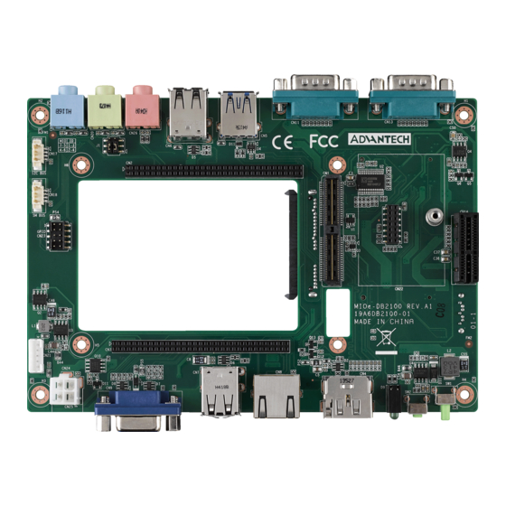
2 USB2.0 DP/HDMI CN24 Power/ HDD LED Figure 2.1 Jumper and Connector layout (Top side) Mini PCIe CN10 CN14 SATA with Power (2.5” HDD) SATA CN12 SIM Card Holder CN15 Figure 2.2 Jumper and Connector layout (Bottom side) MIOe-DB2100 User Manual... -
Page 21: Jumper And Connector Pin Definition
PIN HEADER 3*2P 180D(M) 2.0mm SMD SOUARE PIN Setting Function (1-2)(3-4) Internal 64Pin connector (3-5)(4-6) MIOe Default is (1-2)(3-4)-Internal 64Pin connector. MIOe Part Number 1654009899 Footprint MIOE Description MIOE Module on I/O function Board Pin Name PCIE_RX0+ PCIE_TX0+ PCIE_RX0- PCIE_TX0- PCIE_RX1+ PCIE_TX1+ PCIE_RX1- PCIE_TX1- MIOe-DB2100 User Manual... - Page 22 PCIE_CLK+ LOUTL PCIE_CLK- LOUTR AGND SMB_CLK SMB_DAT PCIE_WAKE# RESET# SLP_S3# CLK33M LPC_AD0 DDP_HPD LPC_AD1 LPC_AD2 DDP_AUX+ LPC_AD3 DDP_AUX- LPC_DRQ#0 LPC_SERIRQ DDP_D0+ LPC_FRAME# DDP_D0- USB0_D+ DDP_D1+ USB0_D- DDP_D1- USB1_D+ DDP_D2+ USB1_D- DDP_D2- USB2_D+ MIOe-DB2100 User Manual...
- Page 23 DDP_D3+ USB2_D-- DDP_D3- USB_OC# +12 VSB +12 VSB +5 VSB +5 VSB +5 VSB +5 VSB MIOe-DB2100 User Manual...
- Page 24 PIN HEADER 32x2P 2.0mm 180D(F) DIP 22N8242-64S10 Pin Name PSIN# Reset HD LED +V5_SMB SMB_DAT SMB_CLK I2C_DAT I2C_CLK +V5_GPIO GPIO4 GPIO0 GPIO5 GPIO1 GPIO6 GPIO2 GPIO7 GPIO3 +V5_USB34 +V5_USB34 USB4_P- USB3_P- USB4_P+ USB3_P+ LOUTR LINR GND_AUD GND_AUD LOUTL LINL GND_AUD GND_AUD MIOe-DB2100 User Manual...
- Page 25 MICR MICL COM0_DCD# COM0_DSR# COM0_RXD COM0_RTS# COM0_TXD COM0_CTS# COM0_DTR# COM0_RI# COM1_DCD# COM1_DSR# COM1_RXD COM1_RTS# COM1_TXD COM1_CTS# COM1_DTR# COM1_RI# MIOe-DB2100 User Manual...
- Page 26 Internal 64Pin Connector A Part Number 1653005340-01 Footprint HD_32x2P_79_F_D Description PIN HEADER 32x2P 2.0mm 180D(F) DIP 22N8242-64S10 Pin Name +V12_DC_IN +V12_DC_IN + +V12_DC_IN +V12_DC_IN LVDS0_ENABKL LVDS0_VBR VGA_DDAT VGA_DCLK VGA_R VGA_G VGA_B +V5_VGA VGA_HS VGA_VS +V5_USB01 +V5_USB01 USB0_z_P- USB1_z_P- MIOe-DB2100 User Manual...
- Page 27 USB0_z_P+ USB1_z_P+ LINK100#_LED LINK1000#_LED ACT#_LED LAN0_M0+ LAN0_M0- LAN1_M0+ LAN1_M0- LAN2_M0+ LAN2_M0- LAN3_M0+ LAN3_M0- GNDT1 GNDT1 MIOe-DB2100 User Manual...
- Page 28 GND/TMDS Data1 Shield ML_Lane1(n)/TMDS Data1– ML_Lane2(p)/TMDS Data0+ GND/TMDS Data0 Shield ML_Lane2(n)/TMDS Data0– ML_Lane3(p)/TMDS Clock+ GND/TMDS Clock Shield ML_Lane3(n)/TMDS Clock– CONFIG1/Reserved CONFIG2/Reserved AUX CH(p)/SCL GND/SDA AUX CH(n)/DDC Ground Hot Plug Detect/+5 V Power GND/Hot Plug Detect +3.3 V MIOe-DB2100 User Manual...
- Page 29 External USB3.0 Part Number 1654009746 Footprint USB_9P_UEA1112C-4HK1-4H Description USB CONN. 9P 2.0mm 90D(F) DIP UEA1112C-4HK1-4H Pin Name SSRX- SSRX+ SSTX- SSTX+ External USB2.0 Part Number 1654009513 Footprint USB_8P_UB1112C-8FDE-4F Description USB CONN. 8P 2.0mm 90D DIP UB1112C-8FDE-4F Pin Name MIOe-DB2100 User Manual...
- Page 30 1654009513 Footprint USB_8P_UB1112C-8FDE-4F Description USB CONN. 8P 2.0mm 90D DIP UB1112C-8FDE-4F Pin Name Gigabit Ethernet Part Number 1652000279 Footprint RJ45_12P_RJ1401 Description PHONE JACK RJ45 14P DIP RJ1401-88UE50R500 Pin Name BI_DA+(GHz) BI_DA-(GHz) BI_DB+(GHz) BI_DC+(GHz) BI_DC-(GHz) BI_DB-(GHz) BI_DD+(GHz) BI_DD-(GHz) MIOe-DB2100 User Manual...
- Page 31 D-SUB CONN. 15P 90D(F) DIP 5mm BLUE W/O Pb Pin Name GREEN BLUE +V5_VGA DDAT HSYNC VSYNC DCLK CN10 SATA Ouput Part Number 1654010207 Footprint SATA_22P_WATB-22DL1P5U Description Serial ATA 22P 1.27mm 90D(F) DIP WATB-22DL1P5U Pin Name +V3.3 +V3.3 +V3.3 MIOe-DB2100 User Manual...
- Page 32 +V12 +V12 +V12 CN11 COM1 Part Number 1654011267-01 Footprint DB_9P_DSB5-09M1-GNR0-5G Description D-sub 9P 2.775mm 90D(M) DIP DSB5-09M1-GNR0-4G Pin Name DCD# DTR# DSR# RTS# CTS# MIOe-DB2100 User Manual...
- Page 33 Footprint DB_9P_DSB5-09M1-GNR0-5G Description D-sub 9P 2.775mm 90D(M) DIP DSB5-09M1-GNR0-4G Pin Name DCD# DTR# DSR# RTS# CTS# CN14 Mini PCIE Part Number 1654002538 Footprint FOX_AS0B226-S68K7F Description MINI PCI express 52P 90D SMD H=6.8mm Pin Name WAKE# +3.3 VSB MIOe-DB2100 User Manual...
- Page 34 +1.5 V REFCLK- REFCLK+ PERST# PERn0 +3.3 VSB PERp0 +1.5 V SMB_CLK PETn0 SMB_DAT PETp0 USB D- USB D+ +3.3 VSB +3.3 VSB +1.5V MIOe-DB2100 User Manual...
- Page 35 SIM card conn. 6p 2.54mm 90D(F) SMD 5210622-SINR Pin Name UIM_PWR UIM_RESET UIM_CLK UIM_VPP UIM_DATA CN16 PCIEx1 Slot Part Number 1654011366-01 Footprint PCIE_36P_AAA-PCI-003-K02 Description PCIEXPRESS 36P 1.0mm 180D(F) DIP 15u" AAA-PCI-15 Pin Name +12 V +12 V MIOe-DB2100 User Manual...
- Page 36 +12 V +12 V SMB_CLK SMB_DAT +3.3 V JTAG1 +3.3 VSB PCIE_WAKE# HSOP0 HSON0 CN17 I2C BUS Part Number 1655904020 Footprint FPC4V-125M Description Wafer SMT 1.25mmS/T type 4P 180D(M) 85205-04001 Pin Name I2C DATA I2C CLK +5 V MIOe-DB2100 User Manual...
- Page 37 PHONE JACK 3.5φ5P 90D(F) BLUE W/SHIELDED Pin Name GND_AUD LINEIN_L LINEIN_L LINEIN_R LINEIN_R CN20 HD Audio Line Out Part Number 1652505205 Footprint FOX_JA13331-N24B-4F Description PHONE JACK 3.5φ5P 90D(F) LIME W/SHIELDED Pin Name GND_AUD LINEOUT_L LINEOUT_L LINEOUT_R LINEOUT_R MIOe-DB2100 User Manual...
- Page 38 WAFER BOX 2.0mm 5P 180D(M) DIP WO/Pb JIH VEI Pin Name +12 V ENABKL +5 V CN22 Part Number 1653007270 Footprint LPC_BOARD_PCE-5026_SMD Description FEMALE HEADER 7x2P 2.0mm 180D(F) SMD 22P8242 Pin Name CLK33M_LPC LPC_AD1 RESET# LPC_AD0 LPC_FRAME# +V3.3 LPC_AD3 LPC_AD2 LPC_SERIRQ +V5SB MIOe-DB2100 User Manual...
- Page 39 DC POWER JACK Screw 3P 2.5Φ 90D(M) DIP DCJ-RPB Pin Name +VIN CN25 12 V Power Input Part Number 1655004584-01 Footprint WF_2x2P_165_BOX_D Description ATX PWR CONN. 2x2P 4.2mm 180D(M) DIP 24W4310-04S Pin Name +12 V IN +12 V IN MIOe-DB2100 User Manual...
- Page 40 CN26 HD Audio Mic in Part Number 1652505203 Footprint FOX_JA13331-N24B-4F Description PHONE JACK 3.5PHI 5P 90D(F) DIP JA13331-N21B-4F Pin Name GND_AUD MICIN_L MICIN_L MICIN_R MICIN_R MIOe-DB2100 User Manual...
-
Page 41: Quick Installation Guide
Quick Installation Guide There are four posts and screws inside the MIO-3260 package, please install the DRAM in the SODIMM socket on MIO-3260 first, then screw the heatsink into place as per illustration below: MIOe-DB2100 User Manual... - Page 42 No part of this publication may be reproduced in any form or by any means, electronic, photocopying, recording or otherwise, without prior written permis- sion of the publisher. All brand and product names are trademarks or registered trademarks of their respective companies. © Advantech Co., Ltd. 2015...
- Page 43 Free Manuals Download Website h p://myh66.com h p://usermanuals.us h p://www.somanuals.com h p://www.4manuals.cc h p://www.manual-lib.com h p://www.404manual.com h p://www.luxmanual.com h p://aubethermostatmanual.com Golf course search by state h p://golfingnear.com Email search by domain h p://emailbydomain.com Auto manuals search h p://auto.somanuals.com TV manuals search h p://tv.somanuals.com...
Need help?
Do you have a question about the MIOe-DB2100 and is the answer not in the manual?
Questions and answers