
Related Manuals for Advantech MIO-2361 Series


Summary of Contents for Advantech MIO-2361 Series
- Page 1 User Manual MIO-2361 Intel® Atom™ E3900 series/ Pentium N4200/Celeron N3350, Pico-ITX SBC, Onboard LPDDR4, eMMC, 48-bit LVDS, HDMI, 2 GbE, USB3.0, 2 COM, M.2 E-key 2230, F/S mSATA, opt. mPCIe, SMBus...
- Page 2 The documentation and the software included with this product are copyrighted 2019 by Advantech Co., Ltd. All rights are reserved. Advantech Co., Ltd. reserves the right to make improvements in the products described in this manual at any time without notice.
- Page 3 Because of Advantech’s high quality-control standards and rigorous testing, most of our customers never need to use our repair service. If an Advantech product is defec- tive, it will be repaired or replaced at no charge during the warranty period. For out- of-warranty repairs, you will be billed according to the cost of replacement materials, service time and freight.
- Page 4 Packing List Before installation, please ensure the following items have been shipped: Item Part Number 1 MIO-2361 SBC 1 Startup manual Cables Part Number Description 1700006291 SATA cable 7P 30 cm w/ right angle 1701200220 COM PORT cable 2*10P-2.0/D-SUB 9P(M)*2 22 cm 1700027546-01 A cable 1*5P-2.0/1*5P-2.0+SATA 15P 15cm MIO-236 1700002172...
- Page 5 Declaration of Conformity This device complies with the requirements in part 15 of the FCC rules: Operation is subject to the following two conditions: This device may not cause harmful interference, and This device must accept any interference received, including interference that may cause undesired operation FCC Class B Note: This equipment has been tested and found to comply with the limits for a Class...
- Page 6 The sound pressure level at the operator's position according to IEC 704-1:1982 is no more than 70 dB (A). DISCLAIMER: This set of instructions is given according to IEC 704-1. Advantech disclaims all responsibility for the accuracy of any statements contained herein.
- Page 7 Safety Precaution - Static Electricity Follow these simple precautions to protect yourself from harm and the products from damage. To avoid electrical shock, always disconnect the power from your PC chassis before you work on it. Don't touch any components on the CPU card or other cards while the PC is on.
- Page 8 MIO-2361 User Manual viii...
-
Page 9: Table Of Contents
Contents Chapter General Introduction ......1 Introduction ....................2 Specifications .................... 2 1.2.1 General Specifications ..............2 1.2.2 OS Support List................3 1.2.3 Functional Specifications .............. 3 1.2.4 Mechanical Specifications............. 4 1.2.5 Electrical Specifications ..............4 1.2.6 Environmental Specifications............5 Function Block Diagram ................6 Chapter Installation........7 Jumpers .................... - Page 10 4.3.3 SUSI Installation ................. 46 4.3.4 SUSI Sample Programs.............. 47 Appendix A PIN Assignments ......55 Jumper Settings ..................56 Connectors....................58 Table A.1: Connector list ............58 Appendix B WDT & GPIO ........73 Watchdog Timer Sample Code............... 74 GPIO Sample Code ................
-
Page 11: Chapter 1 General Introduction
Chapter General Introduction This chapter gives background information on the MIO-2361. Sections include: Introduction Product Features Specifications... -
Page 12: Introduction
64GB (TBC), Dual GbE, USB3.0, 2 x RS-232/422/485, 12/24V input; the board also supports Dual independent display by 48-bit LVDS & HDMI.Besides, MIO- 2361 has M.2 E-key, mSATA/mPCIe for expansion. MIO-2361, Advantech Innovative Extension SBC, is equipped with flexible multiple I/O functions to assist integrators in developing optimized solutions. -
Page 13: Os Support List
1.2.2 OS Support List Windows 10 (×64) Yes (UEFI mode only) Yocto Yocto BSP (Support by request) 1.2.3 Functional Specifications Processor Intel® Pentium N4200/Celeron N3350 Intel® Atom™E3950/Intel® Atom™E3940/Intel® Atom™E3930 Frequency – N4200: 2.50 GHz Processor – N3350: 2.40 GHz –... -
Page 14: Mechanical Specifications
BIOS AMI EFI 64 Mbit Flash BIOS via SPI Storage 32GB (default). eMMC 64GB* (optional, TBC) Note#1: verified with 1410028472-01/SQF-MM5M2-32G-M5E Expansion E-Key 2230 (PCIe x1, USB2.0) mPCIe/mSATA 1/1*(optional) Others Controller: Intel® i210IT/i210AT Compliant with IEEE 802.3, IEEE 802.3u, IEEE 802.3z, IEEE ... -
Page 15: Environmental Specifications
1.2.5.2 Power Consumption Typical in Windows 10 Idle Mode: E3950: 8.59 W (12V) E3950: 8.81 W (24V) Max in Windows 10 HCT12 (10 minutes): E3950: 26.27 W (12V) E3950: 26.51 W (24V) 1.2.5.3 RTC Battery Typical Voltage: 3.0 V ... -
Page 16: Function Block Diagram
Function Block Diagram LPDDR4 2400 onboard memory, up to 8GB PCIe x1 HDMI Full-size Mini-PCIe/ SATAIII 600MB/s Full-size mSATA* (optional) USB2.0 48-bit PTN3460 LVDS SATAIII 600MB/s Atom E3900 Series 1 SATAIII Pentium N4200 PCIex1 USB3.0/USB2.0 Celeron N3350 2 USB3.0 USB2.0 (E-Key 2230) 1.8~2.0GHz AMI BIOS... -
Page 17: Chapter 2 H/W Installation
Chapter H/W Installation This chapter explains the setup procedures of the MIO-2361 hard- ware, including instructions on setting jumpers and connecting peripherals, as well as switches, indicators and mechanical draw- ings. Be sure to read all safety precautions before you begin the installation procedure. -
Page 18: Jumpers
Jumpers 2.1.1 Jumper Description Cards can be configured by setting jumpers. To close a jumper, you connect the pins with the clip. To open a jumper, you remove the clip. Sometimes a jumper will have three pins, labeled 1, 2 and 3. In this case you would connect either pins 1 and 2, or 2 and 3. -
Page 19: Connectors
Connectors 2.2.1 Connector List 12 V Power Input DC JACK Battery CN10 CN12 48-bit LVDS Panel CN13 HDMI CN15 SATA CN16 Audio CN18 Mini PCIE CN22 External USB3.0 CN23 SMBus CN33 Internal USB CN34 GPIO CN35 GPIO CN45 Front panel CN54 COM1/COM2 CN57... - Page 20 HDMI display connector (CN13) Supports HDMI1.4b. Resolution: up to 3840 x 2160 at 30Hz. LVDS LCD panel connector (CN12) MIO-2361 supports dual channel 48-bit LVDS LCD panel displays. Resolution: up to 1920 x 1200. 2.2.2.5 Front Panel Connector(CN45) MIO-2361 integrates below functions as front panel 9-pin connector. Power button Supports power on/off button in ATX mode.
- Page 21 SMBus Connector (CN23) MIO-2361 provides SMBus connector for customer connection to SMBus protocol embedded device. Advantech also provide SMBus API allowing developers to inter- face with an embedded system environment and transfer serial messages using the SMBus protocols, allowing multiple simultaneous device control.
-
Page 22: Mechanical
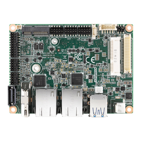
Mechanical 2.3.1 Jumper and Connector Locations CN34 CN23 CN33 CN57 CN35 M.2 2230 CN54 CN12 CN16 CN18 CN45 CN15 CN13 CN10 CN22 Figure 2.1 MIO-2361 Connector Locations (Bottom Side) MIO-2361 User Manual... -
Page 23: Board Dimensions
2.3.2 Board Dimensions 2.3.2.1 CPU Board Drawing 68.75 68.75 36.71 3.25 Figure 2.2 MIO-2361 Mechanical Drawing (Top Side) 68.75 68.75 67.63 59.96 46.07 35.24 34.08 24.42 3.25 3.25 Figure 2.3 MIO-2361 Mechanical Drawing (Bottom Side) MIO-2361 User Manual... - Page 24 11.74 28.89 49.25 69.53 100.00 Figure 2.4 MIO-2361 Mechanical Drawing (Side View) 11.74 28.89 49.25 69.53 100.00 Figure 2.5 MIO-2361 Mechanical Drawing (Side View with Heatsink) MIO-2361 User Manual...
- Page 25 2.3.2.2 MI/O Module Height Constraint To avoid mechanical conflict with MI/O-Ultra CPU board, it's recommended to refer to the following drawing for MI/O module height constraints. unit: mm Figure 2.6 MI/O module height constraints Note! Height of MI/O module is based on 16 mm height MIOe connector. If needed, there's a 19 mm height connector as well.
- Page 26 For best heat conduction, the gap between the chassis and heat spreader should be smaller, the smaller the better. The height of the existing heat spreader is TBD (Advantech P/N: TBD). If you need some other height to fit the chassis better, Advantech can customize it for you.
-
Page 27: Chapter 3 Bios Settings
Chapter BIOS Settings... - Page 28 With the AMIBIOS Setup program, you can modify BIOS settings and control the var- ious system features. This chapter describes the basic navigation of the MIO-2361 BIOS setup screens. AMI BIOS ROM has a built-in Setup program that allows users to modify the basic system configuration.
-
Page 29: Entering Setup
BIOS supports your CPU. If there is no number assigned to the patch code, please contact an Advantech application engineer to obtain an up-to-date patch code file. This will ensure that your CPU's system status is valid. - Page 30 System time / System date Use this option to change the system time and date. Highlight System Time or Sys- tem Date using the <Arrow> keys. Enter new values through the keyboard. Press the <Tab> key or the <Arrow> keys to move between fields. The date must be entered in MM/DD/YY format.
-
Page 31: Advanced Bios Features Setup
3.1.2 Advanced BIOS Features Setup Select the Advanced tab from the MIO-2361 setup screen to enter the Advanced BIOS Setup screen. You can select any of the items in the left frame of the screen, such as CPU Configuration, to go to the sub menu for that item. You can display an Advanced BIOS Setup option by highlighting it using the <Arrow>... - Page 32 3.1.2.1 Driver Health Provide Health Status for the Drivers/Controllers. 3.1.2.2 Trusted Computing Security Device Support Enable or disable BIOS support for security device. SHA-1 PCR Bank Enable or disable SHA-1 PCR Bank. MIO-2361 User Manual...
- Page 33 SHA256 PCR Bank Enable or disable SHA256 PCR Bank. Pending operation Schedule an Operation for the Security Device. Platform Hierarchy Enable or disable Platform Hierarchy. Storage Hierarchy Enable or disable Storage Hierarchy. Endorsement Hierarchy Enable or disable Endorsement Hierarchy. TPM 2.0 UEFI Spec Version ...
- Page 34 Lock Legacy Resources Enable or disable Lock of Legacy Resources 3.1.2.4 iManager Configuration CPU Shutdown Temperature CPU Shutdown Temperature settings. Backlight Enable Polarity Switch Backlight Enable Polarity for Native or Invert. Backlight Mode Selection Switch Backlight Control to PWM or DC mode. ...
- Page 35 3.1.2.5 S5 RTC Wake Settings Wake system from S5 Enable or disable system wake on alarm event. Selecting FixedTime, system will wake on hr:min:sec as specified. 3.1.2.6 Serial Port Console Redirection MIO-2361 User Manual...
- Page 36 Console Redirection This item allows users to enable or disable console redirection for Microsoft Windows Emergency Management Services (EMS). Console Redirection This item allows users to configure console redirection detail settings. 3.1.2.7 CPU Configuration Intel Virtualization Technology When enabled, a VMM can utilize additional hardware capabilities provided by Vanderpool Technology.
- Page 37 3.1.2.8 Network Stack Configuration Network Stack Enable/Disable UEFI Network Stack. 3.1.2.9 CSM Configuration CSM Support Enable/Disable CSM Support (*CSM Support for debug purpose) MIO-2361 User Manual...
- Page 38 Gate A20 Active This item is useful when RT code is executed above 1MB. When this is set as "Upon Request" GA20 can be disabled using BIOS services. When it's set as "Always", it does not allow disabling GA20. ...
- Page 39 3.1.2.11 USB Configuration Legacy USB Support Enables Legacy USB support. AUTO option disables legacy support if no USB devices are connected. DISABLE option will keep USB devices available only for EFI applications. XHCI Hand-off This is a workaround for OS without XHCI hand-off support. The XHCI owner- ship change should be claimed by XHCI driver.
-
Page 40: Chipset Configuration
3.1.2.12 Security Configuration TXE HMRFPO Disable TXE EOP Message Sends EOP Message Before Entering OS 3.1.3 Chipset Configuration MIO-2361 User Manual... - Page 41 North Bridge Details for North Bridge items. South Bridge Details for South Bridge items. Uncore Configuration Details for Uncore Configuration. South Cluster Configuration Details for South Cluster Configuration. 3.1.3.1 North Bridge Max TOLUD Maximum Value of TOLUD. MIO-2361 User Manual...
- Page 42 3.1.3.2 South Bridge Serial IRQ Mode Configure Serial IRQ Mode. SMBus Support Enable/Disable SMBus Support. OS Selection Select the target OS. MIO-2361 User Manual...
- Page 43 3.1.3.3 Uncore Configuration Color depth & data packing format Select color depth and data packing format for Non-EDID. Default support is enabled. Dual LVDS mode Select LVDS bus to Single bus mode or Dual bus mode. LVDS Panel Type Select LCD Panel Type.
- Page 44 PAVP Enable Enable/Disable PAVP. Memory Scrambler Enable/Disable Memory Scrambler support. 3.1.3.4 South Cluster Configuration HD-Audio Configuration HD-Audio Configuration settings. PCI Express Configuration PCI Express Configuration Settings. SATA Drives Press <Enter> to select the SATA Drive configuration setup options. ...
- Page 45 HD-Audio Configuration HD-Audio Support Enable/Disable HD-Audio Support. PCI Express Configuration MIO-2361 User Manual...
- Page 46 PCI Express Clock Gating PCI Express Clock Gating Enable/Disable. Peer Memory Write Enable Peer Memory Write Enable/Disable. Compliance Mode Compliance Mode Enable/Disable. PCI Express Root Port 5 / 6 Control the PCI Express Root Port. Onboard LAN1/LAN2 Controller Select enable or disable Onboard LAN1/LAN2 Controller.
- Page 47 SCC Configuration SCC eMMC Support (D28:F0) Enable/Disable SCC eMMC Support. eMMC Max Speed Select the eMMC Max Speed allowed. MIO-2361 User Manual...
- Page 48 USB Configuration XHCI Pre-Boot Driver Enable/Disable XHCI Pre-Boot Driver support. USB Port Disable Override Selectively Enable/Disable corresponding USB port from reporting a device connection to the controller. XHCI Disable Compliance Mode Options to disable XHCI link compliance mode. ...
- Page 49 Miscellaneous Configuration Restore AC Power Loss Specify what state to go to when power is re-applied after a power failure (G3 state). BIOS Lock Enable/Disable the BIOS lock enable feature. RTC Lock Enable or disable bytes 38h-3Fh in the upper and lower 128-byte bank of RTC RAM lockdown.
-
Page 50: Security
3.1.4 Security Select Security Setup from the MIO-2361 Setup main BIOS setup menu. All Security- Setup options, such as password protection and virus protection are described in this section. To access the sub menu for the following items, select the item and press <Enter>: ... -
Page 51: Boot
3.1.5 Boot Setup Prompt Timeout Number of seconds that the firmware will wait before initiating the original default boot selection. A value of 0 indicates that the default boot selection is to be initiated immediately on boot. A value of 65535 (0xFFFF) indicates that firm- ware will wait for user input before booting. -
Page 52: Save & Exit
3.1.6 Save & Exit Save Changes and Exit This item allows you to exit system setup after saving the changes. Discard Changes and Exit This item allows you to exit system setup without saving any changes. Save Changes and Reset ... -
Page 53: Chapter 4 S/W Introduction & Installation
Chapter S/W Introduction & Installation... -
Page 54: S/W Introduction
Application programmers can invoke the functions exported by SUSI instead of call- ing the drivers directly. The benefit of using SUSI is portability. The same set of APIs is defined for different Advantech hardware platforms. Also, the same API set is implemented in different Operating Systems. This user’s manual describes some sample programs and the API in SUSI. -
Page 55: Software Apis
However, due to the inaccuracy among many commercially available hardware mon- itoring chips, Advantech has developed a unique scheme for hardware monitoring - achieved by using a dedicated micro-processor with algorithms specifically designed for providing accurate, real-time and reliable data content; helping protect your sys- tem in a more reliable manner. -
Page 56: Susi Installation
4.3.3 SUSI Installation SUSI supports many different operating systems. Each subsection below describes how to install SUSI and related software on a specific operating system. Please refer to the subsection matching your operating system. 4.3.3.1 Windows 10 In Windows 10, you can install the library, drivers and demo programs onto the plat- form easily using the SUSI Library Installer tool. -
Page 57: Susi Sample Programs
4.3.4 SUSI Sample Programs Sample Programs The sample programs demonstrate how to incorporate SUSI into your program. The sample programs run in graphics mode in Windows® 7 are described in the subsec- tions below. Windows Graphics Mode Each demo application contains an executable file SusiDemo.exe, a shared library Susi.dll and source code within the release package. - Page 58 GPIO When the application is executed, it will display GPIO information in the GPIO INFORMATION group box. It displays the number of input pins and output pins. You can click the radio button to choose to test either the single pin function or multiple pin functions.
- Page 59 Test Write Multiple Output Pins – Click the radio button- Multi-Pin. – Key in the pin number from ‘0x01’ to ‘0x0F’ to choose the multiple pin num- bers to write the value of the output pin. The pin numbers are ordered bit- wise, i.e.
- Page 60 Write a byte – Click the radio button- Access a byte. – Key in the slave device address in Slave address field. – Key in the register offset in Register Offset field. – Key the desired data in the Result field to write to the device. –...
- Page 61 Display Control When the application is executed, it will display two blocks of VGA control functions. The application can turn on or turn off the screen shot freely, and it also can tune the brightness of the panels if your platform is supported. You can test the functionality of VGA control as follows: ...
- Page 62 Watchdog When the application is executed, it will display watchdog information in the WATCH- DOG INFORMATION group box. It displays max timeout, min timeout, and timeout steps in milliseconds. For example, a 1~255 seconds watchdog will have 255000 max timeout, 1000 min timeout, and 1000 timeout steps. You can test the functional- ity of the watchdog as follows: ...
- Page 63 If certain data values are not supported by the platform, the correspondent data field will be grayed-out with a value of 0. For more details on MIO-2361 software API, please contact your dealer or Advantech MIO-2361 User Manual...
- Page 64 MIO-2361 User Manual...
-
Page 65: Pin Assignments
Appendix PIN Assignments... -
Page 66: Jumper Settings
Jumper Settings Auto Power On Part Number Footprint SW_4×2P_50_260×220 Setting Function (1-8) ON: AT mode OFF: ATX mode LVDS VCON Part Number Footprint SW_4×2P_50_260×220 Setting Function LVDS JEIDA/VESA select (2-7) ON: GND OFF: +V3.3 MIO-2361 User Manual... - Page 67 DCIN 12V Part Number Footprint SW_4×2P_50_260×220 Setting Function (4-5) ON: DCVIN=12V OFF: DCIN=24V DCIN 12V Part Number Footprint SW_4×2P_50_260×220 Setting Function (1-8) ON: DCVIN=12V OFF: DCIN=24V (2-7) ON: DCVIN=12V OFF: DCIN=24V DCIN 24V Part Number Footprint SW_4×2P_50_260×220 Setting Function (3-6) ON: DCVIN=24V OFF: DCIN=12V DCIN 24V Part Number...
-
Page 68: Connectors
Connectors Table A.1: Connector list 12 V Power Input DC JACK Battery CN10 CN12 48-bit LVDS Panel CN13 HDMI CN15 SATA CN16 Audio CN18 Mini PCIE CN22 External USB3.0 CN23 SMBus CN33 Internal USB CN34 GPIO CN35 GPIO CN45 Front panel CN54 COM1/COM2 CN57... - Page 69 12 V Power Input Part Number 1655003962 Footprint WF_2P_156_D_A3963WV2 Description WAFER 2P 3.96mm 180D(M) DIP A3963WV2-2P Pin Name +VIN DCJACK_3 Part Number Footprint PJ_3P_SCD556DCS113B00G Description Pin Name +VIN Battery Part Number 1655902032 Footprint WHL2V-125 Description WAFER BOX 2P 1.25mm 180D(M) DIP 53047-0210 Pin Name MIO-2361 User Manual...
- Page 70 LAN1 Part Number 1652004356 Footprint RJ45_14P_RT7-194AAM1A Description PHONE JACK RJ45 14P 90D(F) DIP RT7-194AAM1A Pin Name BI_DA+(GHz) BI_DA-(GHz) BI_DB+(GHz) BI_DC+(GHz) BI_DC-(GHz) BI_DB-(GHz) BI_DD+(GHz) BI_DD-(GHz) CN10 LAN2 Part Number 1652004356 Footprint RJ45_14P_RT7-194AAM1A Description PHONE JACK RJ45 14P 90D(F) DIP RT7-194AAM1A Pin Name BI_DA+(GHz) BI_DA-(GHz) BI_DB+(GHz)
- Page 71 CN12 48-bit LVDS Panel Part Number 1653006918-01 Footprint SPH20X2 Description Pin Name +5V or +3.3V +5V or +3.3V +5V or +3.3V +5V or +3.3V LVDS0_D0- LVDS1_D0- LVDS0_D0+ LVDS1_D0+ LVDS0_D1- LVDS1_D1- LVDS0_D1+ LVDS1_D1+ LVDS0_D2- LVDS1_D2- LVDS0_D2+ LVDS1_D2+ LVDS0_CLK- LVDS1_CLK- MIO-2361 User Manual...
- Page 72 CN12 48-bit LVDS Panel Part Number 1653006918-01 Footprint SPH20X2 Description Pin Name LVDS0_CLK+ LVDS1_CLK+ LVDS0_D3- LVDS1_D3- LVDS0_D3+ LVDS1_D3+ VCON MIO-2361 User Manual...
- Page 73 CN15 SATA Part Number 1654013615-01 Footprint sata_7p_watf-07dbn6sb1u Description Pin Name CN16 Audio Part Number 1653004099 Footprint HD_5x2P_79_23N685B-10M10 Description BOX HEADER 5x2P 2.00mm 180D(M) SMD 23N685B-10M10 Pin Name LOUTR LINR LOUTL LINL MIC1R MIC1L MIO-2361 User Manual...
- Page 74 CN18 Mini PCIE Part Number 1654002538 Footprint FOX_AS0B226-S68K7F Description MINI PCI E 52P 6.8mm 90D SMD AS0B226-S68Q-7H Pin Name WAKE# +3.3VSB +1.5V CLKREQ# REFCLK- REFCLK+ W_DISABLE# PERST# PERn0 +3.3VSB PERp0 MIO-2361 User Manual...
- Page 75 CN18 Mini PCIE Part Number 1654002538 Footprint FOX_AS0B226-S68K7F Description MINI PCI E 52P 6.8mm 90D SMD AS0B226-S68Q-7H Pin Name +1.5V SMB_CLK PETn0 SMB_DAT PETp0 USB D- USB D+ +3.3VSB +3.3VSB +1.5V +3.3VSB MIO-2361 User Manual...
- Page 76 CN22 External USB3.0 Part Number 1654012030-01 Footprint USB_9X2P_USB5-18F5-BNR0-10 Description Pin Name SSRX- SSRX+ SSTX- SSTX+ CN23 SMBus Part Number 1655904020 Footprint FPC4V-125M Description WAFER 4P 1.25mm 180D(M) SMD 85205-04001 Pin Name SMB_DAT SMB_CLK MIO-2361 User Manual...
- Page 77 CN31 IS200 Debug Port Part Number 1654010149 Footprint FPCCON_8P_20_88706-0801 Description Pin Name +V3.3RDC +V3.3EC CN33 Internal USB Part Number 1653004515 Footprint HD5x2P_79_23N685B-10M10_N10 Description Pin Name A_D- B_D- A_D+ B_D+ MIO-2361 User Manual...
- Page 78 CN34 GPIO Part Number 1653004099 Footprint HD_5x2P_79_23N685B-10M10 Description BOX HEADER 5x2P 2.00mm 180D(M) SMD 23N685B-10M10 Pin Name GPIO4 GPIO0 GPIO5 GPIO1 GPIO6 GPIO2 GPIO7 GPIO3 CN35 GPIO Part Number 1653004099 Footprint HD_5x2P_79_23N685B-10M10 Description BOX HEADER 5x2P 2.00mm 180D(M) SMD 23N685B-10M10 Pin Name GPIO4 GPIO0...
- Page 79 CN45 Front Panel Part Number 1653004099 Footprint HD_5x2P_79_23N685B-10M10 Description BOX HEADER 5x2P 2.00mm 180D(M) SMD 23N685B-10M10 Pin Name Power Button Reset Button PWR LED CASEOPEN# SATA LED+ SATA LED- BUZZER+ BUZZER- CN51 BIOS Debug Part Number 1653000126 Footprint HD_4x2P_50_H235 Description PIN HEADER 2x4P 180D(M) 1.27mm SMD FTSH-104-01-F Pin Name +1.8VSB...
- Page 80 CN54 COM1/COM2 Part Number 1653004793 Footprint HD_10x2P_79_23N685B-20M10 Description BOX HEADER 10x2P 2.0mm 180D(M)SMD 23N685B-20M10B Pin Name DCD1# DSR1# RXD1 RTS1# TXD1 CTS1# DTR1# RI1# DCD2# DSR2# RXD2 RTS2# TXD2 CTS2# DTR2# RI2# MIO-2361 User Manual...
- Page 81 CN57 Inverter Power Output Part Number 1655305220 Footprint WF_5P_79_BOX Description WAFER BOX 2.0mm 5P 180D SMD(M) W/LOCK Pin Name +12V ENABKL CN59 Part Number 1655302020 Footprint WF_2P_79_BOX_R1_D Description WAFER BOX 2P 2.0mm 180D(M) DIP A2001WV2-2P Pin Name +12V MIO-2361 User Manual...
- Page 82 CN13 HDMI Part Number 1654010746-01 Footprint HDMI_19P_QJ3119C-WFB1-4F Description Pin Name TMDS Data2+ TMDS Data2 Shield TMDS Data2- TMDS Data1+ TMDS Data1 Shield TMDS Data1- TMDS Data0+ TMDS Data0 Shield TMDS Data0- TMDS Clock+ TMDS Clock Shield TMDS Clock- Reserved Reserved DDC Ground +5V Power Hot Plug Detect...
-
Page 83: Wdt & Gpio
Appendix WDT & GPIO... -
Page 84: Watchdog Timer Sample Code
Watchdog Timer Sample Code Watchdog function: The SCH3114 Runtime base I/O address is A00h Setting WatchDog time value location at offset 66h If set value "0", it is mean disable WatchDog function. Superio_GPIO_Port = A00h mov dx,Superio_GPIO_Port + 66h mov al,00h out dx,al .model small .486p... -
Page 85: Gpio Sample Code
;==================================================== mov dx,SCH3114_IO + 68h mov al,01h out dx,al .exit GPIO Sample Code The SCH3114 Runtime base I/O address is A00h .model small .486p .stack 256 .data SCH3114_IO EQU A00h .code org 100h .STARTup ;==================================================== ; Configuration GPIO as GPI or GPO by below register: ;... - Page 86 MIO-2361 User Manual...
-
Page 87: System Assignments
Appendix System Assignments... -
Page 88: System I/O Ports
System I/O Ports Table C.1: System I/O Ports Addr. Range (Hex) Device 20–2D Interrupt Controller 2E – 2F Motherboard resources 30 – 3D Interrupt Controller 40 – 43 System timer 4E – 4F Motherboard resources 50 – 53 System timer 61 –... -
Page 89: Interrupt Assignments
Interrupt Assignments Table C.3: Interrupt assignments Interrupt# Interrupt Source Parity error detected IRQ0 System timer IRQ1 Using SERIRQ, Keyboard Emulation IRQ2 Slave controller INTR output IRQ3 Communications Port (COM2) IRQ4 Communications Port (COM1) IRQ5 Available IRQ6 Available IRQ7 Available IRQ8 Internal RTC or HPET IRQ9 Microsoft ACPI-Compliant System... - Page 90 No part of this publication may be reproduced in any form or by any means, electronic, photocopying, recording or otherwise, without prior written permis- sion of the publisher. All brand and product names are trademarks or registered trademarks of their respective companies. © Advantech Co., Ltd. 2019...
Need help?
Do you have a question about the MIO-2361 Series and is the answer not in the manual?
Questions and answers