Sign In
Upload
Manuals
Brands
Burkert Manuals
Measuring Instruments
FLOWave L
Burkert FLOWave L Manuals
Manuals and User Guides for Burkert FLOWave L. We have
1
Burkert FLOWave L manual available for free PDF download: Operating Instructions Manual
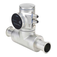
Burkert FLOWave L Operating Instructions Manual (354 pages)
SAW Flowmeter
Brand:
Burkert
| Category:
Measuring Instruments
| Size: 5 MB
Table of Contents
General Information
5
Table of Contents
5
The Operating Instructions
6
Symbols Used
6
Definition of the Term Device
6
Definition of the Term Büs
7
Validity of the Operating Instructions
7
Intended Use
8
Device with ATEX / Iecex Certification
8
Basic Safety Information
9
General Information
11
Manufacturer's Address and International Contacts
11
Warranty Conditions
11
Information on the Internet
11
Description
13
Description
14
Device Variants
14
Unlocking Magnetic Key
16
Wi-Fi Module
16
Adhesive Labels
17
Type Labels
17
Certification Markings
19
Laser Marking
19
Marking of the Unique Serial Number (USN)
19
Marking with the MAC Address
19
Device Status Indicator
20
Technical Data
21
Operating Conditions
22
Technical Data
22
Conformity to Standards and Directives
23
Conformity to the Pressure Equipment Directive
23
UL Certification
23
ATEX / Iecex Certification
24
EHEDG Certification
24
Liquid Data
25
Measurement Data
27
Temperature
27
Volume Flow Rate
27
Acoustic Transmission Factor
28
Density
28
Differentiation Factor
28
Mass Flow Rate
28
Electrical Data
29
Mechanical Data
31
Modbus TCP Protocol
32
Specifications of the Ethernet Industrial Communication
32
PROFINET Protocol
33
Ethernet/Ip Protocol
34
Ethercat Protocol
35
Installation in the Pipe
37
Installation in the Pipe
38
Safety Instructions
38
Additional Documentation
39
Changing the Position of the Transmitter on the Sensor
39
Preparing the Device before Installation into the Pipe
39
Switching Positions of the Blind Cover and the Display Module or the Wi-Fi Module
43
Recommendations for the Installation into the Pipe
46
Before Installing the Device into the Pipe
49
Installing a Device with Clamp Connections
49
Installing a Device with Flange Connections
49
Installing the Device into the Pipe
49
Installing a Device with External-Threaded Connections According to DIN 11851 Series a for Pipes According to DIN 11850
50
Electrical Installation
51
Electrical Installation
52
Safety Instructions
52
Additional Documentation
54
Connecting the Device to a Power Supply
54
Connecting the Device to a Büs / Canopen Network
55
Activating the Device Internal Termination Resistor
57
Specifications of the Cables for the M20X1.5 Cable Glands (Device Variant with Cable Glands)
57
Specifications of the Conductors for the 12 Push-In Terminal Strip
58
Terminal Assignment of the 12 Push-In Terminal Strip
58
Opening the Front of the Transmitter
59
Wiring the Device through the M20X1.5 Cable Glands in Stainless Steel (Device Variant with Cable Glands)
61
Wiring the Device through the M20X1.5 Cable Glands in Nickel Plated Brass (Device Variant with Cable Glands)
63
Connecting The Functional Earth (Device Variant With Two M20X1.5 Cable Glands)
65
Connecting the Device to a 12
65
Variant With Cable Glands)
67
Wiring Output 1 (Analogue) And Output 3 Configured As An Analogue Output
67
Wiring Output 2 (Digital) And Output 3 Configured As A Digital Output
68
With Cable Glands)
68
Knowing the Status of the Ethernet Network (Device Variant with Two 4-Pin M12 Female Connectors - Ethernet Device Variant)
69
Connecting the Device to an Ethernet Network (Device Variant with Two 4-Pin M12 Female Connectors - Ethernet Device Variant)
70
Specifications Of The Cables And Conductors For The 4-Pin M12 Female Connectors
70
Connecting the Functional Earth (Device Variant with Two 4-Pin M12 Female Connectors - Ethernet Device Variant)
71
Doing the Settings
79
Available Software To Do The Settings
80
Connect The Device To The Bürkert Communicator Software
80
How to Do the Settings
80
Safety Instructions
80
Display Module: Description Of The User Interface
82
Description of the Display
83
Available Login User Levels
84
How to Use the Touch Sensitive Keys
84
Minimum and Maximum Values When Entering a Numerical Value
84
Default Settings
85
Menu Structure
86
Opening or Closing the Context Menu in any View (Display Module Only)
87
Adding Your Own Context Menu Items (Shortcuts, Display Module Only)
88
Changing the Login User Level if the Adjustment Is Not Protected through Passwords
89
Reading out the Messages Generated by the Device
89
Changing The Login User Level If The Adjustment Is Protected Through Passwords
90
Logging out from the Advanced User, Installer or Bürkert User Level
90
Adjusting a Percentage or Selecting a Value in a List
91
How To Navigate In The Menus And To Adjust Values
91
Reading out the Access Path to a Menu Item (Display Module Only)
91
Navigating in a Wizard and Adjusting Numbers
92
Setting Negative or Positive Numbers
93
Entering a Name
94
Activating or Deactivating a Feature
95
Menu Display
97
Display Module Settings
98
Doing The Quick
98
Safety Instructions
98
Adjusting the Brightness of the Display Backlight
99
Adjusting the Contrast of the Display
99
Menu Parameter
99
Adjusting the Activation Delay of the Screen Saver
100
Adjusting the Brightness of the Backlight by Active Screen Saver
100
Changing the Unlock Sequence of the Screen Saver
101
Unlocking the Screen Saver
101
Menu Diagnostics
102
Menu Maintenance
102
Reading out the Temperature of the Display Module
102
Reading out the Version Number of the Software of the Display Module
102
Reading out the Article Number of the Display Module
103
Reading out the Version Number of the Hardware of the Display Module
103
Reading out the Article Number of the Display Module Software
104
Reading out the Serial Number of the Display Module
104
Menu General Settings
105
Default Settings
108
General Settings - Parameter
108
Safety Instructions
108
User Levels Of The Editable Menu Items
108
Changing the Operating Mode of the Device Status Indicator
109
Changing the Operating Mode of the Device Status Indicator or Switching off the Device Status Indicator
109
Switching off the Device Status Indicator
109
Entering a Name for the Device
110
Entering the Location of the Device
110
Setting The Basic Parameters For Identifying The Device On Büs
110
Entering a Description for the Device
111
Entering a Unique Name for the Device
111
Setting the Advanced Parameters for Identifying the Device Connected to Büs or to a Canopen Bus
111
Activating the Device Internal Termination Resistor
112
Changing the Transmission Speed on the Device
112
Changing the Address of the Device Connected to a Canopen Bus
113
Deactivating the Device Internal Termination Resistor
113
Setting the Digital Communication for Büs or for a Canopen Bus
114
Monitoring The Device Supply Voltage Or The Device Temperature
115
Stop Sending the Measured Process Data (Pdos) to Büs or to the Canopen Fieldbus
115
Changing the 2 Warning Limit Values
117
Reading out the 2 Error Limit Values
117
Reading out the Hysteresis Value
117
Reading Out The Low Warning Limit For The Voltage Of The Internal Battery
118
Start-Up - Doing The Basic Settings
118
Activating The Diagnostics Function
119
Configuration Provider
120
Disabling All The Diagnostics
120
Reading Out The Status Of The Configuration Provider
121
Replacing The Data Of The Configuration Memory
122
Transferring The Configuration Data Of All The Modules
122
Changing The Date And The Time
123
Changing The Display Language
123
Activating The Adjustment Protection Through Passwords
124
Changing The Protection Passwords Of The Advanced User And Installer User Levels
124
Changing The Units Of The Physical Quantities
125
Deactivating The Adjustment Protection Through Passwords
125
Displaying The Text -- (Nan) Or A Numerical Value
126
General Settings - Diagnostics
127
Reading Out Data Related To The Device
127
Reading out the Number of Operating Hours of the Device
127
User Levels Of The Menu Items
127
Reading out the Current Value of the Internal Temperature of the Device
128
Reading out the Current Value of the Supply Voltage
128
Reading out the Minimum or the Maximum Value of the Internal Temperature of the Device
128
Reading out the Current Value of the Current Consumption of the Device
129
Reading out the Minimum or the Maximum Value of the Supply Voltage
129
Reading out the Minimum or the Maximum Value of the Current Consumption of the Device
130
Reading out the Number of Device Starts
130
Reading out the Status of the Configuration Memory
130
Checking The Voltage Of The Internal Battery
131
Checking Whether The Date And Time Are Correct
131
Reading Out Data Related To Büs
132
Reading out the Maximum Number of Receive Errors Since the Last Power-Up of the Device
132
Reading out the Number of Current Receive Errors
132
Reading out the Number of Current Transmit Errors
132
Reading out the Maximum Number of Transmit Errors Since the Last Power-Up of the Device
133
Reading out Whether the Measured Process Data (PDO, Process Data Object) Is Sent on Büs or on the Canopen Fieldbus
133
Resetting the 2 Maximum Error Counters
133
Configuration Provider Information
134
Reading out the Current Status of the Configuration Provider
134
Reading out the Number of Loaded Client (Module) Configurations
135
Reading out the Number of Managed Modules
135
Reading out the Number of Reconfigured Clients (Modules)
135
Reading out the Number of Failed Configuration Loads
136
Reading out the Number of Missing Modules
136
Erasing the Configuration Data of a Single Module
137
Reading out the Number of Failed Reconfigurations
137
General Settings - Maintenance
138
Reading Out Some Device Information
138
Reading out the Article Number of the Device
138
Reading out the Displayed Name of the Device
138
User Levels Of The Menu Items
138
Reading out the Article Number of the Device Software
139
Reading out the Serial Number of the Device
139
Reading out the Version Number of the Device Software
139
Reading out the Type Number of the Device
140
Reading out the Version Number of the Büs Software
140
Reading out the Version Number of the Device Hardware
140
Reading Out The Version Of The Embedded Eds File
141
Reading out the Manufacturing Date of the Device
141
Resetting The Device
142
Resetting the Device to All Its Factory Settings
142
Restarting the Device
142
Updating the Menu Configuration of the Device
143
Menu - Saw Sensor Parameter
145
Default Settings
150
Safety Instructions
150
Saw Sensor - Parameter
150
User Levels Of The Editable Menu Items
150
Activating the Damping of the Volume Flow Rate Values and Choosing a Predefined Damping Level
151
Giving a User Defined Name to the Measured Volume Flow Rate
151
Setting The Parameters Of The Volume Flow Rate
151
Activating a User-Defined Damping of the Volume Flow Rate Values
153
Activating the Monitoring of the Volume Flow Rate
154
Deactivating the Damping of the Volume Flow Rate Values
154
Deactivating the Monitoring of the Volume Flow Rate
156
Changing the Error Limits, the Warning Limits and the Hysteresis of the Volume Flow Rate
157
Resetting the Default Values of the Error Limits, the Warning Limits and the Hysteresis of the Volume Flow Rate
158
Enabling the Cut-Off Function of the Volume Flow Rate
159
Changing The Cut-Off Value Of The Volume Flow Rate
160
Disabling The Cut-Off Function Of The Volume Flow Rate
160
Resetting The Default Values Of All The Volume Flow Rate Parameters
161
Activating the Damping of the Mass Flow Rate Values and Choosing a Predefined Damping Level
162
Giving a User Defined Name to the Measured Mass Flow Rate
162
Setting The Parameters Of The Mass Flow Rate
162
Activating a User-Defined Damping of the Mass Flow Rate Values
165
Activating the Monitoring of the Mass Flow Rate
166
Deactivating the Damping of the Mass Flow Rate Values
166
Deactivating the Monitoring of the Mass Flow Rate
168
Changing the Error Limits, the Warning Limits and the Hysteresis of the Mass Flow Rate
169
Resetting the Default Values of the Error Limits, the Warning Limits and the Hysteresis of the Mass Flow Rate
169
Enabling the Cut-Off Function of the Mass Flow Rate
170
Changing The Cut-Off Value Of The Mass Flow Rate
171
Disabling The Cut-Off Function Of The Mass Flow Rate
172
Resetting The Default Values Of All The Mass Flow Rate Parameters
172
Activating the Damping of the Liquid Temperature Values and Choosing a Predefined Damping Level
173
Giving a User Defined Name to the Measured Liquid Temperature
173
Setting The Parameters Of The Liquid Temperature
173
Activating a User-Defined Damping of the Liquid Temperature Values
175
Activating the Monitoring of the Liquid Temperature
176
Deactivating the Damping of the Liquid Temperature Values
176
Deactivating the Monitoring of the Liquid Temperature
177
Changing the Error Limits, the Warning Limits and the Hysteresis of the Liquid Temperature
178
Resetting the Default Values of the Error Limits, the Warning Limits and the Hysteresis of the Liquid Temperature
178
Resetting the Default Values of All the Liquid Temperature Parameters
179
Giving a User Defined Name to the Measured Liquid Concentration
180
Selecting the Liquid Concentration Type
180
Setting The Parameters Of The Liquid Concentration
180
Activating the Damping of the Liquid Concentration Values and Choosing a Predefined Damping Level
181
Activating a User-Defined Damping of the Liquid Concentration Values
182
Activating the Monitoring of the Liquid Concentration
183
Deactivating the Damping of the Liquid Concentration Values
183
Deactivating the Monitoring of the Liquid Concentration
184
Changing the Error Limits, the Warning Limits and the Hysteresis of the Liquid Concentration
185
Resetting The Default Values Of All The Liquid Concentration Parameters
186
Resetting the Default Values of the Error Limits, the Warning Limits and the Hysteresis of the Liquid Concentration
186
Activating the Damping of the Liquid Velocity Values and Choosing a Predefined Damping Level
187
Giving a User Defined Name to the Measured Liquid Velocity
187
Setting The Parameters Of The Liquid Velocity
187
Activating a User-Defined Damping of the Liquid Velocity Values
189
Activating the Monitoring of the Liquid Velocity
190
Deactivating the Damping of the Liquid Velocity Values
190
Deactivating the Monitoring of the Liquid Velocity
191
Changing the Error Limits, the Warning Limits and the Hysteresis of the Liquid Velocity
192
Resetting the Default Values of the Error Limits, the Warning Limits and the Hysteresis of the Liquid Velocity
192
Resetting The Default Values Of All The Liquid Velocity Parameters
193
Activating the Damping of the Liquid Density Values and Choosing a Predefined Damping Level
194
Giving a User Defined Name to the Measured Liquid Density
194
Setting The Parameters Of The Liquid Density
194
Activating a User-Defined Damping of the Liquid Density Values
196
Activating the Monitoring of the Liquid Density
197
Deactivating the Damping of the Liquid Density Values
197
Deactivating the Monitoring of the Liquid Density
198
Changing the Error Limits, the Warning Limits and the Hysteresis of the Liquid Density
199
Resetting the Default Values of the Error Limits, the Warning Limits and the Hysteresis of the Liquid Density
199
Setting the Measurement Mode of Liquid Density
200
Resetting The Default Values Of All The Liquid Density Parameters
201
Choosing The Counting Direction Of Each Volume Totalizer
202
Giving A User Defined Name To Each Volume Totalizer
202
Setting The Parameters Of The Volume Totalizers
202
Activating The Monitoring Of Each Volume Totalizer Value
203
Changing The Error Limits, The Warning Limits And The Hysteresis Of Each
204
Deactivating The Monitoring Of Each Volume Totalizer
204
Volume Totalizer
204
Enabling The User To Start, Stop Or Reset Each Volume Totalizer
205
Resetting the Default Values of the Error Limits, the Warning Limits and the Hysteresis of each Volume Totalizer
205
Disabling The User To Start, Stop Or Reset Each Volume Totalizer
206
Starting Each Volume Totalizer
206
Stopping Each Volume Totalizer
206
Changing The Preset Value For A Volume Totalizer Reset
207
Resetting each Volume Totalizer to a Preset Value
207
Giving A User Defined Name To Each Mass Totalizer
208
Resetting All The Parameters Of Each Volume Totalizer To Their Default Values
208
Resetting The Overflow Counter Of Each Volume Totalizer
208
Setting The Parameters Of The Mass Totalizers
208
Choosing The Counting Direction Of Each Mass Totalizer
209
Activating The Monitoring Of Each Mass Totalizer Value
210
Changing the Error Limits, the Warning Limits and the Hysteresis of each Mass Totalizer
211
Deactivating The Monitoring Of Each Mass Totalizer
211
Enabling The User To Start, Stop Or Reset Each Mass Totalizer
212
Resetting the Default Values of the Error Limits, the Warning Limits and the Hysteresis of each Mass Totalizer
212
Disabling The User To Start, Stop Or Reset Each Mass Totalizer
213
Starting Each Mass Totalizer
213
Stopping Each Mass Totalizer
213
Changing The Preset Value For A Mass Totalizer Reset
214
Resetting each Mass Totalizer to a Preset Value
214
Resetting All The Parameters Of Each Mass Totalizer To Their Default Values
215
Resetting The Overflow Counter Of Each Mass Totalizer
215
Giving A User Defined Name To The Measured Differentiation Factor
216
Setting The Parameters Of The Differentiation Factor (Optional Feature)
216
What Is The Differentiation Factor
216
Activating the Damping of the Differentiation Factor Values and Choosing a Predefined Damping Level
217
Activating A User-Defined Damping Of The Differentiation Factor Values
218
Deactivating The Damping Of The Differentiation Factor Values
219
Activating The Monitoring Of The Differentiation Factor
220
Deactivating The Monitoring Of The Differentiation Factor
220
Changing the Error Limits, the Warning Limits and the Hysteresis of the Differentiation Factor
221
Resetting the Default Values of the Error Limits, the Warning Limits and the Hysteresis of the Differentiation Factor
222
Setting The Temperature Compensation For A Liquid Other Than Water
223
Setting The Temperature Compensation To Measure The Differentiation Factor
223
Activating The Temperature Compensation For Water
224
Resetting The Default Values Of All The Differentiation Factor Parameters
225
Use Case Example Of The Differentiation Factor
225
Giving A User Defined Name To The Measured Acoustic Transmission Factor
226
Setting The Parameters Of The Acoustic Transmission Factor (Optional Feature)
226
What Is The Acoustic Transmission Factor
226
Activating the Damping of the Values of the Acoustic Transmission Factor and Choosing a Predefined Damping Level
227
Activating a User-Defined Damping of the Values of the Acoustic Transmission Factor
229
Changing the Error Limits, the Warning Limits and the Hysteresis of the Acoustic Transmission Factor
230
Deactivating The Damping Of The Values Of The Acoustic Transmission
230
Activating The Monitoring Of The Acoustic Transmission Factor
231
Deactivating The Monitoring Of The Acoustic Transmission Factor
232
Resetting the Default Values of the Error Limits, the Warning Limits and the Hysteresis of the Acoustic Transmission Factor
232
Diagnostics: Monitoring Special Events that Occur in the Process, on the Sensor or on the Electronics
233
Resetting The Default Values Of All The Acoustic Transmission Factor Parameters
233
Enabling The Diagnostics For Special Events In The Process
237
Disabling The Diagnostics On A Special Event Occurring On The Electronics
238
Disabling The Diagnostics On A Special Event Related To The Process
238
Disabling The Diagnostics On A Special Event Occurring On The Sensor
239
Enabling The Diagnostics For Special Events Occurring On The Electronics
239
Enabling The Diagnostics For Special Events Occurring On The Sensor
240
Getting as Accurate Measurements of the Volume Flow Rate, the Mass Flow Rate or the Liquid Velocity as Possible
241
Activating The Compensation For A Liquid With A Constant Viscosity
242
Activating The Viscosity Compensation For Water-Like Liquids
242
Activating the Compensation for a Liquid with a Linear Viscosity Compensation Curve
243
Activating the Compensation for a Liquid with a Quadratic Viscosity Compensation Curve
244
Activating the Compensation for a Liquid with an Inverse Quadratic Viscosity Compensation Curve
245
Resetting The Default Values Of The Viscosity Compensation Parameters
246
Changing The Refresh Time
247
Setting The Refresh Time
247
Use Case Of The Refresh Time
247
Menu -Saw Sensor Diagnostics
249
Reading Out The Flow Direction That Has Been Set
250
Reading Out The Generated Events Related To The Device
250
Reading Out The Temperatures Of The Electronic Boards And Of The Liquid
250
Saw Sensor - Diagnostics
250
Reading Out The Operating Hours Of The Device
251
Reading Out The Refresh Time That Has Been Set
251
Reading Out The Diagnostics Events That Occurred In The Process
252
Reading Out The Diagnostics Related To The Output Values
252
Reading Out The Operating Hours Of The Measurement Board
252
Reading Out The Diagnostics Events That Occurred On The Electronics
253
Reading Out The Diagnostics Events That Occurred On The Sensor
253
Reading Out If A Process Value Is In The Monitored Range
254
Reading Out The Diagnostic Events Related To The Monitored Limits
254
Menu - Saw Sensor Maintenance
255
Default Settings
257
Reading Out Some Device Information
257
Reading out the Ordering Codes of the Device, the Transmitter Board and the Measurement Board
257
Saw Sensor - Maintenance
257
User Levels Of The Editable Menu Items
257
Reading out the Characteristics of the Measurement Tube
258
Reading out the Hardware and Software Versions of the Transmitter Board and of the Measurement Board
258
Reading out the Serial Numbers of the Device, the Transmitter Board and the Measurement Board
258
Checking the Correct Operation of the Sensor
259
Reading out the Calibration Date at the Manufacturer
260
Reading out the Liquid Type and the Liquid Temperature During Calibration at the Manufacturer
261
Reading out the Raw Measured Value of the Volume Flow Rate
261
Calibrating The Offset Value Of The Flow Zero Point
262
Setting The Direction Of The Flow
262
Setting The Offset Value Of The Flow Zero Point
263
Calibrating The K Factor By Using A Teach-In Procedure
264
Setting The K Factor
264
Calibrating the K Factor by Using a Teach-In Procedure Depending on the Volume Flow Rate
265
Calibrating the K Factor by Using a Teach-In Procedure Depending on a Known Volume
266
Calibrating the K Factor by Using a Teach-In Procedure Depending on the Mass Flow Rate
267
Calibrating the K Factor by Using a Teach-In Procedure Depending on a Known Mass
268
Resetting The Flow Rate Calibration Data To Its Default Values
270
Setting The Offset Value Of The Liquid Temperature
270
Calibrating The Offset Value Of The Liquid Temperature
271
Resetting All The Calibration Data To Its Default Values (Standard Measurement Values)
272
Resetting The Offset Of The Liquid Temperature To Its Default Value
272
Calibrating The Offset Value Of The Differentiation Factor
273
Setting The Offset Value Of The Differentiation Factor
273
Setting The Slope Value Of The Differentiation Factor
274
Setting The Offset Value Of The Liquid Density
275
Setting The Slope Value Of The Liquid Density
275
Calibrating The Liquid Density By Using A Teach-In Procedure Depending On Density
276
Setting The Offset Value Of The Liquid Concentration
276
Calibrating The Offset Value Of The Liquid Concentration
277
Setting The Slope Value Of The Liquid Concentration
278
Calibrating The Offset Value Of The Acoustic Transmission Factor
279
Setting The Offset Value Of The Acoustic Transmission Factor
279
Setting The Slope Value Of The Acoustic Transmission Factor
281
Resetting All The Calibration Data To Its Default Values (Additional Measurement Values)
282
Checking The Correct Behaviour Of The Device
283
Choosing The Process Values To Be Simulated
283
Checking The Behaviour Of The Device By Simulating An Event
284
Stopping The Simulation Of Process Values And Events
285
Menu Outputs
287
Changing The Type Of Output 3
288
Default Settings
288
Outputs - Parameter
288
Changing the Process Value and the Process Value Range Associated to an Analogue Output
289
Setting The Parameters Of An Analogue Output
289
Choosing the Damping Level of the Values Transmitted on an Analogue Output
290
Configuring the Behaviour of an Analogue Output Depending on the Status of the Device
291
Disabling An Analogue Output
292
Setting The Parameters Of A Digital Output
292
Configuring a Digital Output as an On/Off Output
293
Configuring a Digital Output as an Output with Switching Thresholds
294
Configuring a Digital Output as a Frequency Output
295
Configuring a Digital Output as a Pulse Output
296
Resetting All The Parameters Of All The Outputs To Their Default Values
298
Resetting All The Parameters Of An Output To Their Default Values
298
Analogue Output: Reading Out The Current Status And The Values Of The Current
299
Digital Output: Reading Out The Mode, The Current Status And The Current Value
299
Outputs - Diagnostics
299
Calibrating An Analogue Output
300
Checking The Correct Operation Of An Analogue Output
300
Outputs - Maintenance
300
Resetting The Calibration Data Of All The Analogue Outputs To Its Default Values
301
Resetting The Calibration Data Of An Analogue Output To Its Default Values
301
Checking The Correct Operation Of A Frequency Output
302
Checking The Correct Operation Of An On/Off Output Or A Threshold Output
302
Checking The Correct Operation Of A Pulse Output
303
Menu Industrial Communication
305
Choosing the Communication Protocol
306
Default Settings And Information On Configuration Files
306
Industrial Protocol Settings
306
Menu Parameter
306
Reading out the MAC Address of the Device
306
Changing the Network Mask
307
Changing the Static IP Address
307
Changing the Address of the Default Gateway
308
Choosing the Internal Cycle Time
308
Reading out the IP Address Assigned by a DHCP
308
Choosing the Communication Timeout and Enabling It
309
Disabling the Communication Timeout
309
Menu Maintenance
310
Reading Out The Article Number Of The Device
310
Reading Out The Hardware Version Number
310
Reading Out The Software Version Number
310
Reading Out Stack Information
311
Reading Out The Article Number Of The Software
311
Reading Out The Serial Number Of The Device
311
Reading Out The Version Of The Industrial Communication
312
Restarting The Current Industrial Communication
312
Resetting The Industrial Communication Module
313
Restoring The Configuration File
313
Menu Diagnostics
314
Reading Out The Active Protocol And The Internal Cycle Time
314
Reading Out The Number Of Ethernet Connections
314
Reading Out The Internal Temperature Of The Industrial Communication Module
315
Reading Out The Last Status Code
315
Troubleshooting, Maintenance, Transport, Storage
317
Maintenance and Troubleshooting
320
Safety Instructions
320
Cleaning In Place (Cip) Of The Device
321
Cleaning The Outer Surface Of The Device
321
Information On Returning The Device To The Manufacturer Or To The Reseller
321
Sterilisation In Place (Sip) Of The Device
322
Troubleshooting When A Message Is Displayed
323
Troubleshooting When No Message Is Displayed
323
Kinematic Viscosity ≤ 0. Check the Flow Viscosity Compensation's Parameters
324
Message "Overvoltage Detected
324
Messages Due To Device Internal Diagnostics
324
Messages When Setting Wrong Parameters
324
Message "Undervoltage Detected
325
Message "Voltage Is above the Warning Limit
325
Message "Voltage Is below the Warning Limit
325
Message "Battery Voltage Is below the Warning Limit
326
Message "Büs Event: Bus Connection Lost / Not Available
326
Message "Overtemperature Detected
326
Message "Temperature Is Below The Warning Limit
327
Message "Temperature Is above the Warning Limit
327
Message "Undertemperature Detected
327
Message "Internal Message Store Overflow
328
Message "No Signals From Interdigital Transducer
328
Message "No Temperature Sensor Detected
328
Message "Pipe Characteristics Have Changed: Check Limits Values
328
Message "Measure Board Is In Boot Starter Mode, No Firmware Found N°1
329
Message "Measured Values Cannot Be Used
329
Message "The Measurement Board Bootloader Operation Failed N° 1
329
Message "Communication between Transmitter PCB and Measurement PCB Has Been Interrupted N°X
329
Message "An Error Occurred During Communication
330
Message "Max Temperature
330
Message "Max. Flow Rate
330
Message "Totalizer 1 Stopped" / "Totalizer 2 Stopped" Or "Mass Totali
330
Zer 1 Stopped" / "Mass Totalizer 2 Stopped
330
Message "Calibration Result Out Of Range
331
Message "Totalizer 1 Started" / "Totalizer 2 Started" or "Mass Totalizer 1 Started" / "Mass Totalizer 2 Started
331
Message "Zero Calibration Cancelled, the Flow Rate Is Higher than 5 % of Full Scale
331
Messages Due To Calibration Or Simulation
331
Message "Calibration Cancelled
332
Message "Calibration Cancelled, The Flow Rate Is Less Than 5 % Of The Full
332
Message "Resulting K Factor Is Less Than 0.8 Or Higher Than 1.2
332
Message "Resulting Offset Is Higher Than 10 °C, 18 °F
332
Scale
332
Message "Flow Rate Too High
333
Message "Simulation Mode Active
333
Message "Test Mode Activated
333
Messages Due To The Monitoring Of Process Values
333
Message "Flow Rate Too Low
334
Message "Temperature Too High
334
Mass Totalizer 1 Too High" / "Value Mass Totalizer 2 Too High
335
Message "Temperature Too Low
335
Message "Value Totalizer 1 Too High" / "Value Totalizer 2 Too High" Or "Value
335
Message "Fluid Velocity Too High
336
Message "Value Totalizer 1 too Low" / "Value Totalizer 2 too Low" or "Value Mass Totalizer 1 too Low" / "Value Mass Totalizer 2 too Low
336
Message "Df Too High
337
Message "Fluid Velocity Too Low
337
Message "Acoustic Transmission Factor Too High
338
Message "Df Too Low
338
Message "Acoustic Transmission Factor Too Low
339
Message "Density Too High
339
Message "Concentration 1 Too High" / "Concentration 2 Too High
340
Message "Density Too Low
340
Message "Concentration 1 Too Low" / "Concentration 2 Too Low
341
Message "Diagnostic Is Active
341
Message "Diagnostic Is Inactive
341
Messages Due To Diagnostics Events
341
Message "Liquid Out Of Range
342
Message "Not Totally Filled
342
Message "Unstable Flow Rate
342
Message "Backward Flow
343
Message "Change Of Liquid
343
Message "Low Flow Cut Off
343
Message "Ao1 Diag Error" Or "Ao3 Diag Error
344
Message "Ao1 Open Loop" Or "Ao3 Open Loop
344
Message "Sound Conductivity Out Of Range
344
Message "Do2 Overload" Or "Do3 Overload
345
Message "No Proper Connection To The Process Control System
345
Messages Due To The Industrial Communication Module
345
Message "Cyclic Data Transfer Has Been Slower Than Configured Timeout
346
Message "Master Tried To Plug Wrong Module Or Submodule
346
Message "No Or Incorrect Mapping File Available
346
Message "Please Select A Protocol And Restart The Device
346
Message "Fieldbus Master Is Running In Stop Mode
347
Message "Initialization Of Industrial Communication
347
Spare Parts and Accessories
348
Disposal of the Device
349
Packaging, Transport
349
Storage
349
Advertisement
Advertisement
Related Products
Burkert FLOWave S
Burkert 285877
Burkert 285880
Burkert 286100
Burkert 286212
Burkert 2875
Burkert 287586
Burkert 288026
Burkert 288078
Burkert 292193
Burkert Categories
Control Unit
Controller
Measuring Instruments
Transmitter
Accessories
More Burkert Manuals
Login
Sign In
OR
Sign in with Facebook
Sign in with Google
Upload manual
Upload from disk
Upload from URL