Burkert ELEMENT 8222 Operating Instructions Manual
Conductivity meter
Hide thumbs
Also See for ELEMENT 8222:
- Operating instructions manual (110 pages) ,
- Quick start manual (118 pages) ,
- Operating instructions manual (74 pages)

Related Manuals for Burkert ELEMENT 8222


Summary of Contents for Burkert ELEMENT 8222
- Page 1 Type 8222 ELEMENT Conductivity meter Leitfähigkeits-Messgerät Conductivimètre Operating Instructions Bedienungsanleitung Manuel d‘utilisation...
- Page 2 We reserve the right to make technical changes without notice. Technische Änderungen vorbehalten. Sous réserve de modifications techniques. © Bürkert SAS, 2008 - 2021 Operating Instructions 2106/6_EU-ML 00560330 / Original_FR...
-
Page 3: Table Of Contents
Type 8222 ELEMENT Contents About the operAting instructions ..........................6 1.1 Definition of the word “device” ............................6 1.2 Validity of the operating instructions ........................6 1.3 symbols used ..................................6 intenDeD use ....................................7 bAsic sAfety informAtion ..............................7 generAl informAtion ................................9 4.1 contact .......................................9 4.2 Warranty conditions ................................9 4.3 information on the internet .............................9 Description ....................................10 5.1 Area of application ................................10 5.2 construction of the 8222 ...............................10 5.3 conductivity sensor . - Page 4 Type 8222 ELEMENT 7.3 mounting the housing lid ..............................20 7.4 mounting the display module .............................20 7.5 Dismounting the display module ..........................21 instAllAtion AnD Wiring ..............................22 8.1 safety instructions ................................22 8.2 installing a device on the pipe ...........................23 8.3 Wiring .......................................25 8.3.1 Assembling the male or female connector (accessories) ............25 8.3.2 Making the installation equipotential ....................26 8.3.3 Wiring a device variant with a single M12 fixed connector .............27 8.3.4 Wiring a device variant with 2 M12 fixed connectors ..............29 ADjustment AnD stArt-up ..............................32...
- Page 5 Type 8222 ELEMENT 9.11.8 Choosing the output wiring mode ....................47 9.11.9 Setting the parameters of the current outputs ................47 9.11.10 Setting the parameters of the transistor outputs ...............49 9.11.11 Choosing the type of temperature compensation ..............50 9.12 Knowing the calibration menu ...........................51 9.12.1 Activating/deactivating the Hold function ..................51 9.12.2 Modifying the Calibration menu access code ................52...
-
Page 6: About The Operating Instructions
Type 8222 ELEMENT AbouttheOperatingInstructions AbouT ThE opErATiNg iNsTrucTioNs The Operating Instructions describe the entire lifecycle of the device. Please keep the Operating Instructions in a safe place, accessible to all users and any new owners. the operating instructions contains important safety information. Failure to comply with these instructions can lead to hazardous situations. ▶... -
Page 7: Intended Use
Type 8222 ELEMENT AbouttheOperatingInstructions ▶ Indicates an instruction for risk prevention. → Indicates a work step that you must carry out. Indicates a result. iNTENDED usE use of the device that does not comply with the instructions could present risks to people, nearby installations and the environment. The Type 8222 ELEMENT conductivity meter is intended for the measurement of the conductivity in liquids ▶... - Page 8 ▶ Do not use the device in an environment incompatible with the device materials. ▶ Do not use fluid that is incompatible with the device materials. Find the compatibility chart on our homepage: country.burkert.com ▶ Do not subject the device to mechanical stress.
-
Page 9: General Information
Rue du Giessen BP 21 F-67220 TRIEMBACH-AU-VAL The addresses of our international sales offices are available on the internet at: country.burkert.com 4.2 Warranty conditions The condition governing the legal warranty is the conforming use of the device in observance of the operating conditions specified in the Operating Instructions. -
Page 10: Description
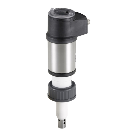
Type 8222 ELEMENT Description DEscripTioN 5.1 Area of application The Type 8222 ELEMENT conductivity meter is intended for the measurement of the conductivity. Thanks to two fully adjustable transistor outputs, the device can be used to switch a solenoid valve, activate an alarm and, thanks to one or two 4...20 mA current outputs, establish one or two control loops. 5.2 construction of the 8222 The device comprises:... -
Page 11: Type Label
Type 8222 ELEMENT Description 5.4 Type label 8222 Conductivity Transmitter Supply: 14-36V 40W Max. Output: 1x 4-20mA 2x Trans. 1A Max Cell: C 1,00 Range 5-10000 µS/cm Process: Temp:0...+50°C, PN 16 Bar Limited by cell and materials fitting W41MT IP65 -IP67 2:NPN/PNP1 3:0V 1:V+ S-N:2691 4:NPN/PNP2... -
Page 12: Technical Data
Type 8222 ELEMENT Technicaldata TEchNicAL DATA 6.1 conditions of use Ambient temperature –10...+60 °C Air humidity < 85%, without condensation Indoor and outdoor ▶ Protect the device against electromagnetic interference, ultravio- let rays and, when installed outdoors, the effects of the climatic conditions. ip-code IP67 and IP65 according to IEC / EN 60529 Mating connectors must be wired, plugged, and tightened. -
Page 13: Ul Certification
• UL 61010-1 • CAN/CSA-C22.2 n°61010-1 identification on the device certification Variable key UL recognized PU01 Measuring UL listed PU02 Equipment ® EXXXXXX 6.3 Dimensions of the device → Please refer to the technical data sheets related to the device available at: country.burkert.com English... -
Page 14: Mechanical Data
Type 8222 ELEMENT Technicaldata 6.4 Mechanical data part material Nickel-plated Housing stainless steel 316L brass Silicone 1.4404, PPS (or stainless Housing seals EPDM steel) Housing lid Housing-lid seal silicone PPS CF30 EPDM Display module PC, PBT Stainless steel M12 male connector, • nickel-plated brass M12 female connector •... -
Page 15: Fluid Data
Type 8222 ELEMENT Technicaldata 6.5 fluid data pipe diameter DN25 to DN110 (DN15 to DN20 under specific conditions) type of fitting Type S022 nut between the 8222 and the fitting G 1 1/2'' internal thread fluid temperature The fluid temperature may be restricted by the fluid pressure, the material of the nut and the material of the fitting used. - Page 16 Type 8222 ELEMENT Technicaldata • A: application range of a 8222 with a PVDF nut P (bar) P (psi) • B: application range of a 8222 with a PVC nut 217.6 PVDF The measures have been made at an ambient tem- 188.6 perature of 60 °C 159.6 PVDF...
-
Page 17: Electrical Data
Type 8222 ELEMENT Technicaldata 6.6 Electrical data operating voltage • Device variant with 3 outputs • 14...36 V DC • connection to main supply: permanent through external safety extra- low voltage (SELV) and through limited power source (LPS) • filtered and regulated • Device variant with 4 outputs •... -
Page 18: Sensor Specifications
Type 8222 ELEMENT Technicaldata 6.7 sensor specifications conductivity sensor c=0.01 • Measurement range • 0.05...20 µS/cm • Type of fluid • ultra-pure water, pure water conductivity sensor c=0.1 • Measurement range • 0.5...200 µS/cm • pure water, industrial wastewater • Type of fluid conductivity sensor c=1 • Measurement range •... -
Page 19: Assembly
Type 8222 ELEMENT Assembly AssEMbLy 7.1 safety instructions Warning risk of injury due to non-conforming assembly. ▶ The device must only be assembled by qualified and skilled staff with the appropriate tools. risk of injury due to unintentional switch on of power supply or uncontrolled restart of the installation. ▶ Avoid unintentional activation of the installation. ▶ Guarantee a defined or controlled restart of the process subsequent to any intervention on the device. 7.2 removing the housing lid notice... -
Page 20: Mounting The Housing Lid
Type 8222 ELEMENT Assembly 7.3 Mounting the housing lid → Check that there is a seal on the housing and that it is not damaged. Replace the seal if necessary. → Grease the seal if necessary, using a component compatible with the seal material. → [1] Set the housing lid to ensure that the 4 grooves of the housing lid match with the 4 pins of the housing. -
Page 21: Dismounting The Display Module
Type 8222 ELEMENT Assembly 7.5 Dismounting the display module → Remove the housing lid if necessary. Refer to chpt. 7.2. → Turn the module by ca. 20° counterclockwise. Once unlocked, the display module is raised slightly by the spring action. 20° → Remove the display module from its housing. Fig. 9 : ... -
Page 22: Installation And Wiring
Type 8222 ELEMENT Installationandwiring iNsTALLATioN AND WiriNg 8.1 safety instructions risk of injury due to electrical voltage. ▶ Before carrying out work on the system or the device, disconnect the electrical power for all the conductors and isolate it. ▶ If the device is installed either in a wet environment or outdoors, all the electrical voltages must be of max. 35 V DC. -
Page 23: Installing A Device On The Pipe
Type 8222 ELEMENT Installationandwiring 8.2 installing a device on the pipe danger risk of injury due to pressure in the installation. ▶ Before any intervention in the installation, stop the circulation of fluid, cut off the pressure and drain the pipe. ▶ Before any intervention in the installation, make sure that there is no pressure in the pipe. risk of injury due to the nature of the fluid. - Page 24 Type 8222 ELEMENT Installationandwiring → Mount the device into the fitting, as shown in Fig. 11: → Check that seal "A" is set on the fitting and that it is not damaged. Replace the seal if necessary. → Carefully insert the device into the fitting. →...
-
Page 25: Wiring
Type 8222 ELEMENT Installationandwiring 8.3 Wiring danger risk of injury due to electrical voltage. ▶ Before carrying out work on the system or the device, disconnect the electrical power for all the conductors and isolate it. ▶ If the device is installed either in a wet environment or outdoors, all the electrical voltages must be of max. 35 V DC. -
Page 26: Making The Installation Equipotential
Type 8222 ELEMENT Installationandwiring 8.3.2 Making the installation equipotential To ensure the equipotentiality of the installation (power supply - device - medium): → Connect together the various earth spots in the installation to eliminate the potential differences that may occur between different earthes. → Observe faultless grounding of the shield of the power supply cable. Refer to Fig. 13 and Fig. 14. →... -
Page 27: Wiring A Device Variant With A Single M12 Fixed Connector
Type 8222 ELEMENT Installationandwiring 8.3.3 Wiring a device variant with a single M12 fixed connector Transistor output 1 V+ (14...36 V DC) Transistor output 2 Fig. 15 : Pin assignment of the male fixed connector on a device variant with a single male M12 fixed connector pin of the m12 female cable available as an accessory (article number 438680) colour of the wire brown white blue black green/yellow or grey Load 1 (solenoid valve for instance) white brown black green/yellow or grey Load 2 blue (solenoid valve for instance) Power supply 14-36 V DC... - Page 28 Type 8222 ELEMENT Installationandwiring 4...20 mA input at external 4...20 mA input at external device device blue brown brown green/yellow green/yellow or grey or grey blue Power supply Power supply 14-36 V DC 14-36 V DC Fig. 18 : Possible connections of the current output (whatever the software setting, «NPN/sink» or «PNP/source», see chpt. 9.11.8), on a device variant with 1 fixed connector 4...20 mA input at external device Load 1 white brown...
-
Page 29: Wiring A Device Variant With 2 M12 Fixed Connectors
Type 8222 ELEMENT Installationandwiring 8.3.4 Wiring a device variant with 2 M12 fixed connectors male fixed connector female fixed connector Transistor output 1 Transistor output 2 (12...36 V DC) (12...36 V DC) Current output 2 Current output 1 Fig. 21 : Pin assignment of the male and female M12 fixed connectors Connect the power supply for the device to the male fixed connector; the supply is then transferred inter- nally to pins 1 and 3 of the female fixed connector in order to ease wiring of the load to the female fixed connector. - Page 30 Type 8222 ELEMENT Installationandwiring Load 2 (solenoid valve for instance) Load 1 (solenoid valve for instance) white white brown blue blue green/yellow or grey Power supply 12-36 V DC Fig. 23 : PNP wiring of both transistor outputs (software setting „PNP/source“, see chpt. 9.11.8), on a device variant with 2 fixed connectors First 4...20 mA input at Second 4...20 mA input at external device external device brown...
- Page 31 Type 8222 ELEMENT Installationandwiring Load 1 Load 2 white white blue brown brown green/yel- black low or grey black 4...20 mA input at external 4...20 mA input at external device device 12-36 V DC Power supply Fig. 26 : NPN wiring of both transistor outputs and wiring of both current outputs in sinking mode, on a device variant with 2 fixed connectors (software setting «NPN/sink», see chpt. 9.11.8) Load 1 Load 2 white white blue...
-
Page 32: Adjustment And Start-Up
Type 8222 ELEMENT Adjustmentandstart-up ADjusTMENT AND sTArT-up • The settings can only be done on a device with a display module. • Do not remove the display module while making the settings on the device. 9.1 safety instructions Warning risk of injury due to non-conforming adjustment. Non-conforming adjustment could lead to injuries and damage the device and its surroundings. ▶... -
Page 33: Using The Navigation Button
Type 8222 ELEMENT Adjustmentandstart-up configuration level This level comprises 5 menus: menu title related icon "Param": see chpt. 9.11. This is when the device is be- ing parame- tered........ "Calib": see chpt. 9.12. "Diagnostic": see chpt. 9.13. "Test": see chpt. 9.14. "Info": see chpt. 9.15. 9.3 using the navigation button Symbolised by... - Page 34 Type 8222 ELEMENT Adjustmentandstart-up you want to... press..browse in Process level • next screen: • previous screen: • ...access the Configuration level • ...display the Param menu for at least 2 sec., from any screen of the Process level ...browse in the menus of the Configuration level •...
-
Page 35: Using The Dynamic Functions
Type 8222 ELEMENT Adjustmentandstart-up 9.4 using the dynamic functions you want to... choose..go back to the Process level, without validating the modifications made dynamic function "MEAS" ...validate the input dynamic function "OK" ...go back to the parent menu dynamic function "BACK" ... abort the current operation and go back to the parent menu dynamic function "ABORT"... -
Page 36: Knowing The Display
Type 8222 ELEMENT Adjustmentandstart-up 9.7 Knowing the display The display module is only equipped on some device variants of the device. It can be ordered as an accessory. 9.7.1 Knowing the icons and LEDs Yellow LED: shows that Green LED: shows that transistor 1 is switched the device is energized conds 0.000 µs/cm tempc... -
Page 37: Knowing The Display At The Power-Up Of The Device
Type 8222 ELEMENT Adjustmentandstart-up 9.7.2 Knowing the display at the power-up of the device When the device is powered up or the display module mounted on the electronic module, the display indicates the software version of the display module. The display then shows the first screen of the Process level: See chpt. -
Page 38: Accessing The Configuration Level
Type 8222 ELEMENT Adjustmentandstart-up 9.9 Accessing the configuration level > 2s Param This is This is when the when the This is Any display of the when the device is be- device is be- ing parame- ing parame- device is be- tered.... tered............ System ing parame- tered.... -
Page 39: Knowing The Structure Of The Menus On The Configuration Level
Type 8222 ELEMENT Adjustmentandstart-up 9.10 Knowing the structure of the menus on the configuration level See chpt. 9.9 to access the Configuration level. If an “upload” has been done with this display Param System Up/Download Download Downl. Yes/No module Upload Upload Yes/No This is This is when the when the device is be- device is be- ing parame-... - Page 40 Type 8222 ELEMENT Adjustmentandstart-up Param Outputs HWMode sink/NPN source/PNP This is This is when the when the device is be- device is be- ing parame- ing parame- tered.... tered............ PVar: CondS AC1/AC2 CondR TempC TempF TDSppm INPUT 4mA: 20mA: INPUT Filter: None Fast...
- Page 41 Type 8222 ELEMENT Adjustmentandstart-up Calib RESULT Sensor Probe Calibration INPUT INPUT Cell constant Cell cst. TDS INPUT Calib interval Last cal. date READ Interval INPUT Teach special Start temp INPUT Stop temp INPUT Processing Temperature INPUT Diagnostic System Code 0*** Confirm code 0*** Sensor Conductivity...
-
Page 42: Knowing The Parameters Menu
Type 8222 ELEMENT Adjustmentandstart-up Test System Code 0*** Confirm code 0*** Outputs AC1: INPUT AC2: INPUT TR1: OFF/ON TR2: OFF/ON Sensor PVar: CondS CondR TempC TempF TDSppm INPUT Value: Info Error MESSAGE Warning MESSAGE Mainten. MESSAGE Smiley MESSAGE Software Main READ READ Sensor Product MESSAGE... -
Page 43: Setting The Date And Time
Type 8222 ELEMENT Adjustmentandstart-up Param System Up/Download Download Downl. Yes/No Upload Yes/No Upload This is This is when the when the device is be- device is be- ing parame- ing parame- tered.... tered............ The following data can be transferred from one device to another device of the same type: •... -
Page 44: Modifying The Param Menu Access Code
Type 8222 ELEMENT Adjustmentandstart-up 9.11.3 Modifying the pArAM menu access code See chpt. 9.9 to access the Parameters menu. Param System Code 0*** Confirm code 0*** Enter the new Enter the new code This is This is when the when the device is be- device is be- code a second time ing parame-... -
Page 45: Setting The Data Displayed In The Process Level
Type 8222 ELEMENT Adjustmentandstart-up 9.11.5 setting the data displayed in the process level See chpt. 9.9 to access the Parameters menu. Param Display Line1 / Line2: Enabled Disabled This is This is when the when the device is be- device is be- ing parame- PVar: CondS ing parame- tered.... tered.... -
Page 46: Displaying Of The Lowest And Highest Values Measured
Type 8222 ELEMENT Adjustmentandstart-up 9.11.6 Displaying of the lowest and highest values measured See chpt. 9.9 to access the Parameters menu. Param Min/Max: Status: Enabled Display Disabled This is This is when the when the device is be- device is be- PVar: CondS ing parame- ing parame- tered.... tered........ -
Page 47: Choosing The Output Wiring Mode
Type 8222 ELEMENT Adjustmentandstart-up 9.11.8 choosing the output wiring mode See chpt. 9.9 to access the Parameters menu. HWMode source/PNP Param Outputs sink/NPN This is when the This is device is be- when the ing parame- device is be- tered.... ing parame- ....tered........ The setting has no effect on a device variant with one fixed connector, if the sole current output is wired. Refer to Fig. - Page 48 Type 8222 ELEMENT Adjustmentandstart-up and P are the values associated with a current of 4 mA or 20 mA respectively: If P is higher than P , the signal is inverted and the range P –P corresponds to the range for the 20...4 mA current.
-
Page 49: Setting The Parameters Of The Transistor Outputs
Type 8222 ELEMENT Adjustmentandstart-up 9.11.10 setting the parameters of the transistor outputs See chpt. 9.9 to access the Parameters menu. PVar: CondS Param Outputs TR1 / TR2 CondR This is This is when the when the device is be- TempC device is be- ing parame- ing parame- tered.... tered........ -
Page 50: Choosing The Type Of Temperature Compensation
Type 8222 ELEMENT Adjustmentandstart-up hysteresis operating The change of status is done when a threshold is detected (increasing measured value: threshold high (function High) to be detected; decreasing measured value: threshold low (function Low) to be detected). NO = Normally open NC = Normally closed contact contact process value... -
Page 51: Knowing The Calibration Menu
Type 8222 ELEMENT Adjustmentandstart-up Param Sensor Comp.: None INPUT Linear:0.000% This is This is when the when the device is be- NaCl device is be- ing parame- ing parame- tered.... tered............ Ultra pure wat. Special linear temperature compensation (choice “linear”) The linear temperature compensation may be sufficiently precise for your process whenever the temperature of your process is always >... -
Page 52: Modifying The Calibration Menu Access Code
Type 8222 ELEMENT Adjustmentandstart-up In practice, when the device is in mode “Hold”: • the icon is displayed in place of the icon; HOLD • the current emitted on each 4...20 mA output is fixed at the value of the last measurement of the physical parameter associated with each output;... -
Page 53: Calibrating The Conductivity Sensor
Type 8222 ELEMENT Adjustmentandstart-up 9.12.4 calibrating the conductivity sensor danger risk of injury due to electrical voltage. ▶ Observe all applicable accident protection and safety regulations for electrical equipment. risk of injury due to the nature of the fluid. ▶ Respect the prevailing regulations on accident prevention and safety relating to the use of dangerous fluids. See chpt. 9.9 to access the Calibration menu. RESULT Calib Sensor... - Page 54 Type 8222 ELEMENT Adjustmentandstart-up calibrate the conductivity sensor (“calibration” function in the “probe” menu) Calibration consists in determining the C constant specific to each conductivity sensor using a solution with a known conductivity. • In order not to interrupt the process, activate the HOLD function. Refer to chpt. 9.12.1. • Before each calibration, correctly clean the electrodes with a suitable product. •...
- Page 55 Type 8222 ELEMENT Adjustmentandstart-up Define the temperature compensation graph specific to your process (“teach special” function in the”probe” menu) Calib Sensor Probe Teach special Start temp +40.00 °C → Enter the value for the start of the temperature range for which the compensation graph must be determined. Stop temp +55.00 °C The fluid temperature range (T–; T+) must be entered in such a way that the difference between T– and T+ is greater than 8 °C.
-
Page 56: Entering An Offset For The Temperature Measurement
Type 8222 ELEMENT Adjustmentandstart-up 9.12.5 Entering an offset for the temperature measurement See chpt. 9.9 to access the Calibration menu. The temperature transmitted by the Pt1000 probe may be corrected. This correction value is the temperature offset. Calib Sensor Temperature INPUT Enter the temperature offset (input limits: ±5 °C) 9.13 Knowing the Diagnostic menu 9.13.1 Modifying the Diagnostic menu access code... -
Page 57: Monitoring The Polarisation Slope
Type 8222 ELEMENT Adjustmentandstart-up When the device generates a “warning” or “error” event: → go into the “Info” menu to read the cause of the event generation. → and/or go into the “Sensor” function of the Diagnostic menu to read the measured conductivity value. →... -
Page 58: Monitoring The Fluid Temperature
Type 8222 ELEMENT Adjustmentandstart-up When a “warning” or “error” event is generated by the device: → go into the “Info” menu to read the cause of the event generation. → and/or go into the “Sensor” function of the Diagnostic menu to read the polarisation slope value. →... -
Page 59: Knowing The Test Menu
Type 8222 ELEMENT Adjustmentandstart-up When a “warning” or “error” event is generated by the device: → go into the “Info” menu to read the cause of the event generation. → and/or go into the “Sensor” function of the Diagnostic menu to read the measured temperature value. →... -
Page 60: Checking The Outputs Functions
Type 8222 ELEMENT Adjustmentandstart-up 9.14.2 checking the outputs functions See chpt. 9.9 to access the Test menu. • Make sure that the “Hold” mode is deactivated. Refer to chpt. 9.12.1. • The icon is displayed in place of the icon as soon as the check for the correct working of an output has started. -
Page 61: Knowing The Information Menu
Type 8222 ELEMENT Adjustmentandstart-up 9.15 Knowing the information menu 9.15.1 reading the cause of events linked to icons See chpt. 9.9 to access the Info menu. Info Error MESSAGE Warning MESSAGE Mainten. MESSAGE Smiley MESSAGE Software Main READ READ Sensor Product MESSAGE The function allows for reading a short description of the reason why the following icons are displayed by the device: - ERROR: - WARNING:... -
Page 62: Maintenance And Troubleshooting
Type 8222 ELEMENT Maintenanceandtroubleshooting MAiNTENANcE AND TroubLEshooTiNg 10.1 safety instructions risk of injury due to electrical voltage. ▶ Before carrying out work on the system or the device, disconnect the electrical power for all the conductors and isolate it. ▶ If the device is installed either in a wet environment or outdoors, all the electrical voltages must be of max. 35 V DC. -
Page 63: Cleaning Of The Device
Type 8222 ELEMENT Maintenanceandtroubleshooting 10.2 cleaning of the device • Activate the HOLD function (see chpt. 9.12.1) in the Calibration menu in order not to interrupt the process during cleaning. • Always use a cleaning product compatible with the materials from which the device is made. •... - Page 64 Type 8222 ELEMENT Maintenanceandtroubleshooting red current transistor icon message possible cause recommended action output output displayed in the info menu → Check that the nut 22 mA depending "S PT Missing" The connection to the Pt1000 probe is lost. between the sensor thresholds holder and the elec- The temperature tronic module is cor- is displayed in the...
- Page 65 Type 8222 ELEMENT Maintenanceandtroubleshooting red current transistor icon message possible cause recommended action output output displayed in the info menu → Set the date and 4...20 mA depending + "S RTC Reinit" The date and time are lost because the device time again (see thresholds has not been powered chpt.
- Page 66 Type 8222 ELEMENT Maintenanceandtroubleshooting red current transistor icon message possible cause recommended action output output displayed in the info menu → Go into the "Sensor" 22 mA depending "E:Temperature" The fluid temperature is out of range. function of the thresholds Diagnostic menu to The message is read the measured displayed if the fluid temperature monitoring of the fluid...
- Page 67 Type 8222 ELEMENT Maintenanceandtroubleshooting red current transistor icon message possible cause recommended action output output displayed in the info menu → Go into the "Sensor" function OFF 4...20 mA Switched + "W:Conductivity" The fluid conductivity is out of range. of the Diagnostic menu to read the measured fluid The message is temperature (chpt.
-
Page 68: Accessories
Type 8222 ELEMENT Accessories AccEssoriEs attention risk of injury and/or damage caused by the use of unsuitable parts. Incorrect accessories may cause injuries and damage the device and the surrounding area. ▶ Use only original accessories and original replacement parts from Bürkert. Accessory Article number 559168 Display module Set with 2 opaque housing-lids, with seals: 560948 - 1 screw housing-lid with 1 EPDM seal - 1 quarter turn closing housing-lid with 1 silicone seal... -
Page 69: Packaging, Transport
Type 8222 ELEMENT Accessories pAcKAgiNg, TrANsporT notice Damage due to transport Transport may damage an insufficiently protected device. ▶ Transport the device in shock-resistant packaging and away from humidity and dirt. ▶ Do not expose the device to temperatures that may exceed the admissible storage temperature range. ▶... - Page 70 Type 8222 ELEMENT English...
- Page 72 www.burkert.com...
Need help?
Do you have a question about the ELEMENT 8222 and is the answer not in the manual?
Questions and answers