
Related Manuals for Epever TP10K


Summary of Contents for Epever TP10K
- Page 1 Pure Sine Wave Inverter User Manual Models: TP10K/TP10KB TP20K/TP20KB TP30K/TP30KB TP40K/TP40KB...
-
Page 3: Table Of Contents
Contents Important Safety Instructions ....................1 1 Product Overview ......................4 1.1 Information & Features ......................... 4 1.2 Structure ............................5 1.3 Name definition ..........................7 1.4 Connection schematic diagram ....................8 1.5 Electrical schematic diagram ......................9 2 Installation ........................10 2.1 Warning ............................ -
Page 4: Important Safety Instructions
Important Safety Instructions Please reserve this manual for future review. This manual contains all the safety, installation, and operation instructions for the TPower series pure sine wave inverter ("inverter" referred to in this manual). 1. Explanation of symbols Please read related literature accompanying the following symbols to efficiently use the product and ensure personal and property safety. - Page 5 Read this manual carefully and master related safety cautions. 3. Professional and technical personnel is allowed to do Install the inverter to the specified location. Conduct trial operations for the inverter. Operate and maintain the inverter. 4.
- Page 6 Touch the wire end, which hasn't been insulation treated and maybe electriferous. Touch the wiring copper row, terminals, or internal devices which may be electriferous. The power cable connection is loose. Screw or other spare parts inadvertently falls into the inverter. ...
-
Page 7: Product Overview
1 Product Overview 1.1 Information & Features TPower series is designed as a pure sine wave inverter, which converts 110/220VDC to220/230VAC. This device consists of a DC-AC inverting module and an AC-AC bypass module in parallel. It also features high reliability, high efficiency, concise appearance, full protection, easy installation, and operation functions. -
Page 8: Structure
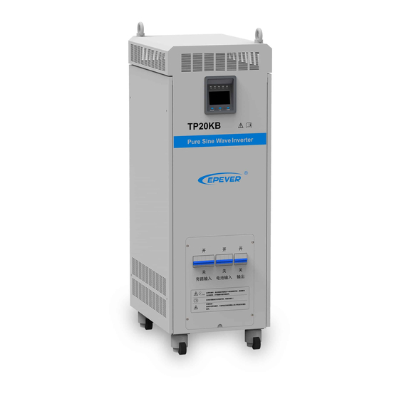
1.2 Structure ❶ Ring 2 pieces Carry the inverter. Include LED indicators, LCD, and buttons to indicate ❷ Display unit and display system operation state and parameters. See Chapter 3. ❸ Junction box cover plate To cover the terminals and circuit breakers. ⑴... - Page 9 (1) FOOT MASTER caster(Optional accessory) Rotate clockwise to raise the supporting feet, then to move the inverter. Rotate counterclockwise to lower the supporting feet, then to fix the inverter. (2) Terminals and breakers ❶ Bypass input arrester ❻ AC output terminals ❷...
-
Page 10: Name Definition
★ Interface connection method : (3) DC fan and AC fan DC fan (2 pieces): When the radiator temperature rises to 45℃ above, the DC fans will start; the DC fans will stop when the radiator temperature declines to 35℃ below. DC fans have the self-checking function when the inverter is powered on. -
Page 11: Connection Schematic Diagram
1.4 Connection schematic diagram The AC equipment must be determined according to the output power of the inverter. Do not connect the load exceeding the inverter's maximum input power. Otherwise, the WARNING inverter may be damaged. -
Page 12: Electrical Schematic Diagram
1.5 Electrical schematic diagram... -
Page 13: Installation
/3AWG AC/2P—63A TP20KB 35mm /1AWG AC/2P—100A TP30KB 42mm /1AWG AC/2P—150A TP40KB 50mm /1/0AWG AC/2P—200A Wire and circuit breaker selection for battery Model Battery wire size Breaker 35mm /1AWG(110VDC) DC/2P—125A TP10K TP10KB 25mm /3AWG(220VDC) DC/2P—63A TP20K 35mm /1AWG DC/2P—125A TP20KB... -
Page 14: Instructions
TP30K 42mm /1AWG DC/2P—200A TP30KB TP40K 50mm /1/0AWG DC/2P—250A TP40KB Wire and circuit breaker selection for AC output Model AC wire size Breaker TP10K 25mm /3AWG AC/2P—63A TP10KB TP20K 35mm /1AWG AC/2P—100A TP20KB TP30K 42mm /1AWG AC/2P—150A TP30KB TP40K... - Page 15 Step3: Takedown the junction box cover plate with special tools. Step4: Wiring...
- Page 16 Mobile APP For Android only) Download software: www.epever.com--EPEVER (TP) Communication cable: M12-6-male pin + crystal head-1000mm-v1.0 Modules: EPEVER WiFi 2.4G RJ45 A and EPEVER BLE RJ45 A PC Software Download software: www.epever.com--Inverter Monitor (TP) Communication cable: 1. M12-6-male pin + crystal head-1000mm-v1.0 2.
- Page 17 The indicator: Utility indicator on solid Step9: Close the load circuit breaker Step10: Inverter output Method 1: Press the "AC output" button for 3 seconds, the inverter would start the output. Method 2: Connect the remote switch, short-circuit cable 1(red), cable 2(white) of the remote switch, and RS485 communication interface;...
-
Page 18: Output Voltage/Frequency Grade Switch
If the power is supplied to the different AC loads, it is suggested to turn on the loads with a larger surge current till the load works well, then turn on the loads with a smaller surge current. Especially for inductive loads, they should be turned on one by one. -
Page 19: Interface
3 Interface 3.1 Indicator Indicator Color Status Instruction No utility input On Solid Utility input but no load Utility Green Slowly Flashing(0.5Hz) Utility bypass with load Fast Flashing(2.5Hz) Utility fault Inverter OFF On Solid Inverter Priority Inverter Green Slowly Flashing(0.5Hz) Inverter working Fast Flashing(2.5Hz) Inverter fault... -
Page 20: Buzzer
3.2 Buzzer Buzzer Instruction No beep No operation and fault One beep Operation succeed Buzzer beep every10s Fault prompt Buzzer beep every1s Fault warning 3.3 Buttons Button Operation Instruction Press the button Return the voltage interface quickly Inverter/Bypass Press the button and hold on 3s Switch the inverter and bypass mode Browse the Utility/Battery/Load column Press the button... -
Page 21: Icon
❶ ❻ Utility Fault code ❷ Battery ❼ AggConsum Utility parameters ❸ ❽ Load status Voltage/Current/Power/Frequency Battery parameters ❹ ❾ System running in bypass status Voltage/Current/Power Load parameters ❺ ❿ System running in inverter status Voltage/Current/Power/Frequency 3.5 Icon Icon Instruction Icon Instruction Load≤25%... - Page 22 2) Switch from inverter mode to bypass mode Operation: Press the "inverter/bypass" button for 3seconds; bypass indicator changes from off to solid on, inverter indicator changes to off status. 3) Clear electricity mode Operation: Press the "inverter/bypass" and "browse" buttons for 3seconds together to clear the accumulated consumed electricity.
-
Page 23: Protection
4 Protection Protection Phenomenon Protection Recovery Input reverse When DC input reverses polarity, the polarity The equipment would not be damaged. Resume work normally after correction. LCD would be off. protection Inverter mode: The Inverter stops working and switches DC input voltage exceeds the max. When the input voltage backs to normal, to the bypass mode. - Page 24 Buzzer sounds in short cycle The output power is 1.1 times greater than the rated power Output overload AC output stops Reduce the load power. Fault code "OOL" Buzzer sounds in short cycle Recover the output after the load short circuit failure is cleared Shut off the output immediately, auto recover the output three times (The first...
- Page 25 Inverter mode: Bypass input voltage lower than The inverter works normally, AC output When the bypass input voltage backs to 176VAC continues. normal, the fault warning stops. Fault code "BLV" Buzzer sounds in long cycle Bypass low voltage Bypass mode: Bypass input voltage...
-
Page 26: Troubleshooting
5 Troubleshooting DC input troubleshooting Fault Working Fault LED indicators Buzzer Status Troubleshooting Code mode — — — — Input reverse polarity LCD screen off Correct the wire connection of DC input polarity. Inverter Check whether the DC input voltage exceeds Inverter indicator fast mode the max. - Page 27 Inverter Check whether the bypass input voltage is lower mode Bypass low voltage than 176VAC. Recover when the voltage rises to Bypass 220VAC. mode Inverter mode Bypass frequency Check whether the bypass input frequency is in abnormal the range of 50Hz/60Hz± 10%. Bypass mode ...
-
Page 28: Maintenance
6 Maintenance The following inspections and maintenance tasks are recommended at least two times per year for the best performance. Make sure no block on airflow around the inverter. Clear up any dirt and fragments on the radiator. Check all the naked wires to ensure insulation is not damaged for serious solarization—frictional wear, dryness, insects or rats, etc. -
Page 29: Specifications
7 Specifications Item TP10K-110/220-1 TP10KB-110/220-1 TP10K-220/220-1 TP10KB-220/220-1 Technical parameters Rated input voltage 110VDC 220VDC Battery Input voltage range 93VDC ~ 146VDC 187VDC ~ 293VDC Max. input current 122A Rated output power 10000VA Output voltage 220/230VAC± 3% (Battery power mode) Output frequency 50Hz/60Hz±... - Page 30 Item TP20K-220/220-1 TP20KB-220/220-1 TP30K-220/220-1 TP30KB-220/220-1 Technical parameters Rated input voltage 220VDC Battery Input voltage range 185VDC ~ 295VDC 185VDC ~ 295VDC Max. input current 150A 234A Rated output power 20000VA 30000VA Output voltage 220/230VAC± 3%(Battery power mode) Output frequency 50Hz/60Hz± 3%(Battery power mode) 50Hz/60Hz±...
- Page 31 Enclosure IP20 Relative humidity range 0 ~ 95%(N.C.) Altitude 5000m (Derating above1500m)★ ★ Instruction for inverter derating 1. Temperature derating for TP10K,TP10KB,TP20K,TP20KB,TP30K,TP30KB: For each increase of 1℃ above 45℃, the output power is reduced by 5% of the rated power.
- Page 32 TP10K, TP10KB TP20K, TP20KB TP30K, TP30KB 2. Temperature derating for TP40K, TP40KB: For each increase of 1℃ above 30℃, the output power is reduced by 750W.
- Page 33 3. Altitude derating: For each increase of 500m above 1500m, the output power is reduced by 5% of the rated power. TP10K, TP10KB TP20K, TP20KB...
- Page 34 TP30K, TP30KB TP40K, TP40KB...
-
Page 35: Annex 1 Disclaimer
Annex 1 Disclaimer This warranty does not apply under the following conditions: Damage from improper use or use in an unsuitable environment. Load or utility current, voltage, or power exceeds the rated value of the inverter. Damage caused by the ambient temperature exceeds the limit working environment temperature. ... -
Page 36: Annex 2 Mechanical Dimension Diagram
Annex 2 Mechanical Dimension Diagram 1.TP10K, TP10KB... - Page 37 2. TP20K, TP20KB...
- Page 38 3. TP30K, TP30KB...
- Page 39 4. TP40K, TP40KB Any changes without prior notice! Version number: V2.1...
- Page 40 HUIZHOU EPEVER TECHNOLOGY CO., LTD. Beijing Tel: +86-10-82894896/82894112 Huizhou Tel: +86-752-3889706 E-mail: info@epever.com Website: www.epever.com...
Need help?
Do you have a question about the TP10K and is the answer not in the manual?
Questions and answers