
Related Manuals for Epever UC3522-1250P20C


Summary of Contents for Epever UC3522-1250P20C
- Page 1 Inverter/charger User Manual UC3522-1250P20C, UCP3522-1250P20C UC3542-0650P20C, UCP3542-0650P20C UC5542-1050P20C, UCP5542-1050P20C UC6042-1250P20C...
-
Page 3: Table Of Contents
Contents Important Safety Instructions..............1 Disclaimers....................5 1 General Information.................6 1.1 Overview............................6 1.2 Appearance...........................9 1.3 Naming rules..........................12 1.4 Connection diagram......................... 13 2 Interface....................15 2.1 Indicator............................15 2.2 Buttons............................16 2.3 Home screen..........................16 2.4 Real-time data..........................20 2.4.1 PV real-time data......................20 2.4.2 Utility real-time data...................... - Page 4 3.2 Wire and breaker size.......................63 3.3 Mounting the inverter/charger....................65 3.4 Wiring the inverter/charger.....................66 3.5 Operate the inverter/charger....................76 4 Working modes..................77 4.1 Abbreviation..........................77 4.2 Off-Grid working modes......................78 4.2.1 Battery mode........................78 4.2.2 No battery mode.......................84 4.3 On-Grid working modes......................85 4.3.1 On-Grid operation procedure..................85 4.3.2 Battery mode........................
- Page 5 8 Maintenance..................109 9 Specifications..................110 9.1 UC-P20C Series........................110 9.2 UCP-P20C Series........................115 10 Appendix....................119 10.1 Appendix1 Abbreviations index..................119 10.2 Appendix 2 Battery state instruction................122...
-
Page 6: Important Safety Instructions
Important Safety Instructions Please reserve this manual for future review. This manual contains all the safety, installation, and operation instructions for the UC/UCP-P20C series inverter/charger ("inverter/charger" referred to as this manual). 1. Explanation of symbols To enable users to use the product efficiently and ensure personal and property safety, please read the related words carefully when you encounter the following symbols in the manual. - Page 7 4. Safety cautions before installation When receiving the inverter/charger, please check if there is any damage in transportation. If you find any problem, please contact the transportation company or CAUTION our company in time. When installing or moving the inverter/charger, follow the instructions in the manual.
- Page 8 7. Safety cautions for inverter/charger operation When the inverter/charger works, the shell will generate much heat, and the WARNING temperature is very high. Please do not touch it, and keep it far from the equipment susceptible to high temperature. SURFACE ...
- Page 9 Improper maintenance of the inverter/charger may cause personal injury or equipment damage; It is recommended to wear an antistatic wrist strap or avoid unnecessary contact with the circuit board. The safety mark, warning label, and nameplate on the inverter/charger should be visible, not removed or covered.
-
Page 10: Disclaimers
Disclaimers The warranty does not apply to the following conditions: Damage caused by improper use or inappropriate environment (it is forbidden to install the inverter/charger in humid, salt spray, corrosion, greasy, flammable, explosive, dust accumulative, or other severe environments). The actual current/voltage/power exceeds the limit value of the inverter/charger. -
Page 11: General Information
1 General Information 1.1 Overview UC/UCP-P20C series, upgraded hybrid inverter/chargers that support utility charging, oil generator charging, solar charging, utility output, inverter output, and energy management. Equipped with main AC output and second AC output. After enabling the low-power mode on the LCD, the inverter/charger can enter the low-power mode according to the battery voltage and output power. - Page 12 where the electricity is unstable. Features Full intelligent digital energy storage equipment. Applicable for pure off grid/ backup power/ self-generation and self-consumption/ on grid situation. Support battery mode or non-battery mode. Non-battery mode: simultaneously charging with solar (Main) and Utility (Assist). ...
- Page 13 Lithium battery communication port to perform the safe charging and discharging. Comprehensive electronic protection. Anti-reverse connection protection for the battery input and PV input -20℃ to +50℃ operating temperature range to meets more environment requirements. IP20 enclosure design with Anti-Dust Kit (Dust removal is required regularly, and the specific requirements are detailed in chapter 8 Maintenance).
-
Page 14: Appearance
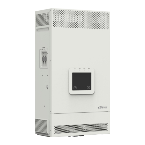
1.2 Appearance UC3522-1250P20C/UCP3522-1250P20C/UC3542-0650P20C/UCP3542-0650P20C/ UC6042-1250P20C... - Page 15 UC5542-1050P20C/UCP5542-1050P20C ...
- Page 16 RS485-A RS485-B RS485-B Please go to EPEVER official website to check or download the currently supported BMS manufacturers and the BMS parameters. (2) Dry contact specification: 1A@125VAC. Function: The dry contact interface is connected with the generator switch to turn on/off the generator.
-
Page 17: Naming Rules
Definition Definition HFS-BUS CAN-L PFS-BUS CAN-H PS-GND 6/7/8/9 Reserved 1.3 Naming rules Naming rules for UC-P20C series Naming rules for UCP -P20C series ... -
Page 18: Connection Diagram
1.4 Connection diagram No battery mode ... - Page 19 Battery mode AC loads shall be determined according to the output power of the inverter/charger. WARNING The load exceeding the maximum output power may damage the inverter/charger. For different battery types, confirm the relevant parameters before power on. ...
-
Page 20: Interface
2 Interface Note: The display screen can be viewed clearly when the angle between the end-user's horizontal sight and the display screen is within 90°. If the angle exceeds 90°, the information on the display screen cannot be viewed clearly. 2.1 Indicator Indicator Status... -
Page 21: Buttons
Green flashing (0.5Hz) Normal communication Red ON Communication fault 2.2 Buttons Buttons Operation Instruction Click Exit the current interface and return to home screen. Turn ON/OFF the load switch. Short press this button to pop up the following prompt message. Click ON/OFF to turn on/off the load switch. If set to "OFF", it will automatically return to "ON"... - Page 22 Instruction ❶ Display the system time. Please set the system time correctly before use. Displays the battery discharge mode. For specific parameter settings, see 2.5.1 Parameter list > 5. System (System parameter ❷ setting). PV > BP > BT PV > BT > BP BP >...
- Page 23 Click the PV icon to enter the PV real-time data screen, see 2.4.1 PV real-time data for details. Display utility input voltage and utility input current. The direction of the arrow shows the energy flow state of the utility input.
- Page 24 Display the output voltage and output current of the load. The arrow direction indicates the energy flow state of the load. The arc represents the percentage of the current load power to the rated load power. Display the load status: indicates that the load is on, ...
-
Page 25: Real-Time Data
Indicates that a fault has occurred in the current system. Click this icon to view real-time fault. For specific operations, see 2.4.6 Real-time error code. indicates turning on the built-in WIFI module. ⓬ indicates turning power supply inverter/charger’s COM port, which can be connected to an external Bluetooth or WIFI module. -
Page 26: Utility Real-Time Data
Icon Instruction 1. PV input voltage, PV input current 2. PV energy flow indication 3. PV real-time power Note: If there is only one PV input, only one PV icon will be displayed here. 1. Total PV generation (not displayed if there is only one PV input) 2. -
Page 27: Inverter/Charger Real-Time Data
Icon Instruction 1. Utility input voltage, current, frequency 2. Utility energy flow instructions 3. Energy feed into the grid (the arrow points to the grid); utility consumption power (the arrow points to the inverter/charger.) Swipe up and down in this area to see all the settings of the utility. Refer to "2.5.1 Parameter list >... -
Page 28: Load Real-Time Data
2.4.4 Load real-time data On the home screen, touch to enter the load real-time data screen. Click Fun to display the Payload Real-time Data, Setting Parameters To Display page, and Parallel Real-Time Data page. Click Page to display all the information for the current page. 2.4.5 Battery real-time data On the home screen, touch to enter the battery real-time data screen. - Page 29 Icon Instruction 1. Click to display Other Setting, BMS Data, Voltage Setting, and SOC Setting. 2.Click NEXT Page to shows all the information for the current page. To display the SOC value of the battery, click this icon to display the following BMS State screen, see Battery state instruction in Appendix 2 for details.
-
Page 30: Real-Time Error Code
2.4.6 Real-time error code If there is no fault in the current system, will be displayed on the home screen. If there is a fault in the current system, will be displayed on the home screen. Touch this icon to enter the real-time error code screen. - Page 31 2. Enter the password input screen, enter the 1. On the home screen, click in the correct password (the initial password is 000000 upper-right corner. by default), and click to enter the parameter setting screen. The parameter setting screen includes: PV (PV parameter setting), Charge (battery charge control parameter setting), Grid (Grid parameter setting), Load (Load parameter setting), System (System parameter setting), Others (Other parameters setting) and password setting.
- Page 32 1. PV (PV parameter setting) On the parameter setting screen, click PV to enter the PV parameter setting screen. The following information is displayed: Icon Instruction Default values and settable ranges of PV parameters. Swipe up and down to view all the parameters on the current page. indicates that the parameter value can be customized (If the parameter is read-only, there is no icon).
- Page 33 Protection Temperature) Read-only. PV Over Temperature Protection Temperature 70.0℃ for UC3522-1250P20C/UCP3522-1250P20C/ UC3542-0650P20C/UCP3542-0650P20C. Read-only. PV Over Temperature Protection Reconnect 70.0℃ Temperature for UC5542-1050P20C/ OTPR (Over UCP5542-1050P20C/UC6042-1250P20C. Temperature Protection Read-only. PV Over Temperature Protection Reconnect Reconnect Temperature) Temperature for UC3522-1250P20C/ 65.0℃ UCP3522-1250P20C/UC3542-0650P20C/ UCP3542-0650P20C.
- Page 34 2. Charge (Battery charge control parameter setting) On the parameter setting screen, click Charge to enter the battery charge control parameter setting screen. The following information is displayed: Icon Instruction Default values and settable ranges for battery voltage/SOC control parameters. Swipe up and down to view all the parameters on the current page.
- Page 35 Parameter Default User define 60.0V User define: (Discharging Limit Voltage plus 0.15*N) ≤ OVR (Over Voltage (48V system) Over Voltage Reconnect Voltage ≤ (Over Voltage Reconnect Voltage) Disconnect Voltage minus 0.1*N), step size: 0.1V. Note: 30.0V (24V system) N=Rated battery voltage/12. 58.4V User define: Boost Charging Voltage ≤...
- Page 36 Parameter Default User define User define: (Discharging Limit Voltage plus 0.1*N) ≤ Under Voltage Warning Voltage ≤ (Under Voltage 48.0V Warning Reconnect Voltage minus 0.1*N), step size: (48V system) 0.1V UVW (Under Voltage Note: N=Rated battery voltage/12. This voltage is also Warning Voltage) the disconnect voltage for the AC output main 24.0V...
- Page 37 Parameter Default User define 2.2 SOC Control Strategy It takes effect after the “BCCMode” is set as “SOC.” When the battery SOC is higher than or equals to this value, the inverter/charger will stop charging the FCP (Full Charging battery. 100% Protection SOC) User define: (Full Charging Protection Reconnect SOC...
- Page 38 Parameter Default User define It takes effect after the “BCCMode” is set as “SOC.” User define: 20% to 50%, or 20% to (Utility Charging UAC ON (Utility OFF SOC minus 10%), step size: 1% Charging ON SOC) Note: Take the minimum value between 50% and (Utility Charging OFF SOC minus 10%).
- Page 39 Default value and setting range for Grid parameters as shown in the below: Parameter Default User define 3.1 Grid Setting Parameter UOD (Utility Over Voltage User define: (Utility Over Voltage Reconnect Voltage 265.0V Disconnect Voltage) plus 10V) to 285.0V, step size: 0.1V UOR (Utility Over Voltage User define: 220.0V to (Utility Over Voltage Disconnect 255.0V...
- Page 40 (Enter into the “Load Setting Parameter” screen again to check if the change has been changed). Read-only. Load Current Limit for 35.0A UC3522-1250P20C/UCP3522-1250P20C/ UC3542-0650P20C/UCP3542-0650P20C. Load CL (Load Current Limit) Read-only. Load Current Limit for 42.0A UC5542-1050P20C/UCP5542-1050P20CC/ UC6042-1250P20C.
- Page 41 Read-only. Temperature Upper Limit for 75.0℃ UC5542-1050P20C/UCP5542-1050P20C/ UC6042-1250P20C. TempUL (Temperature Upper Limit) Read-only. Temperature Upper Limit for 70.0℃ UC3522-1250P20C/UCP3522-1250P20C/UC3542-0 650P20C/ UCP3542-0650P20C. Read-only. Temperature Upper Limit Recovery for 70.0℃ UC5542-1050P20C/UCP5542-1050P20C/ TempULR (Temperature UC6042-1250P20C. Upper Limit Recovery) Read-only. Temperature Upper Limit Recovery for 65.0℃...
- Page 42 LBACC (Local Battery 100.0A UCP5542-1050P20C, step size: 0.1A. Namely, the Available Charging maximum allowable charge current on battery side. Current) User define: 5.0A to 120.0A for UC3522-1250P20C/ UCP3522-1250P20C/UC6042-1250P20C, step 120.0A size: 0.1A. Namely, the maximum allowable charge current on battery side.
- Page 43 UC6042-1250P20C, step size: 0.1A. Namely, the Available Discharging maximum allowable discharge current on battery Current) side. User define: 10.0A to 380.0A for UC3522-1250P20C/ UCP3522-1250P20C, step 380.0A size: 0.1A Namely, the maximum allowable discharge current on battery side. BECT (Battery Equalize...
- Page 44 Parameter Default User define BATT OTPR (Battery Over User define: 30.0 ℃ to (Battery Over Temperature 45.0 ℃ Temperature Protection Protection minus 5 ℃ ), step size: 0.1 ℃ Recovery) Chrg (Charging) Enable Read-only Dischrg (Discharging) Enable Read-only User define: Disable, Enable Note: The parameter will only take effect when used PCUP (Phase Current in three phase.
- Page 45 User define: 0.1KW to 5.5KW for 3.4KW UC5542-1050P20C/ UCP5542-1050P20C, step size: 0.1KW User define: 0.1KW to 3.5KW for GridULP (Grid Upper Limit UC3522-1250P20C/ UCP3522-1250P20C/ Power) 2.3KW UC3542-0650P20C/UCP3542-0650P20C, step size: 0.1KW User define: 0.1KW 6.0KW...
- Page 46 Otherwise, the “BADC” value equals the setting Read-only, the maximum allowable discharge value of “LBADC” after 380.0A current on battery side for UC3522-1250P20C/ each power-on. If UCP3522-1250P20C. “LBADC” is changed without a subsequent restart, the “BADC” value remains the previous...
- Page 47 100.0A Charging Current) size: 0.1A. Namely, the maximum current at the battery end when the utility charges the battery. User define: 5.0A to 110.0A for UC3522-1250P20C/ UCP3522-1250P20C, step size: 0.1A 110.0A Namely, the maximum current at the battery end when the utility charges the battery.
- Page 48 Parameter Default User define User define: VOL (Voltage), SOC VOL: The battery voltage control parameters take effect after setting this value as “VOL.” BCCMode (Battery SOC: The SOC parameters take effect after setting Charging Control Mode) this value as “SOC.” Note: If "SOC"...
- Page 49 Parameter Default User define 5.4 System Time Setting 5.5 Local Parameters User define: 50% to 100% LCD BRT (LCD 100% It indicates the LCD brightness when operating the Brightness) LCD. User define: 6S to 60S, step size: 1S TODelay (Idle Timeout After not operating the LCD, when the set 15 S Delay)
- Page 50 Parameter Default User define User define: ON, OFF When set to "OFF," the LED indicator is off User define: 1 second to 3600 seconds, step size: 1 second Set the time interval for recording the historical data (History Record (only refers to the voltage, current and other data Interval) stored regularly, excluding the historical faults.
- Page 51 Parameter Default User define User define: ON, OFF Screen TO (Screen LCD backlight switch. Set to "ON," the LCD backlight will Timeout) turn off after the "TODelay" time plus the "SOT" time has elapsed. Set to "OFF," the LCD backlight will remain on. User define: Normal Mode, Standby Mode To reset the settings parameters: select "Standby Mode,"...
- Page 52 Parameter Default User define User define: Day Month Year, Total Generation Clear Statistical Day Month After selecting "Day Month Year" or "Total Generation", Power Year press the "Clear" button to clear the corresponding cumulative energy. 7. Set password 1. On the parameter setting page, click Set 2.
- Page 53 8. Quick Setting Of BMS Parameters Note:Enter the “Quick Setting Of BMS Parameters” screen without an administrator password, allowing for rapid configuration of BMS related parameters. 1. On the home screen, click in the 2. Enter the password input screen, click upper-right corner.
- Page 54 3. Select the “Battery Type” and “Protocol Number” according the actual situation, and click to back to the home screen. After select the “Protocol Number,” the default settings corresponding to the BMS protocol will be automatically loaded. The “BMS Enable” is in the “Enable” state by default and display ( in this state, the “BCCMode”...
-
Page 55: Battery Work Modes
2.5.2 Battery work modes The following table lists the recommended working mode and setting process for different application scenarios. According to your current battery status (such as whether it is a lithium-ion battery pack, whether it has BMS function, whether it has current control function at the end of charge and discharge, etc.), you can reasonably set the parameters to ensure that the battery works in the optimal performance, so as to ensure the safe operation of the system for a long time. - Page 56 2. Enter the password input screen, enter the 1. On the home screen, click in the correct password (the initial password is 000000 upper-right corner. by default), and click enter the parameter setting screen. 3. Slide up and down on the current screen, 4.
- Page 57 5. Click to switch to the "Charge and Discharge Management" screen, and set "BCCMode (Battery Charging Control Mode)" to "VOL" or "SOC." After the settings are complete, click to issue new parameter value. Figure 2 “Setting process for lithium battery pack with BMS and current control function” ...
- Page 58 BMSVolt (BMS Voltage Control), BMSCurr (BMS Current Control)." After the settings are complete, click to issue new parameters. Please go to EPEVER official website to download the currently supported BMS manufacturers and the BMS parameters. The inverter/charger will control charging and discharging based on the LCD ...
- Page 59 consistency of lithium batteries from different manufacturers, it is necessary for professionals to guide the use of charging and discharging. Figure 3 “Setting process for lithium battery pack with BMS, without current control function” When the system adopts a lithium battery pack with BMS, while without current control function at the end of charge and discharge, and the lithium battery pack can communicate with the inverter/charger normally, follow the flowchart below to set parameters correctly.
- Page 60 3. Slide up and down on the current screen, 4. Depending on the battery actually used, set and click System to enter the system parameter "BDCap(Battery Design Capacity) and BType setting screen. (Battery Type)." After the settings are complete, click to issue new parameter value.
- Page 61 flowchart below to set parameters correctly. The inverter/charger controls charging and discharging based on the LCD settings. Parameter Set value BDCap Battery Basic Properties Set it according to the battery you are (Battery Design Capacity) actually using. BType (Battery Type) To set as “VOLT”...
-
Page 62: Battery Voltage Control Parameters
setting screen. (Battery Type)." After the settings are complete, click to issue new parameter value. 5. Click to switch to the "Charge and Discharge Management" screen and set "BCCMode (Battery Charging Control Mode)." After the settings are complete, click to issue new parameters. - Page 63 When the battery voltage is lower than 21.6V, the battery inverter output must be derated. Curve of Continuous output power Vs battery voltage for UC3522-1250P20C/UCP3522-1250P20C as below: The parameters are measured in the condition of 48V/25 ºC. Battery Type OPZS...
- Page 64 The following rules must be obeyed when setting the Lead-acid battery voltage control parameters. A. Over Voltage Disconnect Voltage > Charging Limit Voltage ≥ Equalize Charging Voltage ≥ Boost Charging Voltage ≥ Float Charging Voltage > Boost Voltage Reconnect Voltage B....
- Page 65 Voltage E. Boost Voltage Reconnect Voltage > Low Voltage Reconnect Voltage 2) Lithium battery voltage control Battery Type 24V system 48V system User User LFP8S LFP15S LFP16S Voltage control parameters Define Define Over Voltage Disconnect Voltage 29.6V 21.5–32V 55.5V 59.2V 42.8–64V Charging Limit Voltage 29.2V...
- Page 66 42.8 21.5– Under Voltage Warning Voltage 21.0V 24.5V 45.5V 49.0V –64V 42.8 21.5– Low Voltage Disconnect Voltage 19.2V 22.4V 41.6V 44.8V –64V Discharging Limit Voltage 18.6V 21.7V 40.3V 43.4V value value When setting the Lithium battery voltage control parameters, the following rules must be obeyed. Over Voltage Disconnect Voltage <...
-
Page 67: Single Installation
3 Single Installation 3.1 Attention Please read the manual carefully to familiarize yourself with the installation steps. Be very careful when installing the batteries, especially flooded lead-acid batteries. Please wear eye protection, and have fresh water available to rinse if contact with battery acid. ... -
Page 68: Wire And Breaker Size
PV module's Isc. The PV array's Isc must not exceed the maximum PV input current. For max. PV input current and max. PV wire size, please refer to the table below: Model PV wire size Circuit breaker UC3522-1250P20C /11AWG 2P—20A (with arc extinguishing function) UC3542-0650P20C UCP3522-1250P20C /10AWG 2P—25A (with arc extinguishing function) - Page 69 When the PV modules are connected in series, the total voltage must not exceed the max. PV open circuit voltage 500V (At minimum operating environment temperature), CAUTION or 440V (At 25℃). Recommended Utility wire size Model Utility wire size Circuit breaker UC3522-1250P20C UC3542-0650P20C /10AWG 2P—32A UCP3522-1250P20C UCP3542-0650P20C UC5542-1050P20C UC6042-1250P20C 10mm /7AWG 2P—50A...
-
Page 70: Mounting The Inverter/Charger
The wire size is only for reference. Suppose a long distance exists between the PV array, the inverter/charger, and the battery. In that case, larger wires shall be used to reduce the voltage drop and improve the system's performance. CAUTION ... -
Page 71: Wiring The Inverter/Charger
Connect the inverter/charger in the order of “❶Ground > ❷Battery > ❸Load > ❹PV ❺Utility or Generator > ❻Optional accessories”, and disconnect the inverter/charger in the reverse > following wiring sequence illustrated appearance order. "UC3522-1250P20C/UCP3522-1250P20C/UC3542-0650P20C/UCP3542-0650P20C/ UC6042-1250P20C." For wiring positions of other models, please refer to the actual product appearance. - Page 72 No battery mode ...
- Page 73 Battery mode Grounding The inverter/charger has a dedicated grounding terminal, which must be grounded reliably. The grounding wire size must be consistent with the recommended load wire size. The grounding connection point shall be as close as possible to the inverter/charger, and the total grounding wire shall be as short as possible.
- Page 74 Do not ground the battery terminals. Do not ground the PV terminals. Do not ground the AC input L or N terminals between the inverter/charger No grounding and the household power distribution cabinet. Do not ground the AC output L or N terminals. ...
- Page 75 Connect the AC load Risk of electric shock! When wiring the AC load, please disconnect the circuit breaker and ensure that the poles' leads are connected correctly. The AC loads shall be determined by the continuous output power of the inverter/charger.
- Page 76 Control logic for main and second power off of AC output When the battery voltage is lower than the UVW (Under Voltage Warning Voltage), the AC output main power-off relay will be disconnected after a 5-second delay. Once the battery voltage rises above the LVR (Low Voltage Reconnect Voltage), the AC output main power-off relay will be reconnected after a 5-minute delay, restoring the output of the AC output main load interface.
- Page 77 AC OUTPUT (MAIN) connection AC OUTPUT (SECOND) connection ...
- Page 78 Connect the PV modules Risk of electric shock! The PV array can generate dangerous high-voltage! Disconnect the circuit breaker before wiring, and ensure that the leads of "+" and "-" poles are connected correctly. WARNING It is forbidden to connect the positive and negative poles of the PV with the ground; otherwise, the inverter/charger will be damaged.
- Page 79 After the Utility is connected, the PV and battery cannot be grounded. In contrast, the inverter/charger cover must be grounded reliably (to shield the outside electromagnetic interference effectively and prevent the cover from causing electric shock to the human body). There are various types of oil generators with complex output conditions.
- Page 80 Working principle: When the battery voltage reaches the DCT ON (Dry Contact ON Voltage) the dry contact is connected. Its coil is energized. The dry contact can drive loads of no more than 125VAC /1A, 30VDC/1A. According to different battery types of the inverter charger, the default values of the DCT ON (Dry Contact ON Voltage) and the DCT OFF (Dry Contact OFF Voltage)are different.
-
Page 81: Operate The Inverter/Charger
3.5 Operate the inverter/charger Step 1: Double-check whether the wire connection is correct. Step 2: Connect the battery circuit breaker. Step 3: Turn on the power switch. The LCD will be lit, which means the system running is normal. Power switch ... -
Page 82: Working Modes
4 Working modes 4.1 Abbreviation Abbreviation Instruction PV power Load power LOAD Battery voltage Low Voltage Disconnect Voltage Low Voltage Reconnect Voltage Low Energy Disconnect SOC Low Energy Disconnect Recover SOC AUX OFF Auxiliary module OFF voltage (namely, Utility charging OFF voltage) AUX ON Auxiliary module ON voltage (namely, Utility charging ON voltage) UAC OFF... -
Page 83: Off-Grid Working Modes
4.2 Off-Grid working modes 4.2.1 Battery mode Scenario A: Both PV and Utility are not available. Regardless of the input and output sources, the working mode is as follows. ❶Any of the following is satisfied, the battery supplies the load. ... - Page 84 ❷ When the PV power is lower than or equal to the load power, the PV will not charge the battery, the battery will cut in to supply power to the load together with the PV. ≥ LVR ≤ LVD / SOC ≥...
- Page 85 ❸ Any of the following is satisfied, the Utility supplies power to the load, and the PV prioritizes charging the battery. The battery voltage is lower than or equal to the LVD value. The battery SOC is lower than or equal to the DP value.
- Page 86 ❸ Any of the following is satisfied, the Utility supplies power to the load and charges the battery together with the PV. The battery voltage is lower than or equal to the AUX ON value. The battery SOC is lower than or equal to the UAC ON value.
- Page 87 Discharging Mode: No impact under any Charging Mode: "Solar+Grid" ❶ When the PV power is greater than the mode (LBACC*V ), the Utility and PV supply power to the load, and the PV charges the battery simultaneously. (C-5) > LBACC*V ≤...
- Page 88 Discharging Mode: "PV>BP>BT" Charging Mode: "Solar" "BP>PV>BT" (D-2) The Utility supplies power to the load. Utility Charging Mode: "Solar > (D-3) Discharging Mode: "PV>BT>BP" ❶Any of the following is satisfied, the battery Grid" Utility supplies the load. ...
-
Page 89: No Battery Mode
❷Any of the following is satisfied, the Utility supplies power to the load and charges the battery simultaneously. The battery voltage is lower than or equal to the AUX ON value. The battery SOC is lower than or equal to the UAC ON value. -
Page 90: On-Grid Working Modes
❷When the PV power is lower than or equal to the load power, the PV and the Utility supply power to the load together. Only the PV supplies power to the load. Utility Only the Utility supplies power to the load. ... -
Page 91: Battery Mode
4. Click to switch to the "Advanced 3. Slide up and down on the current screen, Battery Properties" screen, set "Grid" to and click System to enter the system parameter "Enable", and set "GridULP.” After the settings setting screen. are completed, click to issue new parameter values. - Page 92 ❸ When the PV power is lower than or equal to (LBACC*V ), the Utility supplies power to the load, and the PV charges the battery. ≤ AUX ON ≥ AUX OFF / SOC ≤ UAC ON / SOC ≥ UAC OFF ❹...
-
Page 93: No Battery Mode
❷ When the PV input power is lower than or equal to the sum of the charging power and the load power, while it is greater than the (LBACC*V ), the PV charges the battery first, and supplies power to the load together with the Utility. -
Page 94: Operation For Built-In Wifi Module
5 Operation for built-in WiFi module 5.1 Turn on the built-in WiFi module 2. Enter the password input screen, enter the 1. On the home screen, click in the correct password (the initial password is 000000 upper-right corner. by default), and click enter the parameter setting screen. - Page 95 set parameters by PC or APP (the following takes APP as an example) 1. Download APP iOS QR code ( or search for "Solar Android QR code Guardian" in the Apple Store) 2. Register & Login Download the APP and open it, click the “Sign up now” ❶...
- Page 96 and connect to the local WiFi network (a 2.4G gateways and devices to the site with one click. WiFi network is a must). Step 3: Enter the "Gateway and Device Addition" interface.
- Page 97 (1) Gateway name: The APP generates a default name, which the user can modify to any desired name. ① (2) Access method: Select EPEVER WiFi 2.4G RJ45 D. (3) Gateway SN: Get the 22-character SN by scanning the QR code on the inverter/charger’s label or manually entering it.
- Page 98 Step 5: Click "WiFi Settings" to connect the Step 4: Enter the correct router WiFi name and mobile phone to the gateway’s WiFi hotspot corresponding password. Click "Next Step". (Name: HN_EPxxx, password: 12345678). After successful connection, back to the APP and click "Next Step."...
- Page 99 Step 8: After successful addition, enter the Step 9: Enter the device data interface to view device list automatically and click on any device real-time information, “Configuration icon. Overview” is displayed by default. 4. Add device (There is no local 2.4G WiFi network) Step 1: Open the APP and click the “Local Step 2: Enter the WiFi interface, click the Connection”...
- Page 100 Step 3: Enter the "Add Device" interface. 1. Fill in the relevant information of the device. (1) Device Custom Name: The APP generates a default name, which the user can modify to any desired name. (2) Select Products series: Select the correct product series according to the user's equipment, otherwise the equipment cannot communicate normally.
- Page 101 Step 4: Enter the device data interface to view real-time information...
-
Page 102: Protections
6 Protections Protections Instruction When the PV array's actual charging current/power exceeds its rated current/power, it will charge the battery as per the rated current/power. When the PV voltage exceeds the bus voltage, the PV input power is constrained PV limit Current/Power by the load power, charging power, the power that the solar panels can deliver, and the current of the PV circuit breaker. - Page 103 The inverter/charger will resume charging/discharging when the internal temperature is normal and the protection time lasts more than 20 minutes. 3605W≤P˂4550W 4550W≤P˂5250W 5250W≤P˂7000W P≥7000W UC3522-1250P20C UC3542-0650P20C Protect after 30 seconds Protect after 10 seconds Protect after 5 seconds Protect immediately...
- Page 104 Protections Instruction 3850W≤P˂4795W 4795W≤P˂5495W 5495W≤P˂7000W P≥7000W UC3522-1250P20C UC3542-0650P20C Protect after 30 seconds Protect after 10 seconds Protect after 5 seconds Protect immediately UCP3522-1250P20C UCP3542-0650P20C Note: The output is recovered automatically after a delay time of 5s, 10s, and 15s separately. The Utility bypass overload inverter/charger stops working after the 4th protection and can resume working after resetting or restarting.
- Page 105 Protections Instruction 8550W≤P˂9485W 9485W≤P˂10585W P≥10585W UC5542-1050P20C Protect after 30 seconds Protect after 10 seconds Protect immediately UCP5542-1050P20C Utility bypass overload Note: The output is recovered automatically after a delay time of 5s, 10s, and 15s separately. The (Battery mode) inverter/charger stops working after the 4th protection and can resume working after resetting or restarting. 6120W≤P˂6600W 6600W≤P˂7980W P≥7980W...
-
Page 106: Troubleshooting
7 Troubleshooting After the inverter/charger is powered on, the meter displays the boot screen all the time (unable to enter the home screen) and the red "RUN" indicator flashes. It means the communication with the inverter/charger is error. When the above fault occurs, check whether the CAUTION communication cable is disconnected. - Page 107 Error Fault/Status Indicator Buzzer Solution code Ensure the battery is installed in a cool and well-ventilated place, check that the battery actual charging and discharging current does not exceed Battery Over the setting values of "LBACC (Local Battery Available Charging Current) ER11 Temperature and LBADC (Local Battery Available Discharging Current)."...
-
Page 108: Pv Faults
7.2 PV faults Error Fault/Status Indicator Buzzer Solution code Check if the PV open-circuit voltage is higher than OVP (Over Voltage Intermitte PV1 Overvoltage ER15 indicator Protection Voltage). The alarm is released when the PV open-circuit nt beeps red on voltage is below OVPR (Over Voltage Protection Reconnect Voltage). -
Page 109: Inverter Faults
7.3 Inverter faults Error Fault/Status Indicator Buzzer Solution code Check if the load actual power exceeds the "Inverter Rated Power (see chapter 9 Specifications)," disconnect the load completely and turn off Inverter Output ER02 the inverter/charger. Wait 5 minutes and then turn on the Overcurrent inverter/charger to check if it resumes normal. - Page 110 Error Fault/Status Indicator Buzzer Solution code Disconnect the load completely and turn off the inverter/charger. Wait 5 Inverter Current OFFSET ER35 minutes and then turn on the inverter/charger to check if it resumes Error normal. If it is still abnormal, please contact our technical support. LOAD Turn off the inverter/charger.Wait 5 minutes and then turn on the Inverter Temp Sensor...
-
Page 111: Utility Faults
7.4 Utility faults Error Fault/Status Indicator Buzzer Solution code Check if the utility voltage is exceeds the UOD (Utility Over Voltage GRID Disconnect Voltage), then disconnect the AC input and turn off the Intermitte Utility Overvoltage ER08 indicator inverter/charger. Wait 5 minutes and then turn on the inverter/charger to nt beeps red on check if it resumes normal. -
Page 112: Load Faults
7.5 Load faults Fault/Status Error code Indicator Buzzer Solution Load Current ER33 Disconnect the load completely and turn off the inverter/charger. OFFSET Error Wait 5 minutes and then turn on the inverter/charger to check if it Load Over Load ER48 LOAD Intermitt resumes normal. -
Page 113: Bms Faults
Error Fault/Status Indicator Buzzer Solution code Turn off the inverter/charger. Wait 5 minutes and then turn on the Environment Temp ER42 inverter/charger to check if it resumes normal. If it is still abnormal, Sensor Disconnected please contact our technical support. Low Temperature ER46 Check whether the ambient temperature is lower than the set "LTSChrg... -
Page 114: Maintenance
8 Maintenance To prevent frequent over-heat protection of the inverter/charger, which may affect system reliability, it is recommended to clean the anti-dust kit once a month. In environments with high temperatures and severe dust pollution, it is advisable to clean the anti-dust kit every two weeks. -
Page 115: Specifications
9 Specifications 9.1 UC-P20C Series Model UC3542-0650P20C UC5542-1050P20C Utility input 176VAC to 264VAC (Default), 90VAC to 285VAC Utility Input Voltage (Configurable) Utility Input Frequency 45Hz to 65Hz Maximum Utility Charging 100A Current Switch Response Time – Inverter to Utility: 10ms Switch Response Time Switch Response Time –... - Page 116 590mm × 300mm × 163mm Height) Mounting size (Length x Width) 512mm × 245mm 568mm × 245mm Mounting hole size Φ9mm/Φ10mm Φ9mm/Φ10mm Net Weight 12.7Kg 15.5Kg Model UC3522-1250P20C Utility input 176VAC to 264VAC (Default), 90VAC to 285VAC Utility Input Voltage (Configurable)
- Page 117 Utility Input Frequency 45Hz to 65Hz Maximum Utility Charging 110A Current Switch Response Time – Inverter to Utility: 10ms Switch Response Time Switch Response Time – Utility to Inverter (when the load power is higher than 100W): 20ms Utility output Utility Output Voltage 176VAC to 264VAC Utility Output Frequency...
- Page 118 Battery Work Voltage Range 20.4VDC to 32.0VDC Battery Maximum Charging 120A Current Others No-load Losses ≤1.5A Test condition: Utility, PV and Load are disconnected, AC output is ON, fan stops, @24V input Standby Current ≤1.1A Test condition: Utility, PV and Load are disconnected, AC output is OFF, fan stops, @24V input Communication with BMS RS485...
- Page 119 Power Factor 0.99 Inverter output Inverter Rated Power (@30℃) 6000W 3-second Transient Surge Output 12000W Power Inverter Output Voltage 220/230VAC±3% Inverter Frequency 50/60Hz±0.2% Output Voltage Waveform Pure sine wave Load Power Factor 0.2–1(VA ≤ Rated output power) THDu (Total Harmonic Voltage ≤3% (24V resistive load) Distortion) Maximum Load Efficiency...
-
Page 120: Ucp-P20C Series
Communication with BMS RS485 Communication with Portal RS485 Parallel Function Yes, 12 units in standard, 16 units at most -20℃ to +50℃ (When the environment temperature exceeds Work Temperature Range 30℃, the actual output power is reduced appropriately) Storage Temperature Range -25℃... - Page 121 Output Voltage Waveform Pure sine wave Load Power Factor 0.2–1(VA ≤ Rated output power) THDu (Total Harmonic Voltage ≤3% (48V resistive load) Distortion) Maximum Load Efficiency Maximum Inverter Efficiency Maximum Main Load 3500W 5500W Maximum Second Load 3500W 5500W Main Output Cut-Off Voltage Equal to “UVW (Under Voltage Warning Voltage)”...
- Page 122 Relative Humidity < 95% (N.C.) <4000M (If the altitude exceeds 2000 meters, the actual output Altitude power is reduced appropriately) Certifications and Standards IEC 62109-1, IEC 62109-2, IEC 61683, IEC 62368 Mechanical parameters Dimension (Length x Width x 534mm × 300mm × 590mm ×...
- Page 123 Solar controller 500V (At minimum operating environment temperature) PV Maximum Open-circuit Voltage 440V (At 25℃) MPPT Voltage Range 85V to 450V Number of MPPTs PV Maximum Input Current One way, 20A/way PV Maximum Short-circuit Current One way, 22A/way PV Maximum Input Power 4200W PV Maximum Charging Current 120A...
-
Page 124: Appendix
10 Appendix 10.1 Appendix1 Abbreviations index Abbreviations Full name in English Over Voltage Protection Voltage OVPR Over Voltage Protection Reconnect Voltage Solar Setting Under Voltage Protection Voltage Parameter UVPR Under Voltage Protection Reconnect Voltage Over Temperature Protection Temperature OTPR Over Temperature Protection Recovery Temperature Over Voltage Disconnect Voltage Charging Voltage Limit Voltage Over Voltage Reconnect Voltage... - Page 125 Utility Over Voltage Disconnect Voltage Utility Over Voltage Reconnect Voltage Grid Setting ULVD Utility Low Voltage Disconnect Voltage Parameter ULVR Utility Low Voltage Reconnect Voltage Utility Over Frequency Disconnect Frequency Utility Under Frequency Disconnect Frequency INVOVL Inverter Output Voltage Level INVOFR Inverter Output Frequency Range Load CL...
- Page 126 BACC Battery Available Charging Current BADC Battery Available Discharging Current UACC Utility Available Charging Current CMode Charging Mode DMode Discharge Mode ACmode AC Input Mode Charge and Discharge PVMode PV Mode Management BCCMode Battery Charging Control Mode BMSProt BMS Protocol BMS Enable BMSVolt BMS Voltage Control...
-
Page 127: Appendix 2 Battery State Instruction
10.2 Appendix 2 Battery state instruction 2. Touch the to enter the battery state 1. On the screen, click the battery icon screen. to enter the battery real-time data screen. 3. The first page shows the “Battery State.” 4. Click Down button to shows the "Cell State" on second page. - Page 128 The detailed data of each interface is as follows: English display Description Green means this state has not occurred, red means this Charging state has occurred. After showing red, the inverter/charger protection turns off charging. Green means this state has not occurred, red means this Discharge state has occurred.
- Page 129 proterct, Overvoltage protect, and Cell detection. After reading the undervoltage alarm or protection of the single cell, the inverter/charger turns off discharging. After reading the overvoltage alarm or protection of the single cell, the inverter/charger turns off charging. MOS Temperature State Normal display is green, abnormal display is red.
- Page 132 HUIZHOU EPEVER TECHNOLOGY CO., LTD. Tel: +86-752-3889706 E-mail: info@epever.com Website: www.epever.com...
Need help?
Do you have a question about the UC3522-1250P20C and is the answer not in the manual?
Questions and answers