
Related Manuals for Epever TPower Series


Summary of Contents for Epever TPower Series
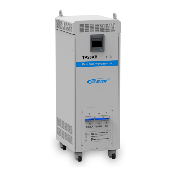
- Page 1 TPower Series ——Pure Sine Wave Inverter User Manual Models: TP10K-110/220-1 TP10KB-110/220-1 TP10K-220/220-1 TP10KB-220/220-1 TP20K-220/220-1 TP20KB-220/220-1 TP30K-220/220-1 TP30KB-220/220-1...
-
Page 3: Table Of Contents
Contents Important Safety Instructions ....................1 1. Product Overview........................ 5 1.1 Information & Features ..................... 5 1.2 Structure ........................6 1.3 Name definition ......................9 1.4 Connection schematic diagram ................9 1.5 Electrical schematic diagram ................. 10 2. Installation .......................... 11 2.1 Warning ........................ -
Page 4: Important Safety Instructions
Important Safety Instructions Please reserve this manual for future review. This manual contains all the instructions about safety, installation, and operation for TPower series pure sine wave inverter (hereinafter referred to as the inverter). Explanation of symbols To enable the user to use the product efficiently, as well as to ensure personal and property safety, this manual provides related information and emphasize the following symbols. - Page 5 Symbols of inverter WARNING: The entire system should be installed by professional and technical personnel. 2. Requirements for professional and technical personnel: Professionally trained; Familiar with related safety specification for the electrical system; Read this manual carefully, and master related safety cautions. 3.
- Page 6 WARNING: The inverter is only allowed for stand-alone operation, and it is prohibited to connect multiple units’ output in parallel or in series; otherwise the inverter would be damaged. 5. Safety cautions for mechanical installation: WARNING: Before installation, must make sure the inverter has no electrical connection.
- Page 7 9. Safety cautions for stopping the inverter: Firstly turn off the breakers on the utility input side and AC output side, then turn off the DC switch; After the inverter stop working for five minutes, the internal conductive devices could be touched;...
-
Page 8: Product Overview
1.Product Overview 1.1Information & Features TPower series is designed aspure sine wave power frequency inverter, whichconverts 110/220VDC to220/230VAC.Thisdevice consists of a DC-AC inverting module and AC-AC bypass module in parallel, also featuredwithhigh reliability, high efficiency, concise appearance, full protection, easy installation operationfunctions. -
Page 9: Structure
AC OUT button controls the AC output individually 1.1 times overload operation capability Smart fan control reduces energy consumption and noise Use popular semiconductor modules with high reliability and low power consumption Designed with remote switch & RS485 communication interface to achieve the features of remote monitoring and hardware Stop&Start, also the Wi-Fi and Bluetooth communication modules are selectable ... - Page 10 Junction box cover plate To cover the terminals and circuit breakers. ❸ ⑴ To fixed the inverter ❹ Pedestal Input/output circuit breaker Protective devices for turning off the current ❺ ⑵ safely. group For wiring connection with utility, battery, load and ⑵...
- Page 11 1-Red ON/OFF 2-White 3-Yellow +5Vdc 4-Black 5-Blue 485A 6-Green 485B ★Interface connection method : (3)DC fan and AC fan DC fan 2 pieces: When the radiator temperature rises to 45℃ above, the DC fans will start; when the radiator temperature declines to 35℃ below, the DC fans will stop . IMPORTANT: DC fans have the self-checking function when the inverter is powered on, the DC fans would run for three seconds automatically.
-
Page 12: Name Definition
1.3Name definition 1.4Connection schematic diagram WARNING: The AC equipment must be determined according to the output power of the inverter. Do not connect the load in excess of the inverter’s maximum input power, otherwise, the inverter may be damaged. -
Page 13: Electrical Schematic Diagram
1.5Electrical schematic diagram... -
Page 14: Installation
2. Installation 2.1 Warning Please read the manual carefully to get familiar with the installation steps before installation. Be very careful when installing the batteries, especially flooded lead-acid battery. Please wear eye protection, and have fresh water available to rinse if any contact with battery acid. -
Page 15: Instructions
TP20KB 35mm /2AWG AC/2P—100A TP30KB 50mm /0AWG AC/2P—150A Wire and circuit breaker selection for battery Model Battery wire size Breaker TP10K 35mm /2AWG(110VDC) DC/2P—125A TP10KB 25mm /4AWG(220VDC) DC/2P—63A TP20K 35mm /2AWG DC/2P—125A TP20KB TP30K 50mm /0AWG DC/2P—200A TP30KB Wire and circuit breaker selection for AC output Model AC wire size... - Page 16 Step3:Take down the junction box cover plate with special tools. Step4:Wiring...
- Page 17 Mobile APP(For Android only) Download software:www.epever.com—EPEVER(TP) Communication cable: LLT-HNJD-M12GM-1000-6P-PIN Modules: eBox-WIFI-01 and eBox-BLE-01 PC Software Download software:www.epever.com—Inverter Monitor(TP) Communication cable:LLT-HNJD-M12GM-1000-6P-PIN Modules: eBox-WIFI-01 and eBox-BLE-01. Step6:Double check the reliability of wiring connections. Step7:Put on the cover plate. Indicator:Inverter indicator on solid...
- Page 18 LCD: Step8:Close the bypass circuit breaker The indicator:utility indicator on solid LCD: Step9:Close the load circuit breaker LCD: Step10:Inverter output Method 1: Press the “AC output” button for 3 seconds, the inverter would start the output. Method 2: Connect the remote switch, short-circuit the cable 1(red) and cable 2(white) of the remote switch and RS485 communication interface, the inverter would start the output.
- Page 19 Indicator:Inverter indicator slowly flashing and load indicator on solid. LCD: Step11:Turn on the load LED indicators: Inverter and load indicators are slowly flashing. CAUTION: In case the power is supplied to the different AC loads, it is suggested to turn on the loads with larger surge current first, till the load working well, then turn on the loads with smaller surge current.
-
Page 20: Output Voltage/Frequency Grade Switch
2.4Output voltage/frequency grade switch When the dial switch 1 is placed to the ON side, the output frequency is 60Hz, otherwise it is 50Hz, When the dial switch 2 is placed to the ON side, the output voltage is 230VAC, otherwise it is 220VAC. Operating steps: Open the cover plate on the inverter right side, find the dial switches on the control board which is located on the top left corner, see above picture. -
Page 21: Interface
3. Interface 3.1Indicator Indicator Color Status Instruction No utility input On Solid Utility input but no load Utility Green Slowly Flashing(0.5Hz) Utility bypass with load Fast Flashing(2.5Hz) Utility fault Inverter OFF On Solid Inverter Priority Inverter Green Slowly Flashing(0.5Hz) Inverter working Fast Flashing(2.5Hz) Inverter fault Bypass OFF... -
Page 22: Buzzer
3.2 Buzzer Buzzer Instruction No beep No operation and fault One beep Operation succeed Buzzer beep every10s Fault prompt Buzzer beep every1s Fault warning 3.3 Buttons Button Operation Instruction Press the button Return the voltage interface quickly Inverter/Bypass Press the button Switch the inverter and bypass mode and hold on 3s Browse the Utility/Battery/Load column... -
Page 23: Icon
❶ Utility ❻ Fault code ❷ Battery ❼ AggConsum Utility parameters ❸ ❽ Load status Voltage/Current/Power/Frequency Battery parameters ❹ ❾ System running in bypass status Voltage/Current/Power ❿ Load parameters ❺ System running in inverter status Voltage/Current/Power/Frequency 3.4 Icon Icon Instruction Icon Instruction Load≤25%... - Page 24 Switch from inverter mode to bypass mode Operation: Press “inverter/bypass” buttonfor 3seconds, bypass indicator changes from off to solid on, inverter indicator changes from on solid to off. 3)Clear electricity mode Operation: Press“inverter/bypass” and “browse” buttonfor 3seconds together to clear the accumulated consumed electricity.
-
Page 25: Protection
4.Protection Protection Phenomenon Protection Recovery Input reverse When DC input reverses polarity, the The equipment would not be polarity Back to normal after correction. LCD would be off. damaged. protection Inverter mode: Inverter stop working, auto switch to DCinput voltage exceeds bypass mode, AC output continues (If When the input voltagebacks to 146Vdc(110Vdc)/293Vdc(220Vdc) - Page 26 power by 1.1times Fault code“OOL” Buzzer sounds in short cycle Recover the output after the load Shut off the output immediately, auto short circuit failure is cleared recover the output for three times(The The equipment would auto-recover Fault code“OSC” Output short first time delay for 5 seconds, second the output every 24 hours after the circuit...
- Page 27 Fault code“BLV” Buzzer sounds in long cycle Bypass mode: Bypass input voltage lower than Auto switch to inverter mode, AC When the bypass input voltage 176Vac. output continues (if the inverter circuit backs to normal, fault warning stops, Fault code“BLV” has fault too, AC output will stop).
-
Page 28: Troubleshooting
5.Troubleshooting Fault Working Category Fault LED indicators Buzzer Status Troubleshooting Code mode Input reverse LCD screen Correct the wire connection of DC input — — — — polarity polarity. Inverter Inverter indicator Check if the DC input voltage exceeds mode fast flashing 146Vdc(110Vdc)/293Vdc(220Vdc).;... - Page 29 (1) After power off, check if the load is Inverter indicator short circuit. Inverter fast flashing (2) Five minutes after powered off,open IGBT over current Locked up mode Fault indicator the left side cover plate, check if the on solid IGBT screw or wire connection is loose;...
-
Page 30: Maintenance
6.Maintenance The following inspections and maintenance tasks are recommended at least two times per year for the best performance. Make sure no block on air-flow around the inverter. Clear up any dirt and fragments on the radiator. Check all the naked wires to make sure insulation is not damaged for serious solarization. -
Page 31: Specifications
7. Specifications Technical parameters Item TP10K-110/220-1 TP10KB-110/220-1 TP10K-220/220-1 TP10KB-220/220-1 110Vdc 220Vdc Rated input voltage 93-146Vdc Battery Input voltage range 187~293Vdc Max. input current 122A Rated output power 10000VA Output voltage 220/230Vac±3%(Battery power mode) Output frequency 50Hz/60Hz±3%(Battery power mode) Output power factor 0.2~1 Output way Single phase... - Page 32 Output way Single phase Output wave Pure Sine Wave ≤3%(Resistive load) Output THD >90%(Resistive rated load) Max. inverter efficiency Bypass Input voltage range — — 170VAC~275VAC 170VAC~275VAC Bypass transfer time 12mS ≤2% No load consumption Backlight 30S(Turn on by pressing the button) Environmental parameters Operating temperature -25℃~50℃(Derating above 45℃)★...
- Page 33 ★Instruction for inverter derating 1. Temperature derating: When the temperature is over 45℃(113℉), the output power shouldbe reduced by 1KW (Kilowatts) for each 1℃ (Celsius) increase TP10K,TP10KB TP20K,TP20KB TP30K,TP30KB...
- Page 34 2.Altitude derating: When the altitude is over 1500m, the output power should be reduced by 1KW (Kilowatts) for each 500m (Meter) increase TP10K,TP10KB TP20K,TP20KB TP30K,TP30KB...
-
Page 35: Annexⅰdisclaimer
Mechanical Parameters TP10K-110/220-1 TP10K- 220/220-1 Item TP10KB-110/220-1 TP10KB- 220/220-1 Dimension(L×W×H) 600×450×1294mm Packaging(L×W×H) 680×500×1410mm Wiring(L×W) 900×1050mm Weight 150Kg 148Kg TP20K-220/220-1 TP30K-220/220-1 Item TP20KB-220/220-1 TP30KB-220/220-1 Dimension(L×W×H) 600×450×1414mm 600×480×1444mm Packaging(L×W×H) 680×500×1530mm 680×530×1560mm Wiring(L×W) 900×1050mm 900×1080mm Weight 188Kg 228Kg AnnexⅠDisclaimer This warranty does not apply under the following conditions: ... -
Page 36: Annexⅱ Mechanical Dimension Diagram
AnnexⅡ Mechanical Dimension Diagram 1.TP10K,TP10KB... - Page 37 2.TP20K/TP20KB...
- Page 38 3.TP30K/TP30KB Any changes without prior notice! Version number: V1.0...
- Page 40 BEIJING EPSOLAR TECHNOLOGY CO., LTD. Tel: +86-10-82894896 / 82894112 Fax: +86-10-82894882 E-mail:info@epsolarpv.com Website: www.epever.com...
Need help?
Do you have a question about the TPower Series and is the answer not in the manual?
Questions and answers