Advertisement
Quick Links
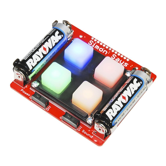
Simon
Kit Information & Instructions
Red then green...no, blue?...wait!...BUZZ! Remember the classic game of Simon?
Well, we have a build-your-own Simon kit that will sharpen your reaction time
while teaching you basic soldering (a useful skill in its own right).
After you have successfully built a working Simon game, you will have a
greater knowledge of through-hole soldering and the tools, techniques, and
terminology required to populate your own PCB prototype. Additionally, the source
code and design files are available, making this project a great entryway into
microcontrollers and embedded programming. Game on!
Kit includes:
• ATMega microcontroller
• Buzzer
• 0.1μF Cap (qty: 2)
• 10K Resistor
• LEDs (qty: 4)
• Slide Switch (qty: 2)
• Battery Clips (qty: 4)
• AA Batteries (qty: 2)
• Button pad
• Bezel
• Standoffs and screws (qty: 4)
• Simon PCB board
Page 1
Advertisement

Related Manuals for sparkfun Simon 10547


Summary of Contents for sparkfun Simon 10547
- Page 1 Simon Kit Information & Instructions Red then green...no, blue?...wait!...BUZZ! Remember the classic game of Simon? Well, we have a build-your-own Simon kit that will sharpen your reaction time while teaching you basic soldering (a useful skill in its own right). After you have successfully built a working Simon game, you will have a greater knowledge of through-hole soldering and the tools, techniques, and terminology required to populate your own PCB prototype.
-
Page 2: Soldering Tips
SOLDERING TIPS Don’t: Use the very tip of the iron. Use the side of the tip of the iron, “The Sweet Spot.” Touch the iron to the component leg and metal ring at the same time. While continuing to hold the iron in contact with the leg and metal ring, feed solder into the joint. - Page 3 QUICKSTART - YOUR FIRST COMPONENT [ STEPS 1 T0 11 ] Locate the 10K Resistor. Bend the legs downward. Locate the 10K Resistor position on the board. Page 4...
- Page 4 QUICKSTART - YOUR FIRST COMPONENT [STEPS 1 T0 11] [ STEPS 1 T0 11 ] Flip the board over. Hold the soldering iron’s “Sweet Spot” so it touches both the leg and the metal ring. Hold for 2 seconds. Feed solder into the joint. Page 6...
- Page 5 CONTINUE WITH THE BOTTOM OF THE BOARD [ STEPS 12 T0 14 ] Now that you’ve successfully soldered in the resistor, use the same method to place and solder the rest of the components. Steps highlighted with a yellow warning triangle represent a polarized component.
- Page 6 NOW WORK ON THE TOP OF THE BOARD [ STEPS 15 T0 17 ] Remember highlighted components are polarized. LEDs (indicator lights): Insert the four LEDs into the front of the board. Each LED has a short leg and a long leg. The short leg goes into the hole labeled “...
-
Page 7: Final Assembly
FINAL ASSEMBLY [ STEPS 18 T0 21 ] No screwdriver necessary. Please only hand-tighten the screws and standoffs. Button Pad (game control): Attach to top. Lay rubber button pad over LEDs. Button Pad Bezel (holds button pad): Attach to top. Lay bezel over button pad, with notches for the screws pointing up. - Page 8 You can write code to change your Simon into a new unique project. To learn more, please check out our online tutorial here: sparkfun.com/tutorials/203 And for even more fun stuff go here: learn.sparkfun.com Page 14...
-
Page 9: Troubleshooting Leds
TROUBLESHOOTING LEDS TROUBLESHOOTING LEDS Failing LEDs? Don’t fret, there is an easy way to fix it! The most common cause of a failing LED is incorrect polarity. We have designed a special trick into the Simon PCB. You can simply cut the two traces and close two jumpers. - Page 10 TROUBLESHOOTING JUMPERS Did you accidentally solder a jumper between two legs? Don’t fret! Here is a simple process using solder wick to remove the excess solder. Locate a piece of solder wick. Page 18...
-
Page 11: Learning More
© SparkFun Electronics, Inc. All Rights Reserved. The SparkFun Simon PTH Kit features, specifications, system requirements, and availability are subject to change without notice. All other trademarks contained herein are the property of their respective owners. - Page 12 Development Boards & Kits - AVR Click to view products by manufacturer: SparkFun Other Similar products are found below : 3264 ATAVRPARROT ATSAMR21B18MZ210PAT CS-EASE-03 EV35F40A A100053 ARDUINO MKR ENV SHIELD REV2 ARDUINO PORTENTA BREAKOUT TPX00031 SENSOR KIT ARDUINO ETH SHIELD 2 WITHOUT POE 1222 MIKROE-2474 1260...
Need help?
Do you have a question about the Simon 10547 and is the answer not in the manual?
Questions and answers