
Subscribe to Our Youtube Channel
Related Manuals for Wabtec RICON KlearVue K Series


Summary of Contents for Wabtec RICON KlearVue K Series
- Page 1 KlearVue ™ K-Series Folding Platform ® DOT – Public Use Lift SERVICE MANUAL 32DSSK06.D 2018 RICON CORPORATION 12/12/18 All Rights Reserved U.S. and foreign patents pending Printed in the United States of America...
- Page 2 K-SERIES PUBLIC USE SERVICE MANUAL TABLE OF CONTENTS DECEMBER 2018 This Ricon service manual is for use by qualified service technicians, and is not intended for use by non-professionals (do-it-yourselfers). The man- ual provides essential instructions and reference information, which sup- ports qualified technicians in the correct installation and maintenance of Ricon products.
- Page 3 K-SERIES PUBLIC USE SERVICE MANUAL TABLE OF CONTENTS DECEMBER 2018 REVISION RECORD PAGES DESCRIPTION OF CHANGE Update to K-Series cover Update address, website, logo. Update to Figure 1-1 to add item 25 for Armored Cable and Cover. Added Armored Cable and Cover description. 2-16 Added Safety Checklist for Front Rollstop.
-
Page 4: Table Of Contents
K-SERIES PUBLIC USE SERVICE MANUAL TABLE OF CONTENTS DECEMBER 2018 Chapter Page I. INTRODUCTION ........................1-1 A. WARRANTY INFORMATION ......................1-2 B. SHIPMENT INFORMATION ....................... 1-3 C. GENERAL SAFETY PRECAUTIONS ....................1-3 D. MAJOR COMPONENTS ........................1-4 II. INSTALLATION ........................2-1 A. - Page 5 K-SERIES PUBLIC USE SERVICE MANUAL TABLE OF CONTENTS DECEMBER 2018 This page intentionally left blank. 32DSSK06.D...
-
Page 6: Introduction
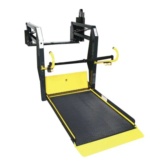
K-SERIES PUBLIC USE SERVICE MANUAL INTRODUCTION DECEMBER 2018 K-SERIES PUBLIC INTRODUCTION ® he RICON K-Series Public Use wheelchair lift provides wheelchair access to vans and buses. The patented movement provides smooth, safe entry and exit, and can lift up to 800 pounds (364 kilograms). The platform is raised with an electro-hydraulic pump. - Page 7 K -SERIES PUBLIC USE SERVICE MANUAL INTRODUCTION DECEMBER 2018 RICON FIVE-YEAR LIMITED WARRANTY RICON K-SERIES ® PUBLIC FIVE-YEAR LIMITED WARRANTY Ricon Corporation (Ricon) warrants to the original purchaser of this product that Ricon will repair or replace, at its option, any part that fails due to defective material or workmanship as follows: •...
-
Page 8: Shipment Information
K-SERIES PUBLIC USE SERVICE MANUAL INTRODUCTION DECEMBER 2018 SHIPMENT INFORMATION Because of the specialized nature of this product, Ricon does not sell directly to the user. Instead, the product is distributed through a woldwide network of authorized Ricon dealers, who perform the actual installation. ... -
Page 9: Major Components
K -SERIES PUBLIC USE SERVICE MANUAL INTRODUCTION DECEMBER 2018 MAJOR LIFT COMPONENTS The terms used throughout this manual are illustrated in Figure 1-1 and defined in Table 1-1. Refer to the parts dia- grams and lists in Chapter IV for more details. RSM008050 1 - 4 32DSSK06.D... - Page 10 K-SERIES PUBLIC USE SERVICE MANUAL INTRODUCTION DECEMBER 2018 TABLE 1-1: K-SERIES MAJOR COMPONENT TERM DEFINITIONS TERM DESCRIPTION Left, right, front, rear Position references when installed lift is viewed from outside of vehicle. Baseplate Bolts to vehicle floor; provides secure foundation for lift structure. Bridgeplate Plate that bridges gap between platform and baseplate when platform is at floor level.
- Page 11 K -SERIES PUBLIC USE SERVICE MANUAL INTRODUCTION DECEMBER 2018 This page intentionally left blank. 1 - 6 32DSSK06.D...
-
Page 12: Installation
K-SERIES PUBLIC USE SERVICE MANUAL DECEMBER 2018 INSTALLATION INSTALLATION ® his chapter contains instructions for installing the RICON K-Series Public Use wheelchair lift into most vans and busses, although custom installations are also possible in other types of vehicles. Due to the wide range of lift applications, specific information for every possible application is not available. -
Page 13: Lift Installation Into Vans
K-SERIES PUBLIC USE SERVICE MANUAL INSTALLATION DECEMBER 2018 Refer to Figure 2-2. On Ford van installations, clamping bars are used to help evenly distribute floor loading and should only be cut if needed to clear a subframe member. A subframe member must be used to support clamping bar. - Page 14 K-SERIES PUBLIC USE SERVICE MANUAL DECEMBER 2018 INSTALLATION d. Refer to Figure 2-4. With doors fully open, position lift in vehicle doorway so that back of lift is supported by vehicle floor, and front of lift is supported by both bracket assemblies. LIFT FRONT LIFT REAR BRACKET ASSEMBLY...
- Page 15 K-SERIES PUBLIC USE SERVICE MANUAL INSTALLATION DECEMBER 2018 VEHICLE REAR VEHICLE FRONT RSM0004400 FIGURE 2-6: STEPWELL BRACKET HOLE LOCATIONS g. Fasten Bracket Assemblies and Lift: 1) Use 1-1/2" x 5/16" sheet metal screws with 5/16" lock washers to secure lower brackets to vehicle step holes 10 through 13.
-
Page 16: Lift Installation Into Busses
K-SERIES PUBLIC USE SERVICE MANUAL DECEMBER 2018 INSTALLATION LIFT INSTALLATION INTO BUSES Refer to Figure 2-7. Clamping bars are used on most bus installations to help distribute floor loading and should be cut only if needed to clear a subframe member. Use the flange of a subframe member to support the clamping bar. VEHICLE FLOOR (BAR) SUBFRAME... -
Page 17: Electrical Installation
K-SERIES PUBLIC USE SERVICE MANUAL INSTALLATION DECEMBER 2018 ELECTRICAL INSTALLATION CAUTION Do not route any wire while it is connected to the battery. Route wires clear of moving parts, brake lines, and the exhaust system. Secure to the vehicle. ... -
Page 18: Install Main Circuit Breaker
K-SERIES PUBLIC USE SERVICE MANUAL DECEMBER 2018 INSTALLATION INSTALL MAIN CIRCUIT BREAKER a. Disconnect battery. b. Mount main circuit breaker inside engine compartment within 12 inches of battery (to minimize length of un- protected cable). Avoid installing near a heat source. ROUTE AND CONNECT MAIN POWER CABLE CAUTION Check under-side of vehicle before drilling to avoid damage to fuel lines, vent lines, brake lines, or wiring. -
Page 19: Connect Control Pendant
K-SERIES PUBLIC USE SERVICE MANUAL INSTALLATION DECEMBER 2018 Refer to Figure 2-9. Cut excess wire from long cable, install heavy ring terminal, and then connect to side solenoid. Verify that red wire from main circuit breaker (if applicable) is connected to positive solenoid pole. POSITIVE CONNECTION BLOCK TERMINAL INSTALL BOOT (KIT 37152) -
Page 20: Ground (Common) Connections
K-SERIES PUBLIC USE SERVICE MANUAL DECEMBER 2018 INSTALLATION 4. GROUND (COMMON) CONNECTIONS 12VDC Systems 12VDC powered lifts are chassis grounded and do not require a separate ground cable connection to battery. However, if the common side of the lift electrical system is connected to chassis with a cable, the cable must be attached in a manner that provides a reliable electrical connection. -
Page 21: Interlock Device Installation
K-SERIES PUBLIC USE SERVICE MANUAL INSTALLATION DECEMBER 2018 5. INTERLOCK DEVICE INSTALLATION The supplied interlock device must be installed to prevent operation of the lift or vehicle when it is unsafe to do so. The K-series lift provides an electrical interlock signal to the vehicle that prevents movement of the vehicle unless the platform is fully stowed. - Page 22 K-SERIES PUBLIC USE SERVICE MANUAL DECEMBER 2018 INSTALLATION a. Fully DEPLOY platform. b. Adjust UP CUTOFF ADJUSTMENT SCREW and DEPLOY CUTOFF ADJUSTMENT SCREW 6-8 turns counterclockwise and then push screws FORWARD. c. Cycle platform to STOW then DEPLOY. d. When in DEPLOY position, platform should stop at an angle and NOT even with vehicle floor. If not, turn DEPLOY CUTOFF ADJUSTMENT SCREW an additional 2-3 turns counterclockwise, push screw for- ward, STOW then DEPLOY platform, then repeat this step.
-
Page 23: Platform Tilt Adjustment
K-SERIES PUBLIC USE SERVICE MANUAL INSTALLATION DECEMBER 2018 TABLE 2-1: LIMIT SWITCH ADJUSTMENT CHART CORRECTIVE COMPONENT SYMPTOM ADJUSTMENT PROCEDURE ACTION Up cutoff Lift stops low. Adjust screw clock- Adjust up cutoff switch so that lift stops just adjustment wise. before first knuckle actuator saddle or roller screw touches underside of lower parallel arm. -
Page 24: Platform Folding Linkage Adjustment
K-SERIES PUBLIC USE SERVICE MANUAL DECEMBER 2018 INSTALLATION 2. PLATFORM FOLDING LINKAGE ADJUSTMENT The front portion of the platform is connected to the rear portion with a hinge. The front portion is folded with link- ages located at the right and left sides of the platform. The length of the linkage might require adjustment after in- stallation of the lift or after disassembly of the platform. -
Page 25: Platform Pressure Switch Check And Adjustment
K-SERIES PUBLIC USE SERVICE MANUAL INSTALLATION DECEMBER 2018 3. PLATFORM PRESSURE SWITCH CHECK AND ADJUSTMENT Correct adjustment of this pressure switch will prevent platform from folding into vehicle when there is a load of 50 lbs, or more, on the platform. a. - Page 26 K-SERIES PUBLIC USE SERVICE MANUAL DECEMBER 2018 INSTALLATION FIGURE 2-19: ALTERNATE 50 LB. WEIGHT d. The pressure switch is correctly set if pump motor shuts off when attempting to stow the lift, preventing in- ward movement of the platform. e. The pressure switch is not correctly set if pump motor does NOT shut off and there is inward movement of the platform.
-
Page 27: Verify Installation
K-SERIES PUBLIC USE SERVICE MANUAL INSTALLATION DECEMBER 2018 VERIFY INSTALLATION Be certain that no vehicle components interfere with operation of lift. The lift is designed to carry the weight of a wheelchair and its passenger. The vehicle structure must be capable of supporting all loads produced during lift operation as well as those forces caused by motion of vehicle when it is driven. - Page 28 K-SERIES PUBLIC USE SERVICE MANUAL DECEMBER 2018 INSTALLATION PART OF SERIAL NUMBER PART OF SERIAL MANUAL OPERATION CORPORATION CORPORATION 7900 Nelson Road, Panorama City, CA 91402 NUMBER DECAL DECAL (LOCATED ON 7900 Nelson Road, Panorama City, CA 91402 mfg. date: Made in U.S.A.
- Page 29 K-SERIES PUBLIC USE SERVICE MANUAL INSTALLATION DECEMBER 2018 This page intentionally left blank. 2 - 18 32DSSSK06.D...
-
Page 30: Maintenance And Repair
K-SERIES PUBLIC USE SERVICE MANUAL MAINTENANCE DECEMBER 2018 III. MAINTENANCE AND REPAIR ® egular maintenance of the Ricon K-Series Public Use wheelchair lift will optimize its performance and reduce the need for repairs. This chapter contains lubrication and cleaning instructions, a maintenance schedule, trouble- shooting section, and maintenance diagrams. -
Page 31: Cleaning
MAINTENANCE K-SERIES PUBLIC USE SERVICE MANUAL DECEMBER 2018 CLEANING Regular cleaning with mild soap (i.e. hand soap, car wash liquid) and drying thoroughly will protect lift painted surfaces. Cleaning is especially important in areas where roads are salted in winter. Make sure that lift pivot points remain clear and clean prior to lubrication. -
Page 32: Troubleshooting
K-SERIES PUBLIC USE SERVICE MANUAL MAINTENANCE DECEMBER 2018 TABLE 3-1: MAINTENANCE SCHEDULE SERVICE POINT ACTION TO PERFORM Check hydraulic cylinder for evidence of leaks. Hydraulic cylinder, hoses and fittings Inspect hydraulic hoses for damage. Verify that all fittings are tight. ... -
Page 33: Pump Solenoid Led Status Indicator
MAINTENANCE K-SERIES PUBLIC USE SERVICE MANUAL DECEMBER 2018 Hydraulic fluid may be While platform is at GROUND LEVEL, be certain that low. pump hydraulic fluid level is maintained at required FULL level. Add only Texaco 01554 Aircraft Hydraulic Oil or equivalent U.S. - Page 34 K-SERIES PUBLIC USE SERVICE MANUAL MAINTENANCE DECEMBER 2018 5) Route the cable around the IRS pulley mount block bushing (#2). Verify that cable is routed between the bushing tab and the point where the cable makes contact with the bushing. Install washer and hex nut over bushing and cable assembly.
-
Page 35: Limit Switch States
MAINTENANCE K-SERIES PUBLIC USE SERVICE MANUAL DECEMBER 2018 FIGURE 3-3: BRIDGEPLATE CABLE ROUTING LIMIT SWITCH STATES Refer to Figure 3-4. The limit switch actuation chart shows the state of all limit switches as the platform travels from stowed, to vehicle floor level, and then to ground level. The solid line segments (▬) represent current flow through the normally CLOSED switch contacts, and the open line segments (═) represent current flow through the normally OPEN switch contacts. -
Page 36: Hydraulic Circuit Diagram
K-SERIES PUBLIC USE SERVICE MANUAL MAINTENANCE DECEMBER 2018 HYDRAULIC CIRCUIT DIAGRAM FIGURE 3-5: K-SERIES HYDRAULIC CIRCUIT DIAGRAM 3 - 7 32DSSK06.D... -
Page 37: Electrical Wiring Diagram
MAINTENANCE K-SERIES PUBLIC USE SERVICE MANUAL DECEMBER 2018 ELECTRICAL WIRING DIAGRAM DIAGRAM LEGENDS Wire Color Codes TABLE 3-3: WIRE COLOR CODES LETTER COLOR LETTER COLOR Black Blue Violet Brown Gray Green White Orange Yellow END OF TABLE Electrical Connector Description Refer to Figure 3-6. - Page 38 K-SERIES PUBLIC USE SERVICE MANUAL MAINTENANCE DECEMBER 2018 Electrical Symbols Figure 3-8 defines the symbols used on the electrical wiring diagram. FIGURE 3-8: ELECTRICAL WIRING DIAGRAM SYMBOLS 3 - 9 32DSSK06.D...
-
Page 39: Wiring Diagram
MAINTENANCE K-SERIES PUBLIC USE SERVICE MANUAL DECEMBER 2018 WIRING DIAGRAM Refer to Figures 3-9 and 3-10 on the following two pages. The diagram is divided into two sheets. 3 - 10 32DSSK06.D... - Page 40 K-SERIES PUBLIC USE SERVICE MANUAL MAINTENANCE DECEMBER 2018 RED (TOP) MOTOR MOTOR CONTACTOR CONTACTOR (TOP) (SIDE) GRN (SIDE) PLATFORM PRESSURE SWITCH FAST GN 2 PUMP ON DOWN VALVE BK 4 12V-8A P3 J3 SLOW BLOCK DIODES BK 4 LIFT CONTROL STOW STATUS STOW-LOCK...
- Page 41 MAINTENANCE K-SERIES PUBLIC USE SERVICE MANUAL DECEMBER 2018 Rollstop Sensor Pressure Mat Detector RSM0080600 FIGURE 3-10: K-SERIES DOT PUBLIC USE LIFT SCHEMATIC – SHEET 2 3 - 12 32DSSK06.D...
- Page 42 K-SERIES PUBLIC USE SERVICE MANUAL SPARE PARTS DECEMBER 2018 K-SERIES PUBLIC USE SPARE PARTS his chapter contains parts diagrams and lists for the RICON K-Series ® Public Use wheelchair lift. The exploded view of each major lift assembly shows individual components referenced by numbers. On each associated list are reference numbers, part descriptions, quantities used, and RICON part numbers.
- Page 43 SPARE PARTS K-SERIES PUBLIC USE SERVICE MANUAL DECEMBER 2018 PART OF SERIAL NUMBER PART OF SERIAL CORPORATION MANUAL OPERATION CORPORATION 7900 Nelson Road, Panorama City, CA 91402 DECAL (LOCATED ON NUMBER DECAL 7900 Nelson Road, Panorama City, CA 91402 mfg. date: Made in U.S.A.
- Page 44 K-SERIES PUBLIC USE SERVICE MANUAL SPARE PARTS DECEMBER 2018 This page intentionally left blank. 4 - 3 32DSSK06.D...
- Page 45 SPARE PARTS K-SERIES PUBLIC USE SERVICE MANUAL DECEMBER 2018 RSM0040900 FIGURE 4-2: PUBLIC USE PUMP ASSY 4 - 4 32DSSK06.D...
- Page 46 K-SERIES PUBLIC USE SERVICE MANUAL SPARE PARTS DECEMBER 2018 FIGURE 4-2: PUBLIC USE PUMP ASSY FIG. ITEM DESCRIPTION CONFIG. PART NO. KIT, SOLENOID, 12V, SPST 29297 BUS BAR, ISKRA MOTOR 10807 KIT, MOTOR ASSY, W/BRACKET, 12V 14345 KIT, PRESSURE SWITCH, WITH INSTRUCTIONS 42050 LIGHT ASSY, INDICATOR, 12V 19067...
- Page 47 SPARE PARTS K-SERIES PUBLIC USE SERVICE MANUAL DECEMBER 2018 RSM0041001 FIGURE 4-3: PUBLIC USE HYDRAULIC SYSTEM 4 - 6 32DSSK06.D...
- Page 48 K-SERIES PUBLIC USE SERVICE MANUAL SPARE PARTS DECEMBER 2018 FIGURE 4-3: PUBLIC USE HYDRAULIC SYSTEM FIG. ITEM DESCRIPTION CONFIG. PART NO. HANDLE, MANUAL BACKUP PUMP V2-SH-111 KIT, TOOL CLIP, W/HARDWARE 19557 COVER, ASSY, PUMP, LH V2-CV-220 3A * COVER, ASSY, PUMP, RH V2-CV-221 SCREW, HEX, 5/16-18 X 5/8”...
- Page 49 SPARE PARTS K-SERIES PUBLIC USE SERVICE MANUAL DECEMBER 2018 FIGURE 4-3: PUBLIC USE HYDRAULIC SYSTEM CONT’D FIG. ITEM DESCRIPTION CONFIG. PART NO. 28 * GLAND NUT, 1.50”, WITH SEAL 13009 (SUPERSEDED BY 21829) GLAND ASSY (FOR S/N ABOVE 236622) 42305 (SEE KIT 21829) COVER, LIGHT 31783...
- Page 50 K-SERIES PUBLIC USE SERVICE MANUAL SPARE PARTS DECEMBER 2018 This page intentionally left blank. 4 - 9 32DSSK06.D...
- Page 51 SPARE PARTS K-SERIES PUBLIC USE SERVICE MANUAL DECEMBER 2018 BRIDGEPLATE LOAD SENSOR MAIN CIRCUIT BREAKER RSM0080300 FIGURE 4-4: PUBLIC USE ELECTRICAL SYSTEM 4 - 10 32DSSK06.D...
- Page 52 K-SERIES PUBLIC USE SERVICE MANUAL SPARE PARTS DECEMBER 2018 FIGURE 4-4: PUBLIC USE ELECTRICAL SYSTEM FIG. ITEM DESCRIPTION CONFIG. PART NO. CAM, LIFT CONTROL V2-AC-107 SWITCH, LIMIT, FOLD CUTOFF V2-ES-111 BLOCK, FOLD CUTOFF SWITCH OFFSET, 1/4" THICK V2-ES-78 BLOCK, FOLD CUTOFF SWITCH OFFSET, 3/8" THICK V2-ES-79 SPRING, RETAINING, UPPER/LOWER SWITCH BLOCK V2-ES-95...
- Page 53 SPARE PARTS K-SERIES PUBLIC USE SERVICE MANUAL DECEMBER 2018 RSM0041200 FIGURE 4-5: PUBLIC USE PENDANT 4 - 12 32DSSK06.D...
- Page 54 K-SERIES PUBLIC USE SERVICE MANUAL SPARE PARTS DECEMBER 2018 FIGURE 4-5: PUBLIC USE PENDANT FIG. ITEM DESCRIPTION CONFIG. PART NO. KIT, PENDANT, MOUNT 33021 KIT, CTL HARNESS, STRAIN RELIEF, W/U-BOLT 01007 KIT, PENDANT, W/7FT CORD K2003 33022 K2005 33022 K2010-F 33022 K5503-F 33022...
- Page 55 SPARE PARTS K-SERIES PUBLIC USE SERVICE MANUAL DECEMBER 2018 RSM0054201 FIGURE 4-6: PUBLIC USE FOLDING PLATFORM ASSEMBLY 4 - 14 32DSSK06.D...
- Page 56 K-SERIES PUBLIC USE SERVICE MANUAL SPARE PARTS DECEMBER 2018 FIGURE 4-6: PUBLIC USE FOLDING PLATFORM ASSEMBLY FIG. ITEM DESCRIPTION CONFIG. PART NO. KIT, PNEUMATIC SPRING ASSY, RETROFIT (LH & RH SIDE KIT) 19318 SPRING, PNEUMATIC ASSIST R5-SP-502 ROD END ASSY, WITH HARDWARE 29224 KIT, LINK ASSY, RH, YELLOW, 51”...
- Page 57 SPARE PARTS K-SERIES PUBLIC USE SERVICE MANUAL DECEMBER 2018 FIGURE 4-6: PUBLIC USE FOLDING PLATFORM ASSEMBLY (CONT’D) FIG. ITEM DESCRIPTION CONFIG. PART NO. ROLLSTOP ASSY, 6” X 32” K2005 39952 (SUPERSEDED 32445) 10A ** ROLLSTOP ASSY, 6” X 32” K2005 51850290-02 ROLLSTOP ASSY, 6”...
- Page 58 K-SERIES PUBLIC USE SERVICE MANUAL SPARE PARTS DECEMBER 2018 FIGURE 4-6: PUBLIC USE FOLDING PLATFORM ASSEMBLY (CONT’D) FIG. ITEM DESCRIPTION CONFIG. PART NO. KIT, FLANGED BEARING, 1” ID (BAG OF 10) 19579 BLOCK, PLATFORM LEVEL ADJUST VT-AH-142 SCREW, BUTTON HEAD, 5/16-18 X 1/2, SST, BLK OXIDE (BAG OF 10) 1 14484 SCREW, HEX HEAD, 5/16-18 X 1½, GR5 (BAG OF 10) 14403...
- Page 59 SPARE PARTS K-SERIES PUBLIC USE SERVICE MANUAL DECEMBER 2018 This page intentionally left blank. 4 - 18 32DSSK06.D...
- Page 60 K-SERIES PUBLIC USE SERVICE MANUAL SPARE PARTS DECEMBER 2018 RSM0054301 FIGURE 4-7.1: K-SERIES DOT PUBLIC USE TRAVELING FRAME (SHEET 1 OF 2) 4 - 19 32DSSK06.D...
- Page 61 SPARE PARTS K-SERIES PUBLIC USE SERVICE MANUAL DECEMBER 2018 SPRAY PAINT - TOUCH UP RSM0054401 FIGURE 4-7.2: K-SERIES DOT PUBLIC USE TRAVELING FRAME (SHEET 2 OF 2) 4 - 20 32DSSK06.D...
- Page 62 K-SERIES PUBLIC USE SERVICE MANUAL SPARE PARTS DECEMBER 2018 This page intentionally left blank. 4 - 21 32DSSK06.D...
- Page 63 SPARE PARTS K-SERIES PUBLIC USE SERVICE MANUAL DECEMBER 2018 FIGURE 4-7: K-SERIES DOT PUBLIC USE TRAVELING FRAME ASSY FIG. ITEM DESCRIPTION CONFIG. PART NO. ARM ASSY, VERTICAL, RH (GRAY) K2003 19328 ARM ASSY, VERTICAL, RH (GRAY) K2005 19328 ARM ASSY, VERTICAL, RH (GRAY) K2010 19328 ARM ASSY, VERTICAL, RH (GRAY)
- Page 64 K-SERIES PUBLIC USE SERVICE MANUAL SPARE PARTS DECEMBER 2018 FIGURE 4-7: K-SERIES DOT PUBLIC USE TRAVELING FRAME ASSY FIG. ITEM DESCRIPTION CONFIG. PART NO. RETAINER, CAM ROLLER 37729 ROLLER, INNER ROLLSTOP CAM V2-AC-024 PIN, CAM ROLLER V2-PI-094 FLANGED BUSHING, .75ID (BAG OF 10) 19576 RIVET, BLIND, 3/16 X 1/2", ALUM (BAG OF 10) 15918...
- Page 65 SPARE PARTS K-SERIES PUBLIC USE SERVICE MANUAL DECEMBER 2018 FIGURE 4-7: K-SERIES DOT PUBLIC USE TRAVELING FRAME ASSY FIG. ITEM DESCRIPTION CONFIG. PART NO. WASHER, KEYED 20258 KIT, LATCH RELEASE, 30", W/BLOCKS & HARDWARE K2003 28768 KIT, LATCH RELEASE, 30", W/BLOCKS & HARDWARE K5503 28768 KIT, LATCH RELEASE, 32", W/BLOCKS &...
- Page 66 K-SERIES PUBLIC USE SERVICE MANUAL SPARE PARTS DECEMBER 2018 This page intentionally left blank. 4 - 25 32DSSK06.D...
- Page 67 SPARE PARTS K-SERIES PUBLIC USE SERVICE MANUAL DECEMBER 2018 RSM0041501 FIGURE 4-8: PUBLIC USE HANDRAILS 4 - 26 32DSSK06.D...
- Page 68 K-SERIES PUBLIC USE SERVICE MANUAL SPARE PARTS DECEMBER 2018 FIGURE 4-8: PUBLIC USE HANDRAILS FIG. ITEM DESCRIPTION CONFIG. PART NO. BUMPER, RUBBER (BAG OF 10) 20653 CAP, ROUND, BLACK 25550 HANDRAIL ASSY, FMVSS, LH K2003 32476 HANDRAIL ASSY, FMVSS, LH K2005 32476 HANDRAIL ASSY, FMVSS, LH...
- Page 69 SPARE PARTS K-SERIES PUBLIC USE SERVICE MANUAL DECEMBER 2018 This page intentionally left blank. 4 - 28 32DSSK06.D...
- Page 70 K-SERIES PUBLIC USE SERVICE MANUAL SPARE PARTS DECEMBER 2018 APPENDIX 1 LIFT SPECIFICATIONS K-SERIES PUBLIC USE PLATFORM LIFT Power .............. electro-hydraulic Rated load capacity ........800 lbs Motor rating @ 12 volts DC ..65.0 amp. avg/cycle, 1250 psi Manual backup (up) ......hand pump @ 24 volts DC ..
- Page 71 SPARE PARTS K-SERIES PUBLIC USE SERVICE MANUAL DECEMBER 2018 NOTES: 4 - 30 32DSSK06.D...
Need help?
Do you have a question about the RICON KlearVue K Series and is the answer not in the manual?
Questions and answers