Table of Contents
Advertisement
Quick Links
Advertisement
Chapters
Table of Contents

Related Manuals for Cisco Cisco Wide Area Application Engine 612


Summary of Contents for Cisco Cisco Wide Area Application Engine 612
- Page 1 Cisco Wide Area Application Engine 512 and 612 Hardware Installation Guide Americas Headquarters Cisco Systems, Inc. 170 West Tasman Drive San Jose, CA 95134-1706 http://www.cisco.com Tel: 408 526-4000 800 553-NETS (6387) Fax: 408 527-0883 Text Part Number: OL-9137-02...
- Page 2 DAMAGES. CCVP, the Cisco logo, and Welcome to the Human Network are trademarks of Cisco Systems, Inc.; Changing the Way We Work, Live, Play, and Learn is a service mark of Cisco Systems, Inc.; and Access Registrar, Aironet, Catalyst, CCDA, CCDP, CCIE, CCIP, CCNA, CCNP, CCSP, Cisco, the Cisco...
-
Page 3: Table Of Contents
Preface Purpose Audience Organization Conventions Related Documentation Obtaining Documentation Documentation Feedback Cisco Product Security Overview Obtaining Technical Assistance Obtaining Additional Publications and Information Introducing the Cisco Wide Area Application Engine C H A P T E R Introduction Software Functional Description Cisco Wide Area Application Engine 512 and 612 Hardware Installation Guide OL-9137-02 viii... - Page 4 Contents Hardware Features Preparing to Install the Cisco Wide Area Application Engine C H A P T E R Safety Warnings Safety Guidelines Installing the Cisco Wide Area Application Engine C H A P T E R Tools and Parts Required Installing the Cisco Wide Area Application Engine Cisco Wide Area Application Engine 512 and 612 Hardware Installation Guide ACNS Software Description...
- Page 5 Connecting Cables Connecting Power and Booting the System Checking the LEDs Removing or Replacing a Cisco Wide Area Application Engine Installing Hardware Options C H A P T E R Removing the Cover and Bezel Installing Adapters Installing DIMMs Working with Hard Disk Drives Completing the Installation Technical Specifications A P P E N D I X...
- Page 6 Contents Corrosion Electrostatic Discharge Electromagnetic and Radio Frequency Interference Magnetism Power Source Interruptions Using Power Protection Devices Surge Protectors Line Conditioners Uninterruptible Power Supplies N D E X Cisco Wide Area Application Engine 512 and 612 Hardware Installation Guide OL-9137-02...
- Page 7 Preface This preface describes the purpose of the Cisco Wide Area Application Engine 512 and 612 Hardware Installation Guide, who should read it, how it is organized, and its document conventions. This preface contains the following sections: Purpose, page vii •...
-
Page 8: C H A P T E R 3 Installing The Cisco Wide Area Application Engine
Audience installation procedures covered in this guide, you will then use the appropriate companion publications to configure your system. (See the Documentation” section on page Audience To use this installation guide, you should be familiar with internetworking equipment and cabling, and have a basic knowledge of electronic circuitry and wiring practices. -
Page 9: Conventions
Preface Chapter Title Chapter 4 Installing Hardware Options Appendix A Technical Specifications Appendix B Troubleshooting the System Hardware Appendix C Maintaining the Cisco Wide Area Application Engine Conventions Command descriptions use the following conventions: Convention boldface font italic font {x | y | z} [x | y | z] string Cisco Wide Area Application Engine 512 and 612 Hardware Installation Guide... - Page 10 Conventions Screen examples use the following conventions: Convention font screen boldface screen font italic screen font < > !, # Notes, cautionary statements, and safety warnings use these conventions: Means reader take note. Notes contain helpful suggestions or references to Note materials not contained in this manual.
-
Page 11: Related Documentation
Preface Warning IMPORTANT SAFETY INSTRUCTIONS This warning symbol means danger. You are in a situation that could cause bodily injury. Before you work on any equipment, be aware of the hazards involved with electrical circuitry and be familiar with standard practices for preventing accidents. - Page 12 Related Documentation The WAFS software document set includes the following documents: Release Notes for Cisco WAFS • Cisco WAFS 3.0 Quick Installation Guide • Cisco WAFS 3.0 Configuration Guide • Cisco WAFS 3.0 Command Reference • Cisco WAFS 3.0 User Guide •...
-
Page 13: Obtaining Documentation
Preface Obtaining Documentation Cisco documentation and additional literature are available on Cisco.com. Cisco also provides several ways to obtain technical assistance and other technical resources. These sections explain how to obtain technical information from Cisco Systems. Cisco.com You can access the most current Cisco documentation at this URL: http://www.cisco.com/techsupport You can access the Cisco website at this URL: http://www.cisco.com... -
Page 14: Ordering Documentation
URL: http://www.cisco.com/univercd/cc/td/doc/es_inpck/pdi.htm Nonregistered Cisco.com users can order documentation through a local • account representative by calling Cisco Systems Corporate Headquarters (California, USA) at 408 526-7208 or, elsewhere in North America, by calling 1 800 553-NETS (6387). Documentation Feedback You can rate and provide feedback about Cisco technical documents by completing the online feedback form that appears with the technical documents on Cisco.com. -
Page 15: Cisco Product Security Overview
Preface You can submit comments by using the response card (if present) behind the front cover of your document or by writing to the following address: Cisco Systems Attn: Customer Document Ordering 170 West Tasman Drive San Jose, CA 95134-9883 We appreciate your comments. -
Page 16: Reporting Security Problems In Cisco Products
Obtaining Technical Assistance Reporting Security Problems in Cisco Products Cisco is committed to delivering secure products. We test our products internally before we release them, and we strive to correct all vulnerabilities quickly. If you think that you might have identified a vulnerability in a Cisco product, contact PSIRT: Emergencies —... -
Page 17: Cisco Technical Support & Documentation Website
Preface service contract, Cisco Technical Assistance Center (TAC) engineers provide telephone support. If you do not have a valid Cisco service contract, contact your reseller. Cisco Technical Support & Documentation Website The Cisco Technical Support & Documentation website provides online documents and tools for troubleshooting and resolving technical issues with Cisco products and technologies. -
Page 18: Definitions Of Service Request Severity
Preface Obtaining Technical Assistance solutions. If your issue is not resolved using the recommended resources, your service request is assigned to a Cisco engineer. The TAC Service Request Tool is located at this URL: http://www.cisco.com/techsupport/servicerequest For S1 or S2 service requests or if you do not have Internet access, contact the Cisco TAC by telephone. -
Page 19: Obtaining Additional Publications And Information
You can access Packet magazine at this URL: http://www.cisco.com/packet • Internet Protocol Journal is a quarterly journal published by Cisco Systems for engineering professionals involved in designing, developing, and operating public and private internets and intranets. You can access the Internet Protocol Journal at this URL: http://www.cisco.com/ipj... - Page 20 Preface Obtaining Additional Publications and Information World-class networking training is available from Cisco. You can view • current offerings at this URL: http://www.cisco.com/en/US/learning/index.html Cisco Wide Area Application Engine 512 and 612 Hardware Installation Guide OL-9137-02...
-
Page 21: Introducing The Cisco Wide Area Application Engine
Introducing the Cisco Wide Area Application Engine This chapter provides a basic functional overview of the Cisco Wide Area Application Engine 512 and 612 (WAE-512 and WAE-612), and describes the hardware, major components, and front and back panel indicators and controls. This chapter contains the following sections: •... - Page 22 Chapter 1 Introducing the Cisco Wide Area Application Engine Introduction When WAAS software is installed, the WAE appliance can function as either a Central Manager or as an Application Acceleration Engine. When ACNS software is installed, the WAE appliance functions as a Content Engine or one of the other ACNS device modes (Content Router or Content Distribution Manager).
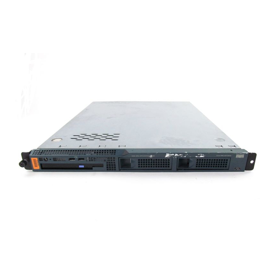
- Page 23 Chapter 1 Introducing the Cisco Wide Area Application Engine Introduction Figure 1-2 WAE-612—Front View The WAE-512 and WAE-612 are configured for AC-input power and have a single AC-input power supply. The WAE appliance has an integrated dual-port Ethernet controller, which supports 10BASE-T/100BASE-TX/1000BASE-TX Ethernet using RJ-45 receptacles.
-
Page 24: Software Functional Description
Software Functional Description Figure 1-3 WAE-512 and WAE-612 Back Panel Software Functional Description The operation of the WAE is dependent on the software application that is installed on it. This section describes WAAS, ACNS and WAFS software: WAAS Software Description, page 1-4 •... -
Page 25: Acns Software Description
Chapter 1 Introducing the Cisco Wide Area Application Engine Migrate application and file servers from branch offices into centrally • managed data centers. Minimize unnecessary WAN bandwidth consumption through the use of • advanced compression algorithms. Provide print services to branch office users. Cisco WAAS allows you to •... -
Page 26: Wafs Software Description
Hardware Features To deploy Cisco Content Engines with Cisco ACNS software within your existing network, your network must support Cisco IOS software and the Web Cache Communication Protocol (WCCP). WCCP transparently redirects HTTP requests to a Content Engine, and the Content Engine responds to those requests. WAFS Software Description With WAFS software installed, the WAE appliance functions as a File Engine. -
Page 27: Front Panel Control Buttons
Chapter 1 Introducing the Cisco Wide Area Application Engine Front Panel Control Buttons Figure 1-4 control buttons. Figure 1-4 Front Panel Control Buttons Power control button CD eject button Table 1-1 Front Panel Control Buttons Item Description Power control button Powers up the device. - Page 28 Hardware Features Figure 1-5 Front Panel LEDs Power on System locator (not supported on Content Engine models) CD-ROM drive activity Table 1-2 Front Panel LEDs Color Power Green Hard disk drive Green activity System error Amber CD-ROM drive Green activity Figure 1-6 their function.
- Page 29 Chapter 1 Introducing the Cisco Wide Area Application Engine Figure 1-6 Back Panel LEDs Ethernet 1 transmit receive activity Ethernet 2 transmit receive activity Table 1-3 Back Panel LEDs Indicator Color Ethernet 1 transmit Green receive activity Ethernet 1 speed Green Ethernet 2 transmit Green...
-
Page 30: Input/Output Ports And Connectors
Hardware Features Input/Output Ports and Connectors Your WAE appliance supports the following I/O connectors on the back of the device: Ethernet connectors • • Serial connector Video and audio connectors (on optional adapter) • To avoid electric shock, do not connect safety extra-low voltage (SELV) circuits Warning to telephone-network voltage (TNV) circuits. - Page 31 Chapter 1 Introducing the Cisco Wide Area Application Engine The system software does not support the use of a keyboard or mouse (Personal Note System 2 [PS/2] or Universal Serial Bus [USB]). The BIOS does support a keyboard and a mouse for power-on self-test (POST) and the configuration/setup utility.
-
Page 32: Ethernet Port Connector
Hardware Features Ethernet Port Connector The WAE appliance comes with one integrated dual-port Ethernet controller. This controller provides an interface for connecting to 10-Mbps, 100-Mbps, or 1000-Mbps networks and provides full-duplex (FDX) capability, which enables simultaneous transmission and reception of data on the Ethernet LAN. To access the Ethernet port, connect a Category 3, 4, or 5 unshielded twisted-pair (UTP) cable to the RJ-45 connector on the back of the device. -
Page 33: Video Port Connectors
Chapter 1 Introducing the Cisco Wide Area Application Engine Figure 1-9 Video Port Connectors The WAE-512 and WAE-612 support one optional MPEG A/V decoder adapter that has one audio and video input/output port. Figure 1-10 input/output port: 3 BNC connectors for YUV, RGB, and composite video output •... -
Page 34: Inline Network Adapter Description
Hardware Features Table 1-5 Pin Number Table 1-6 Pin Number Inline Network Adapter Description This section describes the following features of the WAE inline network adapter: Form and Function • Ports and LED Indicators • Inline Network Adapter Cabling Requirements •... - Page 35 Chapter 1 Introducing the Cisco Wide Area Application Engine Installation Scenarios and Cabling Examples for Fast Ethernet Connections • For adapter specifications, see Form and Function Your appliance supports one optional 4-port Ethernet inline network adapter. The inline network adapter is a full-height, three-quarter-length PCI-X network interface card that contains four independent Gigabit Ethernet ports.
-
Page 36: Ports And Led Indicators
Hardware Features InlineGroup interfaces are numbered using the format slot/group. The slot number is the slot in which the adapter is inserted. (In the WAE 500 series and 600 series appliances, the adapter must be installed in slot 1 only.) The group number is either 0 or 1 (each adapter has 2 group pairs). -
Page 37: Inline Network Adapter Cabling Requirements
Chapter 1 Introducing the Cisco Wide Area Application Engine Port 0; Group 1 WAN interface Port 2; Group 0 WAN interface The inline network adapter has three LEDs that correspond to each port (the 0 LEDs correspond to Port 0, and so forth). Table 1-7 Inline Network Adapter LEDs LEDs... - Page 38 Hardware Features If you are connecting a WAE inline appliance between two devices using Gigabit Ethernet, you can use either straight-through cables, crossover cables, or any combination of the two cable types, regardless of the type of device. However, for consistency, we recommend that you use straight-through cables for all Gigabit Ethernet connections.
- Page 39 Chapter 1 Introducing the Cisco Wide Area Application Engine instructions for the inline network adapter to work properly. (See illustrations and examples, see the for Fast Ethernet Connections” section on page To connect the inline network adapter using the correct cables for Fast Ethernet connections, follow these steps: Determine which type of cable you would use for a direct connection between Step 1...
-
Page 40: Installation Scenarios And Cabling Examples For Fast Ethernet Connections
Hardware Features Table 1-9 Connection Router to WAE and WAE to Router WAE to WAE Connect Fast Ethernet ports on both the LAN and the WAN sides of the WAE Step 2 inline appliance by using the following cable types: On the LAN side of the connection, use a straight-through cable between the •... - Page 41 Chapter 1 Introducing the Cisco Wide Area Application Engine Hardware Features If you are connecting a WAE inline appliance between two devices using Gigabit Ethernet, you can use either straight-through cables, crossover cables, or any combination of the two cable types, regardless of the type of device. This section shows cabling examples for Fast Ethernet connections only, because Fast Ethernet has specific cabling requirements.
- Page 42 Hardware Features Figure 1-13 Cabling for a Single Inline WAE with Redundant WAN Connections LAN switch Connection: Management Gigabit Ethernet: 1/0 Cable type: Straight-through (recommended) Connection: WAE to LAN switch (using InlineGroup 1/1) Fast Ethernet: LAN1 (InlinePort 1/1/lan) Cable type: Straight-through Connection: WAE to WAN router B (using InlineGroup 1/1) Fast Ethernet: WAN1 (InlinePort 1/1/wan)
- Page 43 Chapter 1 Introducing the Cisco Wide Area Application Engine Connection: WAE 1 to LAN switch Fast Ethernet: LAN0 (InlinePort 1/0/lan) Cable type: Straight-through Connection: WAE 2 to WAN router Fast Ethernet: WAE 2 WAN0 (InlinePort 1/0/wan) Cable type: Crossover Figure 1-15 Cabling Between Two Inline WAEs LAN switch Cisco Wide Area Application Engine 512 and 612 Hardware Installation Guide...
- Page 44 Hardware Features Connection: WAE 1 to LAN switch Fast Ethernet: WAE 1 LAN0 (InlinePort 1/0/lan) Cable type: Straight-through Connection: WAE 2 to WAN router Fast Ethernet: WAE 2 WAN0 (InlinePort 1/0/wan) Cable type: Crossover Cisco Wide Area Application Engine 512 and 612 Hardware Installation Guide 1-24 Chapter 1 Introducing the Cisco Wide Area Application Engine...
-
Page 45: Chapter 2 Preparing To Install The Cisco Wide Area Application Engine
Preparing to Install the Cisco Wide Area Application Engine This chapter contains important safety information you should know before working with the Wide Area Application Engine (WAE). Use the guidelines in this chapter to ensure your own personal safety and to help protect your device from potential damage. - Page 46 Safety Warnings Before working on a chassis or working near power supplies, unplug the power Warning cord on AC units. Statement 246 Do not work on the system or connect or disconnect cables during periods of Warning lightning activity. Statement 1001 Read the installation instructions before connecting the system to the power Warning source.
-
Page 47: C H A P T E R 2 Preparing To Install The Cisco Wide Area Application Engine
Chapter 2 Preparing to Install the Cisco Wide Area Application Engine This unit is intended for installation in restricted access areas. A restricted Warning access area can be accessed only through the use of a special tool, lock and key, or other means of security. Statement 1017 Warning The plug-socket combination must be accessible at all times, because it serves as the main disconnecting device. -
Page 48: Safety Guidelines
Safety Guidelines This product requires short-circuit (overcurrent) protection, to be provided as Warning part of the building installation. Install only in accordance with national and local wiring regulations. Statement 1045 Warning Installation of the equipment must comply with local and national electrical codes. - Page 49 Chapter 2 Preparing to Install the Cisco Wide Area Application Engine The product has been dropped or damaged. – The product does not operate correctly when you follow the operating – instructions. Keep your system components away from radiators and heat sources. Also, •...
-
Page 50: Protecting Against Electrostatic Discharge
Safety Guidelines Position cables and power cords carefully; route cables and the power cord • and plug so that they cannot be stepped on or tripped over. Be sure that nothing rests on your system components’ cables or power cord. Do not modify power cables or plugs. - Page 51 Chapter 2 Preparing to Install the Cisco Wide Area Application Engine Do not extend more than one device out of the rack at the same time. • Remove the rack doors and side panels to provide easier access during • installation.
- Page 52 Chapter 2 Preparing to Install the Cisco Wide Area Application Engine Safety Guidelines Cisco Wide Area Application Engine 512 and 612 Hardware Installation Guide OL-9137-02...
-
Page 53: Installing The Cisco Wide Area Application Engine
Installing the Cisco Wide Area Application Engine This chapter explains how to install the Cisco Wide Area Application Engine (WAE) 512 and WAE 612 into an equipment rack. It also provides general instructions for installing the device on a table or workbench. This chapter contains the following sections: Tools and Parts Required, page 3-2 •... -
Page 54: Tools And Parts Required
Tools and Parts Required Tools and Parts Required A sliding rail rack-mount kit and cable management assembly is included in your shipping container accessory box. The rack-mount kit is suitable for mounting the device in a 19-inch (48.26-cm) four-post equipment rack. Angle brackets for mounting the device in a two-post rack are also included in your shipping container. -
Page 55: Installing The Chassis In A Two-Post Rack
Chapter 3 Installing the Cisco Wide Area Application Engine Warning To prevent bodily injury when mounting or servicing this unit in a rack, you must take special precautions to ensure that the system remains stable. The following guidelines are provided to ensure your safety: •... -
Page 56: Installing The Chassis In A Four-Post Rack
Installing the Cisco Wide Area Application Engine To install the chassis in a two-post rack, follow these steps: Attach a bracket to one side of the chassis, aligning the front flange of the bracket Step 1 with the hash mark on the side of the chassis. (See Figure 3-2 Installing the Chassis in the Rack Front... - Page 57 Chapter 3 Installing the Cisco Wide Area Application Engine Figure 3-3 Rear of rail Slide rails (2) M6 screws (6) These slide rails come with spring-loaded locking pins at both ends of each rail. To attach the slide rails to an equipment rack, you need to pull back the pin carriage, align the pins with holes in the equipment rack-mounting flange, and release the pin carriage to lock the pins into the rack posts.
- Page 58 Installing the Cisco Wide Area Application Engine On the rear of the rail, press on the two rear tabs, and slide the pin carriage toward • the front of the rail, releasing the latch tab as it catches in place. To prevent the rail-adjustment bracket (labeled 1 in hold it in place with your thumb.
- Page 59 Chapter 3 Installing the Cisco Wide Area Application Engine Ensure that the pins are fully extended through the mounting flange and slide Note rail pin bracket. (See Figure 3-5 Pins extended through the mounting flange and slide rail pin bracket Release tab for the rail-adjustment bracket To secure the front of the slide rail to the equipment rack, align the pins (labeled 1 in...
- Page 60 Installing the Cisco Wide Area Application Engine Figure 3-6 Pins Slide rail pin bracket Repeat these steps for the right slide rail. Make sure that you attach the second Step 5 slide rail at the same rack height as the first one so that the chassis will be level in the rack.
- Page 61 Chapter 3 Installing the Cisco Wide Area Application Engine Figure 3-7 Captive thumbscrews To remove the shipping bracket, press on the release tab Step 7 indicated on the shipping bracket, and remove the shipping bracket from the slide rail. Repeat this step for the other shipping bracket. Store the shipping brackets for future use.
- Page 62 Installing the Cisco Wide Area Application Engine Figure 3-8 Release tab Attach the power cords and the Ethernet cables to the rear of the device. Step 8 cables to the left corner of the chassis (as viewed from the rear) and use the cable straps to secure the cables to the slide rails.
- Page 63 Chapter 3 Installing the Cisco Wide Area Application Engine Leave enough slack in the cables to allow for sliding the device in or out Note of the rack. To transport the rack to another location with the chassis installed, you must Step 9 secure the chassis to the rack.
-
Page 64: Installing The Chassis On A Tabletop
Installing the Cisco Wide Area Application Engine The four-post rack-mounting system is designed for racks that do not have Note pre-threaded holes. If you are using an equipment rack with pre-threaded holes, the pins will not protrude through the rack. Instead, secure the slide rails to the rack by attaching screws through the slide rail pin brackets at both ends of each rail. -
Page 65: Connecting Cables
Chapter 3 Installing the Cisco Wide Area Application Engine To install the chassis on a workbench or tabletop, follow these steps: Remove any debris and dust from the tabletop or workbench, as well as from the Step 1 surrounding area. Also make sure that your path between the device and its new location is unobstructed. - Page 66 Connecting Cables Figure 3-12 AC power receptacle Keyboard connector Monitor connector Ethernet 1 port connector USB 2 port (not supported) 1. Not required for normal operation. Can be used for troubleshooting purposes. The system software does not support the use of a keyboard or mouse (PS/2 or Note USB).
-
Page 67: Connecting Power And Booting The System
Chapter 3 Installing the Cisco Wide Area Application Engine Connecting Power and Booting the System To connect power to the device, follow these steps: Review the information in the Step 1 Plug the AC power cord into the power cord receptacle at the rear of the device. Step 2 (See Figure... - Page 68 Chapter 3 Installing the Cisco Wide Area Application Engine Removing or Replacing a Cisco Wide Area Application Engine Ultimate disposal of this product should be handled according to all national Warning laws and regulations. Statement 1040 To remove a device from your network, power it down, disconnect the power cords and network cables, and physically remove the chassis from the rack.
-
Page 69: Installing Hardware Options
Installing Hardware Options This chapter provides basic instructions for installing hardware options in the Wide Area Application Engine (WAE). These instructions are intended for experienced technicians. This chapter contains the following topics: Removing the Cover and Bezel, page 4-1 • Installing Adapters, page 4-3 •... -
Page 70: Removing The Cover And Bezel
Removing the Cover and Bezel Press the cover release button. (See Step 3 Figure 4-1 Cover release button While holding the cover release button down with your thumb, lift the opposite Step 4 front corner of chassis slightly with your other hand, and using your free thumb, slide the cover back approximately 0.5 inches (1.27 cm);... -
Page 71: Installing Adapters
Chapter 4 Installing Hardware Options Installing Adapters This section provides general information about the system board, riser card, adapters, and PCI-X slot configuration specifications. Use these instructions to install any full-height three-quarter-length PCI-X adapter card. The MPEG decoder adapter is supported in ACNS software only. The inline Note network adapter is supported in WAAS 4.0.7 and later software only. - Page 72 Installing Adapters Disconnect the power cord and then all external cables from the device. Step 3 Remove the device cover. Step 4 Grasp the riser card at the rear edge and lift to remove the riser card assembly. Step 5 (See Figure Figure 4-2...
- Page 73 Chapter 4 Installing Hardware Options Figure 4-3 Installing the Adapter in the Riser Card Assembly Expansion slot bracket Adapter support bracket Riser card assembly Riser card connectors Cisco Wide Area Application Engine 512 and 612 Hardware Installation Guide OL-9137-02 Adapter PCI-X expansion slot 1 PCI-X expanison slot 2 (not supported) Installing Adapters...
-
Page 74: Installing Dimms
Installing DIMMs Touch the static-protective package that contains the adapter to any unpainted Step 8 metal surface on the device, and then remove the adapter from the static-protective package. Avoid touching the components and gold-plated edge connectors on the adapter. Place the adapter, component-side up, on a flat, static-protective surface. - Page 75 Chapter 4 Installing Hardware Options Memory modules are installed on the system board in the DIMM connectors • shown in installed in DIMM connector 1. Install the next module in DIMM connector 3. The third and fourth DIMMs must be installed as a pair in DIMM connectors 2 and 4.
- Page 76 Installing DIMMs When you handle static-sensitive devices, take precautions to avoid damage from Caution static electricity. To install a DIMM, follow these steps: Review the safety information in the Step 1 Step 2 Power off the device and peripheral devices. Disconnect the power cord, and then disconnect all external cables.
-
Page 77: Working With Hard Disk Drives
Chapter 4 Installing Hardware Options To avoid breaking the retaining clips or damaging the DIMM connectors, open Caution and close the clips gently. Insert the DIMM into the connector by aligning the DIMM edges with the slots at each end of the DIMM connector. Firmly press the DIMM straight down into the connector by applying pressure on both ends of the DIMM simultaneously. -
Page 78: Installing Sata Hard Disk Drives
Working with Hard Disk Drives All hard disk drives being used in the WAE should have the same throughput • speed rating. Mixing hard disk drives with different speed ratings will cause all hard disk drives to operate at the lower throughput speed. To maintain proper system cooling, do not operate the device for more than 10 Caution minutes without either a hard disk drive or a filler panel installed in each bay. - Page 79 Chapter 4 Installing Hardware Options Figure 4-6 Note WAE-512. If you have other options to install, do so now; otherwise, go to the Step 8 the Installation” section on page Figure 4-6 Filler panel SATA hard disk drive backplane Cisco Wide Area Application Engine 512 and 612 Hardware Installation Guide OL-9137-02 shows that disk00 is being inserted into the left drive bay in the 4-15.
-
Page 80: Installing An Sas Hard Disk Drive
Working with Hard Disk Drives Installing an SAS Hard Disk Drive The WAE-612 hardware supports hot-swappable SAS hard disk drives; however, Note you must be running WAAS 4.0.13 or a later version to obtain the software support for hot-swapping. If you are running a WAAS version prior to 4.0.13, we recommend that you power down your WAE-612 when swapping or installing new hard disk drives. - Page 81 Chapter 4 Installing Hardware Options Figure 4-7 Drive handle (in open position) Close the drive tray handle. Step 6 Reload the appliance. Step 7 Check the hard disk drive status LED to make sure that the hard disk drive is Step 8 operating correctly.
-
Page 82: Completing The Installation
Completing the Installation Completing the Installation Caution To maintain proper cooling and airflow, install the cover before turning on the device. Operating the device for extended periods (over 30 minutes) with the cover removed might damage device components. To complete the installation, follow these steps: Step 1 Install the cover by placing it into position and sliding it forward. - Page 83 Chapter 4 Installing Hardware Options Completing the Installation Connect all external cables and the power cord to the device, and then plug the Step 3 power cord into a properly grounded electrical outlet. Cisco Wide Area Application Engine 512 and 612 Hardware Installation Guide 4-15 OL-9137-02...
- Page 84 Chapter 4 Installing Hardware Options Completing the Installation Cisco Wide Area Application Engine 512 and 612 Hardware Installation Guide 4-16 OL-9137-02...
-
Page 85: Appendix
Technical Specifications This appendix describes the WAE models listed here: Model Wide Area Application Engine 512 Wide Area Application Engine 612 This appendix contains the following sections: Appliance Specifications, page A-1 • Adapter Specifications, page A-4 • Appliance Specifications Your system software might not support all of the WAE-supported hardware Note features. - Page 86 Appliance Specifications Table A-1 Appliance Features and Specifications Specification Description Microprocessor • • Memory • • Expansion bays Two 3.5-in. (8.89-cm) slim-height bays for hard disk drives Expansion slots Two 64-bit, 100 MHz PCI-X half-length slots (1 low profile, 1 full profile) Hard disk controllers •...
- Page 87 Appendix A Technical Specifications Table A-1 Appliance Features and Specifications (continued) Specification Description Dimensions • • • Weight Maximum weight: 28 lb (12.7 kg) depending on your configuration Electrical input • • • • Ports Supported • • • Temperature •...
-
Page 88: Adapter Specifications
Adapter Specifications Table A-1 Appliance Features and Specifications (continued) Specification Description Altitude Maximum altitude: 6500 ft (2000 m) Acoustical noise • emissions • 1. FSB = front side bus 2. Btu = British thermal unit Adapter Specifications Table A-2 Table A-2 Fibre Channel Adapter Specifications Fibre Channel adapter •... - Page 89 Appendix A Technical Specifications Table A-3 MPEG A/V Decoder Adapter Specifications MPEG A/V decoder Video specifications adapter • • • • • • • 1. S/N = signal-to-noise ratio 2. rms = root mean square 3. IRE = Institute of Radio Engineers 4.
- Page 90 Adapter Specifications Table A-4 Inline Network Adapter Specifications Specification Copper Gigabit Ethernet Specifications IEEE standard Full duplex and half duplex Autonegotiation Data transfer rate General Technical Specifications Interface standard Size PCI connector PCI voltage Weight Operating humidity Operating temperature Storage temperature Cisco Wide Area Application Engine 512 and 612 Hardware Installation Guide Description Gigabit Ethernet, 1000BASE-T...
-
Page 91: Appendix
Troubleshooting the System Hardware If your system is not working as expected, begin troubleshooting using the procedures in this appendix. This appendix guides you through some initial checks and procedures that can solve basic system problems. This appendix contains the following sections: Checking the Basics, page B-1 •... -
Page 92: Checking Connections And Switches
Checking Connections and Switches If the chassis was dropped or damaged while being moved, you should check the system to see if it functions properly. If an external device attached to the system is dropped or damaged, contact your service representative for instructions. (See “Obtaining Technical Assistance”... - Page 93 Appendix B Troubleshooting the System Hardware To check all the connections and switches, follow these steps: Power down the system, including any attached peripherals such as external Step 1 drives. Disconnect all the power cables from their electrical outlets. If the system is connected to a power strip (or power distribution unit), turn the Step 2 power strip off and then on again.
- Page 94 Appendix B Troubleshooting the System Hardware Checking Connections and Switches Cisco Wide Area Application Engine 512 and 612 Hardware Installation Guide OL-9137-02...
-
Page 95: Appendix
Maintaining the Cisco Wide Area Application Engine Proper use of preventive maintenance procedures can keep your system in good operating condition and minimize the need for costly, time-consuming service procedures. This appendix contains maintenance procedures that you should perform regularly. This appendix covers the following maintenance tasks: Maintaining Your Site Environment, page C-1 •... -
Page 96: Temperature
Maintaining Your Site Environment Temperature Temperature extremes can cause a variety of problems, including premature aging and failure of chips or mechanical failure of devices. Extreme temperature fluctuations can cause chips to become loose in their sockets and can cause expansion and contraction of disk drive platters, resulting in read or write data errors. -
Page 97: Humidity
Appendix C Maintaining the Cisco Wide Area Application Engine Humidity High-humidity conditions can cause moisture migration and penetration into the system. This moisture can cause corrosion of internal components and degradation of properties such as electrical resistance and thermal conductivity. Extreme moisture buildup inside the system can result in electrical shorts, which can cause serious damage to the system. -
Page 98: Corrosion
Maintaining Your Site Environment Corrosion The oil from a person’s fingers or prolonged exposure to high temperature or humidity can corrode the gold-plated edge connectors and pin connectors on various devices in the system. This corrosion on system connectors is a gradual process that can eventually lead to intermittent failures of electrical circuits. -
Page 99: Magnetism
Appendix C Maintaining the Cisco Wide Area Application Engine interfere with cordless and low-power telephones. Conversely, RFI from high-power telephones can cause spurious characters to appear on the system’s monitor screen. RFI is defined as any EMI with a frequency above 10 kilohertz (kHz). This type of interference can travel from the system to other devices through the power cable and power source or through the air like transmitted radio waves. -
Page 100: Power Source Interruptions
Maintaining Your Site Environment Power Source Interruptions Systems are especially sensitive to variations in voltage supplied by the AC power source. Overvoltage, undervoltage, and transients (or spikes) can erase data from memory or even cause components to fail. To protect against these types of problems, power cables should always be properly grounded and one or both of the following methods should be used: Use one of the power protection devices described in the... -
Page 101: Using Power Protection Devices
Appendix C Maintaining the Cisco Wide Area Application Engine Using Power Protection Devices A number of devices are available that protect against power problems such as power surges, transients, and power failures. The following sections describe some of these devices. Surge Protectors Surge protectors are available in a variety of types and usually provide a level of protection commensurate with the cost of the device. - Page 102 Appendix C Maintaining the Cisco Wide Area Application Engine Using Power Protection Devices UPS systems range in price from a few hundred dollars to several thousand dollars, with the more expensive units allowing you to run larger systems for a longer period of time when AC power is lost.
-
Page 103: I N D E X
A/V ports description 1-11 ACNS software Content Engine mode AC power receptacle 1-11 AC power cords connecting 3-15 adapters description inline 1-14 installing altitude guidelines specifications back panel LEDs (figure) LEDs (table) ports (table) 1-11 Cisco Wide Area Application Engine 512 and 612 Hardware Installation Guide OL-9137-02 I N D E X bays... - Page 104 Index console connecting to port 3-13 control buttons front panel corrosion preventing damage covers installing 4-15 removing dimensions DIMMs considerations installing disk drives. See hard disk drives dust preventing damage electrical input specifications electromagnetic interference See EMI electrostatic discharge See ESD Cisco Wide Area Application Engine 512 and 612 Hardware Installation Guide IN-2 preventing effects of...
- Page 105 figure LEDs (figure) LEDs (table) functional description hard disk controllers description hard disk drive LED description hard disk drives description 4-10 SATA 4-10 hardware troubleshooting heat dissipation specifications humidity maintenance guidelines specifications I/O connectors 1-10 inline network adapter cabling examples 1-20 Cisco Wide Area Application Engine 512 and 612 Hardware Installation Guide OL-9137-02...
- Page 106 Index magnetism preventing effects of maintenance C-1 to C-6 memory module installing order of installation memory specifications for WAE-512 for WAE-612 microprocessor description MPEG A/V decoder adapter connectors 1-11, 1-13 installing specifications noise emissions specifications PCI-X slots pinouts, MPEG A/V decoder audio and video connectors 1-13 ports...
- Page 107 contents of radio frequency interference. See RFI receptacles power 1-11 reset button description preventing effects of safety general precautions safety warnings SATA 4-10 Serial Attached SCSI hard disk drives serial ports connector pinout 1-12 description 1-11, 1-12 site environment maintenance factors slots specifications specifications...
- Page 108 Index connectors (figure) 1-13 description 1-11 WAAS software description back panel 1-10 front panel installing in a 2-post rack installing in a 4-post rack installing on a tabletop 3-12 maintaining WAE-512 memory specifications WAE-612 memory specfications WAFS software File Engine mode warnings installation WCCP...
Need help?
Do you have a question about the Cisco Wide Area Application Engine 612 and is the answer not in the manual?
Questions and answers