
Related Manuals for G&D HardBoot plus


Summary of Contents for G&D HardBoot plus
- Page 1 Guntermann & Drunck GmbH www.gdsys.de G&D HardBoot plus Installation und Bedienung Installation and Operation A9100092-1.00...
- Page 2 © Guntermann & Drunck GmbH 2008. Alle Rechte vorbehalten. Version 1.00 – 19.02.2008 Firmware: 1.0.0.2 Guntermann & Drunck GmbH Dortmunder Str. 4a 57234 Wilnsdorf Germany Telefon +49 (0) 2739 8901-100 Telefax +49 (0) 2739 8901-120 http://www.GDsys.de sales@GDsys.de i · G&D HardBoot plus...
-
Page 3: Table Of Contents
Sicherheitshinweise ..................1 Die HardBoot-Serie ................... 2 Lieferumfang ....................3 Installation des HardBoot-Systems ..............4 Installation des Mastergeräts HardBoot plus ............4 Optional: Installation eines Slavegeräts HardBoot CCX ..........5 Installation der Software HardBoot view ............... 7 Netzwerkkonfiguration ..................8 Statusanzeigen des HardBoot-Systems ............. -
Page 4: Sicherheitshinweise
! Die HardBoot-Geräte sind ausschließlich für eine Verwendung im Innenbereich ausgelegt. Sie dürfen nicht in feuchten oder übermäßig heißen Umgebungen ein- gesetzt werden. ! Trennen Sie immer beide Stromkabel jedes HardBoot plus bzw. HardBoot CCX vom Stromnetz bevor Sie in die HardBoot-Geräte oder die angeschlossenen Geräte eingreifen. -
Page 5: Die Hardboot-Serie
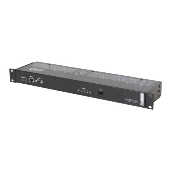
Die HardBoot-Serie Die Remote Power-Switches der HardBoot-Serie erlauben die Stromversorgung von Geräten über das Netzwerk ein- und auszuschalten. Das Mastergerät HardBoot plus ist mit acht Steckdosen (IEC-320) ausgestattet. Über diese Steckdosen können Rechner, Server und andere Geräte mit Strom versorgt werden. -
Page 6: Lieferumfang
2 x Kaltgerätekabel 1 x serielles Datenkabel 1 x Software HardBoot view 1 x Installations- und Bedienhandbuch HardBoot CCX (optionales Slavegerät) 1 x HardBoot CCX 1 x Rackmount-Set 2 x Kaltgerätekabel 1 x Verbindungskabel (x link) 3 · G&D HardBoot plus... -
Page 7: Installation Des Hardboot-Systems
Ausbaustufe des HardBoot-Systems stellt insgesamt 40 Steckdosen zur Verfügung. Installation des Mastergeräts HardBoot plus 1. Verbinden Sie die Buchse Network an der Frontseite des HardBoot plus mit dem Netzwerk, in welches der Remote Power-Switch integriert werden soll. Verwen- den Sie hierzu ein geschirmtes Twisted-Pair-Kabel. -
Page 8: Optional: Installation Eines Slavegeräts Hardboot Ccx
Optional: Installation eines Slavegeräts HardBoot CCX Ein optionales Slavegerät HardBoot CCX erweitert ein bestehendes HardBoot-System. Das erste Slavegerät wird an das Mastergerät HardBoot plus angeschlossen, die wei- teren an das jeweils letzte Slavegerät HardBoot CCX. 1. Platzieren Sie das Slavegerät HardBoot CCX über (oder unter) dem zuletzt instal- lierten Gerät des HardBoot-Systems. - Page 9 HardBoot CCX kontrolliert werden sollen, mit Kaltgeräte-Verlänge- rungskabeln an die Buchsen 1 bis 8 an. Abbildung 5: Rückansicht des HardBoot CCX ! Der maximale Stromverbrauch für jede Gruppe von vier Steckdosen des HardBoot CCX darf nicht größer als 10 Ampere sein. G&D HardBoot plus · 6...
-
Page 10: Installation Der Software Hardboot View
Zugriffsberechtigung des Anwenders auf die IP-Adresse des HardBoot plus im lokalen Netzwerk. 1. Legen Sie die mit dem HardBoot plus ausgelieferte CD in das CD-/DVD-Lauf- werk des Rechners ein. 2. Öffnen Sie den Ordner program und führen Sie die Datei HbView-V2-80-B116.exe per Doppelklick aus. -
Page 11: Netzwerkkonfiguration
So bereiten Sie die Verbindung mit einem Terminalemulationsprogramm vor: Um die Netzwerkkonfiguration des HardBoot plus zu ändern, verbinden Sie die seri- elle Schnittstelle des PCs, auf welchem das Terminalemulationsprogramm einge- richtet wurde, mit der RS232-Buchse an der Frontseite des HardBoot plus. - Page 12 IP-Adresse anfordern. Alternativ kann die Netzwerkkonfiguration manuell durchgeführt werden. Um jederzeit mit der Software HardBoot view den HardBoot plus steuern zu kön- nen, ist die Vergabe einer festen IP-Adresse empfehlenswert. Erkundigen Sie sich beim Administrator des Netzwerks nach der IP-Adresse des HardBoot plus, falls Sie die Verwendung des DHCP-Servers bevorzugen.
-
Page 13: Statusanzeigen Des Hardboot-Systems
Leuchtet wenn Slavegerät 1 angeschlossen ist. Satellite Leuchtet wenn Slavegerät 2 angeschlossen ist. Leuchtet wenn Slavegerät 3 angeschlossen ist. Leuchtet wenn Slavegerät 4 angeschlossen ist. Flackert, wenn Daten über das Netzwerk übertragen werden. Tabelle 1: Statusanzeigen am Mastergerät HardBoot plus G&D HardBoot plus · 10... -
Page 14: Hardboot Ccx (Slavegerät)
Status der Steckdose 4 (an oder aus) Status der Steckdose 5 (an oder aus) Status der Steckdose 6 (an oder aus) Status der Steckdose 7 (an oder aus) Status der Steckdose 8 (an oder aus) Tabelle 2: Statusanzeigen am HardBoot plus 11 · G&D HardBoot plus... -
Page 15: Bedienung Mit Hardboot View
Um die Software zu starten, doppelklicken Sie auf die Datei HbView.exe auf der Festplatte. Falls Sie eine Desktop-Verknüpfung angelegt haben, doppelklicken Sie auf diese. Nach dem Start der Software erscheint die grafische Benutzeroberfläche der Software: Abbildung 6: Grafische Oberfläche der Software HardBoot view G&D HardBoot plus · 12... -
Page 16: Grundfunktionen Der Software Hardboot View
Das Benutzer-Passwort wird während des Programmstarts der Software abge- fragt. Nur nach Eingabe des korrekten Benutzer-Passworts ist die Schaltung der Steckdosen möglich. Die Eingabe des Verwalter-Passworts ist erforderlich, wenn Änderungen an der HardBoot-Konfigruation und der Gruppenzuordnung durchgeführt werden. 13 · G&D HardBoot plus... -
Page 17: Ein Hardboot-System Der Standort-Konfiguration Hinzufügen
Dieser wird in der grafischen Oberfläche der Software angezeigt. b. IP-Adresse: Geben Sie hier die IP-Adresse des HardBoot-Systems ein. Wurde dem HardBoot plus eine feste IP-Adresse zugewiesen, so können Sie diese im Konfigurationsmenü auslesen (siehe „Netzwerkkonfiguration” ab Seite 8). c. Username: Geben Sie hier den Usernamen des Adminstrator-Accounts des HardBoot-Systems ein (Standardeinstellung: admin). - Page 18 HardBoot-Konfigurationen zu speichern. Nach der Einrichtung des HardBoot-Systems in der Software HardBoot view zeigt die Benutzeroberfläche die einzelnen Steckdosen des Systems und deren Status an: Abbildung 8: Darstellung der Steckdosen in der Software HardBoot view 15 · G&D HardBoot plus...
-
Page 19: Die Benutzeroberfläche Der Software Hardboot View
Die Steckdosen der Gruppe sind teilweise ein- und teilweise ausgeschaltet (gelbe Markierung). Der Schaltzustand mindestens einer Steckdose der Gruppe konnte nicht ermittelt werden. Mindestens eine Steckdose der Gruppe wird durch das HardBoot-System nicht mit Spannung versorgt. Prüfen Sie die Stromversorgung des Systems. G&D HardBoot plus · 16... - Page 20 Abbildung 9: Symbolansicht der Benutzeroberfläche Liste (Darstellung eines kleinen Symbols mit Namen und physikalischen Adressen in Listenform) Abbildung 10: Listenansicht der Benutzeroberfläche Details (ausführliche Darstellung aller Angaben zu den Steckdosen) Abbildung 11: Detailansicht der Benutzeroberfläche 17 · G&D HardBoot plus...
- Page 21 HardBoot view die Markierung auf der ersten Steckdose, deren Name mit „F” beginnt. 2. Ist die von Ihnen gewünschte Steckdose in der Übersicht markiert, kann diese geschaltet werden (siehe „Schalten der Stromversorgung” auf Seite 19). G&D HardBoot plus · 18...
-
Page 22: Schalten Der Stromversorgung
Abbildung 13: Dialog Gerät ein-/ausschalten 3. Klicken Sie auf die Schaltfläche Einschalten bzw. Ausschalten. Falls Sie die Steck- dose nicht schalten möchten, überspringen Sie diesen Punkt. 4. Klicken Sie auf die Schaltfläche Schließen um den Dialog zu beenden. 19 · G&D HardBoot plus... -
Page 23: Beenden Der Software Hardboot View
Andernfalls kann die Software durch einen Klick auf die Schaltfläche Sofort beenden manuell beendet werden. Nach Ablauf der im unteren Bereich des Fensters angezeigten Zeitspanne (15 Sekunden) wird die Software automatisch beendet, falls keine Eingabe erfolgt. G&D HardBoot plus · 20... -
Page 24: Öffnen Einer Bereits Erstellten Standort-Konfiguration
2. Navigieren Sie im Dialogfenster auf das Verzeichnis der Software und wählen Sie die gewünschte Standort-Konfiguration aus. 3. Klicken Sie auf die Schaltfläche OK um die Datei zu laden. 4. Geben Sie das Benutzer-Passwort ein und klicken Sie auf die Schaltfläche OK. 21 · G&D HardBoot plus... -
Page 25: Erweiterte Funktionen
Bedienung mit HardBoot view Erweiterte Funktionen Änderung der Konfiguration des HardBoot-Systems Falls die IP-Adresse des HardBoot plus geändert wird, ist die neue Adresse in der Software einzutragen, so dass eine Verbindung zum HardBoot-System aufgebaut werden kann. Darüber hinaus haben Sie die Möglichkeit, den in der Software angezeigten Namen des Systems zu ändern, oder Slavegeräte anzumelden. -
Page 26: Hardboot-Konfiguration Löschen
3. Klicken Sie in der Übersicht mit der rechten Maustaste auf das HardBoot-System, dessen Einstellungen Sie löschen möchten. 4. Klicken Sie auf die Schaltfläche Löschen, um die Konfigurationseinstellungen vollständig zu löschen: Abbildung 16: Löschen-Eintrag im Kontextmenü 23 · G&D HardBoot plus... -
Page 27: Gruppenzuordnung
6. Im Bereich Zugeordnete Steckdosen sind drei Auswahlboxen zur Auswahl je einer Steckdose enthalten. Klicken Sie auf den Pfeil auf der rechten Seite einer Aus- wahlbox, um eine Auflistung aller noch nicht gruppierten Steckdosen des HardBoot-Systems zu sehen: Abbildung 18: Zuordnung der Steckdosen zu einer Gruppe G&D HardBoot plus · 24... - Page 28 Steckdose enthalten. Klicken Sie auf den Pfeil auf der rechten Seite einer Aus- wahlbox, um eine Auflistung aller noch nicht gruppierten Steckdosen des HardBoot-Systems zu sehen. 7. Prüfen und ändern Sie gegebenenfalls die zugeordneten Steckdosen der Gruppe. 25 · G&D HardBoot plus...
- Page 29 Abbildung 21: Löschen-Eintrag im Kontextmenü 5. Bestätigen Sie die Sicherheitsabfrage mit einem Klick auf die Schaltfläche Ja um die Gruppe zu löschen. 6. Klicken Sie auf die Schaltfläche OK, um die Konfiguration der Steckdosengrup- pen abzuschließen. G&D HardBoot plus · 26...
-
Page 30: Ändern Des Verwalter-Passworts
2. Geben Sie das neue Benutzer-Passwort ein und wiederholen Sie dieses in Zeile dar- unter. Klicken Sie auf die Schaltfläche OK. 3. Die Änderung des Passworts wird durch HardBoot view bestätigt. Klicken Sie die Schaltfläche OK. 27 · G&D HardBoot plus... -
Page 31: Einstellung Des Time-Outs
3. Im Abschnitt [System] finden Sie die Einstellung IdleTimeout. Der vorgegebene Wert der Einstellung lautet 120 (120 Sekunden bzw. 2 Minuten). 4. Geben das von Ihnen gewünschte Zeitintervall in Sekunden ein. 5. Speichern Sie das Textdokument und beenden Sie den Texteditor. G&D HardBoot plus · 28... -
Page 32: Fehlermeldungen
Software hierauf hin. Prüfen Sie den korrekten Sitz der eingehenden Stromkabel am HardBoot-System. Wird die Stromversorgung des HardBoot-Systems wiederhergestellt, werden die Steckdosen in den Status vor dem Abbruch der Stromversorgung versetzt. 29 · G&D HardBoot plus... -
Page 33: Technische Daten
Technische Daten Technische Daten HardBoot plus 200 - 250V AC-Eingang 2 x Kaltgeräte-Einbaustecker (IEC 60320 C14) 2 x 4 Kaltgerätebuchsen (IEC 60320 C13) AC-Ausgang je Gerät 10 A für die beiden getrennten Stromkreise Schaltstrom (max.) je Verbraucher 10 A Dauer-, 120 A Spitzenstrom 2 x 10 A träge... -
Page 34: Kundenservice
Sie erreichen das Service-Team montags bis donnerstags von 07:30 Uhr bis 16:30 Uhr und freitags von 07:30 Uhr bis 15:00 Uhr unter der Rufnummer +49 (0) 2739 8901-100. Anfragen per E-Mail senden Sie an service@gdsys.de. 31 · G&D HardBoot plus... -
Page 35: Index
Slavegerät Statusanzeigen 10 Funktion 2 HardBoot view 2 Installation 5 Bedienung 12 Lieferumfang 3 Benutzeroberfläche 16 Statusanzeigen 11 Darstellungsarten 17 Standort-Konfiguration erweiterte Funktionen 22 erstellen 13 Grundfunktionen 13 HardBoot-System hinzufügen 14 Gruppenzuordnung 24 öffnen 21 G&D HardBoot plus · 32... - Page 36 Stromversorgung redundant 2 schalten 19 Subnetzmaske 9 Suchfunktion 18 Symbole 16 Technische Daten 30 Terminalemulationsprogramm 8 Terminierung 6 Time-Out 28 Verbindungskabel x link 3 Verwalter-Passwort ändern 27 festlegen 13 Warenzeichennachweis i Zeitintervall der Inaktivität 28 33 · G&D HardBoot plus...
- Page 37 NOTIZEN...
- Page 38 © Guntermann & Drunck GmbH 2008. All rights reserved. Version 1.00 – 19/02/2008 Firmware: 1.0.0.2 Guntermann & Drunck GmbH Dortmunder Str. 4a 57234 Wilnsdorf Germany Phone +49 (0) 2739 8901-100 +49 (0) 2739 8901-120 http://www.GDsys.de sales@GDsys.de i · G&D HardBoot plus...
- Page 39 The HardBoot series ................... 2 Scope of delivery ....................3 Installing the HardBoot system ................4 Installing the master device HardBoot plus ............4 Optional: Installing a slave device HardBoot CCX ........... 5 Installing the software HardBoot view ..............7 Network configuration ..................
-
Page 40: Safety Guidelines
! The HardBoot devices are intended for indorr use only. Do not install them in an area where excessive moisture or heat is present. ! Always disconnect the 2 (two) power cords of both the HardBoot plus and the HardBootCCX if you want to intervene on the HardBoot devices or on the equip- ment powered from the the HardBoot devices. -
Page 41: The Hardboot Series
HardBoot system can be grouped. This way, you are able to turn off the power supplies of a computer selectively. If the switching of further devices is required, the master device HardBoot plus can be expanded with a maximum of four HardBoot CCX slave devices. Each slave device provides eight further power outlets. -
Page 42: Scope Of Delivery
1 x serial data cable 1 x software HardBoot view 1 x Installation and Operating Guide HardBoot CCX (optional slave device) 1 x HardBoot CCX 1 x rackmount set 2 x power cable 1 x connection cable (x link) 3 · G&D HardBoot plus... -
Page 43: Installing The Hardboot System
3. Connect the power packs of the computers and the servers whose power supply is to be controlled by the HardBoot plus to the sockets 1 to 8. Use an IEC extension cable for this purpose. -
Page 44: Optional: Installing A Slave Device Hardboot Ccx
If the HardBoot CCX that is to be installed is the first slave device, plug the other end of the cable into the socket x Bus of the master device HardBoot plus. Figure 3: Connection of a slave devic (above) to the existing master device b. - Page 45 HardBoot CCX to the sockets 1 to 8. Use an IEC extension cable for this purpose. Figure 5: Rear view of the HardBoot CCX ! Never exceed 10 amp total load for each group of 4 (four) power outlets of the HardBoot plus. G&D HardBoot plus · 6...
-
Page 46: Installing The Software Hardboot View
IP address of the HardBoot plus in the local network. 1. Insert the CD that is included in the scope of delivery of the HardBoot plus into the computer‘s CD/DVD drive . 2. Open the folder program and execute the file HbView-V2-80-B116.exe with a double click. -
Page 47: Network Configuration
To change the network configuration of the HardBoot plus, connect the serial inter- face of the PC on which the terminal emulation program has been installed to the RS232 socket on the front panel of the HardBoot plus. Use the supplied serial data cable for this purpose. - Page 48 1. Reset configuration to default values (Y/N)? If you want to change the settings of the HardBoot plus, press the N key follo- wed by the enter key. To reset the default settings, press the Y key followed by the enter key. Now, the HardBoot plus restarts.
-
Page 49: Status Displays Of The Hardboot System
Is lighting if slave device 2 is connected. Is lighting if slave device 3 is connected. Is lighting if slave device 4 is connected. Is flickering if data are transmitted via network. Table 1: Status displays at master device HardBoot plus G&D HardBoot plus · 10... -
Page 50: Hardboot Ccx (Slave Device)
Status of power outlet 5 (on or off) Status of power outlet 6 (on or off) Status of power outlet 7 (on or off) Status of power outlet 8 (on or off) Table 2: Status displays at HardBoot plus 11 · G&D HardBoot plus... -
Page 51: Operating With Hardboot View
To start the software, double click the file HbView.exe on the hard drive. If you have created a desktop link, doule click it. After the software has been started, the graphical user interface of the software appears: Figure 6: Graphical user interface of the software HardBoot view G&D HardBoot plus · 12... -
Page 52: Basic Functions Of The Software Hardboot View
It is necessary to enter a administrator password if changes in the HardBoot confi- gruation or in the grouping are carried out. 13 · G&D HardBoot plus... -
Page 53: Adding A Hardboot System To The Location Configuration
IP address (IP-Adresse): Enter the IP address of the HardBoot system. If a perma- nent IP address has been assigned to the HardBoot plus, you can read it out in the configuration menu (see “Network configuration” on page 8 ff). - Page 54 After the HardBoot system has been installed within the software HardBoot view, the graphical user interface shows the individual power outlets of the system and their status: Figure 8: Display of the power outlets in the software HardBoot view 15 · G&D HardBoot plus...
-
Page 55: The User Interface Of The Software Hardboot View
(yellow marker). The switching status of at least one power outlet could not be detected. At least one power outlet is not supplied with power by the HardBoot system . Check the system‘s power supply. G&D HardBoot plus · 16... - Page 56 Figure 9: Display of large icons with names and physical addresses List (Liste) Figure 10: Display of a small icon with name and physical address in form of a list Details Figure 11: Detailed display with all information regarding the power outlets 17 · G&D HardBoot plus...
- Page 57 “F”. 2. If the power outlet you are searching for is marked in the overview, it can be switched (see “Switching the power supply” on page 19). G&D HardBoot plus · 18...
-
Page 58: Switching The Power Supply
Figure 13: Dialogue turn on/turn off the device 3. Click the Turn on (Einschalten) or Turn off (Ausschalten) button. If you do not want to switch the power outlet, skip this point. 4. Click the Close (Schließen) button to close the dialogue. 19 · G&D HardBoot plus... -
Page 59: Ending The Software Hardboot View
Otherwise the software can be ended manually by pressing the Close immediately (Sofort beenden) button. After the expiration of the time span (15 seconds) shown in the lower area of the window, the software is ended automatically if no input is being made. G&D HardBoot plus · 20... -
Page 60: Opening An Already Created Location Configuration
2. In the dialogue window, navigate on the directory of the software and select the desired location configuration. 3. Click the OK button to load the file. 4. Enter the user password and click the OK button. 21 · G&D HardBoot plus... -
Page 61: Extended Functions
Extended functions Changing the configuration of the HardBoot system If you change the IP address of the HardBoot plus, the new address has to be entered in the software. That way, a connection to the HardBoot system can be established. -
Page 62: Deleting The Hardboot Configuration
3. Right-click with the mouse on the HardBoot system whose settings you want to delete. 4. Click the Delete (Löschen) button to delete the configurational settings completely: Figure 16: Delete (Löschen) entry in the context menu 23 · G&D HardBoot plus... -
Page 63: Allocating Groups
Figure 18: Allocation of the power outlets to a group 7. Select a maximum of three different power outlets that are to be added to the group and click the OK button. G&D HardBoot plus · 24... - Page 64 HardBoot system that have not been grouped yet. 7. Check and, if necessary, change the allocated power outlets of the group. 8. Click the OK button to return to the overview dialogue of the power outlet groups. 25 · G&D HardBoot plus...
- Page 65 Figure 21: Delete (Löschen) entry in the context menu 5. To delete the group, confirm the security query by clicking the Yes (Ja) button. 6. Click the OK button to end the configuration of the power outlet groups. G&D HardBoot plus · 26...
-
Page 66: Changing The Administrator Password
1. Click on Change user password (Benutzer-Passwort ändern) in the Settings (Einstellungen) menu. 2. Enter the new user password and repeat it in the row below. Click the OK button. 3. The change of the password is confirmed by HardBoot view. Click the OK button. 27 · G&D HardBoot plus... -
Page 67: Setting The Timeout
3. The setting IdleTimeout can be found in the paragraph [System]. The preset value of the setting is 120 (120 seconds or 2 minutes). 4. Enter your desired time interval in terms of seconds. 5. Save the document and end the text editor. G&D HardBoot plus · 28... -
Page 68: Error Messages
Check, if the incoming power cords at the HardBoot system are porperly connected. If the power supply of the HardBoot system is re-established, the power outlets are reset to the state before the power supply has been interrupted. 29 · G&D HardBoot plus... -
Page 69: Technical Data
2 x RJ12 socket (x link) RS485 interface Operating temperature 0 - 50 °C 10 - 80%, non-condensing Humidity 485 x 45x 150 mm Casing (W x H x D) 19” x 1 U x 150 mm 2,4 kg Weight G&D HardBoot plus · 30... -
Page 70: Customer Service
Mondays to Thursdays from 8:00 am to 4:30 pm and on Fridays from 7:30 am to 3:00 pm under the telephone number +49 (0) 2739 8901-100. Requests by e-mail can be send to service@gdsys.de. 31 · G&D HardBoot plus... -
Page 71: Index
3 rackmount set 3 status displays 10 HardBoot view 2 add system 14 scope of delivery 3 basic functions 13 search function 18 group allocation 24 shockproof plug 4 installation 7 operation 12 G&D HardBoot plus · 32... - Page 72 9 switching the power supply 19 symbols 16 technical data 30 terminal emulation program 8 time interval of inactivity 28 time-out 28 timing 6 trademark credits i user password change 27 set up 13 33 · G&D HardBoot plus...
- Page 73 NOTES...
- Page 74 NOTES...
- Page 75 NOTES...
- Page 76 Das Handbuch wird fortlaufend aktualisiert und im Internet veröffentlicht. The manual is constantly updated and available on our website. http://gdsys.de/A9100092 Guntermann & Drunck GmbH Dortmunder Str. 4a 57234 Wilnsdorf Germany http://www.GDsys.de sales@GDsys.de...
Need help?
Do you have a question about the HardBoot plus and is the answer not in the manual?
Questions and answers