
Related Manuals for G&D ControlCenter-Digital-160


Summary of Contents for G&D ControlCenter-Digital-160
- Page 1 G&D ControlCenter-Digital-160 DE Installation und Bedienung EN Installation and Operation A9100230-1.70...
- Page 2 © Guntermann & Drunck GmbH 2023. Alle Rechte vorbehalten. Version 1.70 – 15.12.2023 Firmware: 2.6.000 Guntermann & Drunck GmbH Obere Leimbach 9 57074 Siegen Germany Telefon +49 (0) 271 23872-0 Telefax +49 (0) 271 23872-120 www.gdsys.com sales@gdsys.com i · G&D ControlCenter-Digital-160...
- Page 3 Wird es nicht gemäß der Bedienungsanleitung installiert und verwendet, kann es schädliche Störungen für Funkverbindungen verursachen. Der Betrieb dieses Geräts in Wohngebieten kann schädliche Störungen verursa- chen. In diesem Fall müssen Benutzer die Störung auf eigene Kosten beheben. G&D ControlCenter-Digital-160 · ii...
-
Page 4: Table Of Contents
Kaskadierung eins Matrixswitches (Standard) ........... 24 Konfiguration und Signalisierung der Portaufteilung ........24 Anschluss eines Follower-Zentralmoduls ............ 25 KVM Matrix-Grid™ (kostenpflichtig) .............. 25 Erweiterung der schaltbaren Signale ............... 26 Statusanzeigen ....................27 Technische Daten ................... 30 iii · G&D ControlCenter-Digital-160... -
Page 5: Sicherheitshinweise
Ständigen Zugang zu den Netzsteckern der Geräte sicherstellen Achten Sie bei der Installation der Geräte darauf, dass die Netzstecker der Geräte jederzeit zugänglich bleiben. Lüftungsöffnungen nicht verdecken Bei Gerätevarianten mit Lüftungsöffnungen ist eine Verdeckung der Lüftungsöff- nungen unbedingt zu vermeiden. G&D ControlCenter-Digital-160 · 1... - Page 6 Bei unbefugtem Entfernen erlischt die Garantie. Die Nichtbeach- tung dieser Vorsichtsmaßnahme kann zu Verletzungen und Geräteschäden führen! Betreiben Sie das Gerät ausschließlich im vorgesehenen Einsatzbereich Die Geräte sind für eine Verwendung im Innenbereich ausgelegt. Vermeiden Sie extreme Kälte, Hitze oder Feuchtigkeit. 2 · G&D ControlCenter-Digital-160...
- Page 7 Mettre au rebut les batteries usagées conformêment aux instructions du fabricant et de manière écologique. Les batteries usagées ne doivent pas être jetées dans les ordures ménagères. Respectez les prescriptions valables pour l'élimination des produits électroniques. G&D ControlCenter-Digital-160 · 3...
- Page 8 Sicherheitshinweise Besondere Hinweise zum Umgang mit Laser-Technologie Die Fiber-Varianten der ControlCenter-Digital-160-Serie verwenden Baugruppen mit Laser-Technologie, die der Laser-Klasse 1 oder besser entsprechen. Sie erfüllen dabei die Richtlinien gemäß EN 60825-1:2014 sowie U.S. CFR 1040.10 1040.11 Unsichtbare Laserstrahlung, LASER KLASSE 1...
-
Page 9: Der Matrixswitch "Controlcenter-Digital
Der Matrixswitch »ControlCenter-Digital« Der Matrixswitch »ControlCenter-Digital« Ein KVM-Matrixsystem besteht aus mindestens je einem Zentralmodul, einem Arbeitsplatzmodul und einem Rechnermodul. Der Matrixswitch ControlCenter-Digital-160 ist die zentrale Komponente eines KVM- Matrixsystems. Hieran werden die Arbeitsplatz- und Rechnermodule angeschlossen. Status Service Fail Ident. -
Page 10: Erweiterung Eines Kvm-Matrixsystems
(kostenpflichtig) zur Verfügung. Informationen zu diesen Technologien finden Sie im separaten Handbuch der Webapplikation. Lieferumfang 1 × Matrixswitch ControlCenter-Digital-160 3 × Stromversorgungskabel (PowerCable-2 Standard) 2 × Montageschienen inkl. Befestigungsmaterial 1 × Blindblende für IO-Steckplatz (CCD-IO-16-Card-Cover) 1 × Blindblende für Stromversorgungs-Schacht (CCD-Power-Module-Cover) ... -
Page 11: Modularer Aufbau Des Matrixswitches
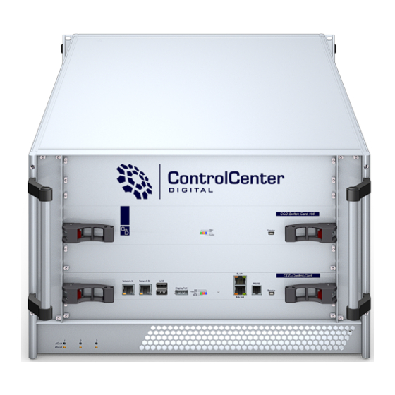
Modularer Aufbau des Matrixswitches Modularer Aufbau des Matrixswitches Dank des modularen Aufbaus des Matrixswitches ControlCenter-Digital-160 können Sie den Matrixswitch durch den Einbau weiterer IO-Karten erweitern oder System- komponenten ersetzen. Übersicht der Komponenten des Matrixswitches Auf der Frontseite sind die Switch-Karte CCD-Switch-Card-160 und die Controller- Karte CCD-Control-Card platziert. - Page 12 3 Monate leichte Staubbelastung: 6 Monate Prüfen Sie regelmäßig den Zustand der Filter. Reinigen Sie leicht verschmutzte Filter durch Ausklopfen und/oder leichte Luftstöße mit Druckluft. Wechseln Sie den Filter spätestens nach einem Zeitraum von 6 Monaten. 8 · G&D ControlCenter-Digital-160...
-
Page 13: Komponenten Ein- Oder Ausbauen
Beachten Sie diesbezüglich folgende Sicherheitshinweise: Blickkontakt mit dem unsichtbaren Laserstrahl vermeiden auf Seite 4 Optische Anschlüsse stets verbinden oder mit Schutzkappen abdecken auf Seite 4 Ausschließlich von G&D zertifizierte Übertragungsmodule verwenden auf Seite 4 G&D ControlCenter-Digital-160 · 9... - Page 14 4. Stellen Sie sicher, dass die Hebel Kontakt zum Gehäuse haben und auf der Höhe der vorgesehenen Löcher der Lochschiene platziert sind. 5. Drücken Sie die Hebel ohne große Kraftanwendung nach innen, um die Karte am Gehäuse zu fixieren. 10 · G&D ControlCenter-Digital-160...
-
Page 15: Lüfter-Boards Ein- Oder Ausbauen
3. Ziehen Sie das Modul aus dem Gehäuse. WICHTIG: Das Spannungsversorgungsmodul hat eine hohe Betriebstemperatur. Vorsicht vor Verbrennungen! So bauen Sie ein Spannungsversorgungsmodul ein: 1. Schieben Sie das Modul in den Schacht. 2. Sobald der Arretierungshebel hörbar einrastet, ist das Modul vollständig eingeschoben. G&D ControlCenter-Digital-160 · 11... -
Page 16: Controller-Karte Ein- Oder Ausbauen
4. Schieben Sie die Karte durch Druck auf die Mitte der Frontblende waagrecht in den Schacht, bis die Hebel Kontakt zum Gehäuse haben. 5. Drücken Sie die Hebel ohne Kraftanwendung nach innen, um die Karte im Gehäuse zu fixieren. 12 · G&D ControlCenter-Digital-160... -
Page 17: Switch-Karte Ein- Oder Ausbauen
Schacht. 4. Stellen Sie sicher, dass die Hebel Kontakt zum Gehäuse haben und auf der Höhe der vorgesehenen Löcher platziert sind. 5. Drücken Sie die Hebel nach innen, um die Karte im Gehäuse zu fixieren. G&D ControlCenter-Digital-160 · 13... -
Page 18: Installation
Fail Fail Dynamic Ports Dynamic Ports Ident. Ident. Portfunction Portfunction Status Status Fail Fail Erforderliches Zubehör Ein bzw. zwei Twisted-Pair-Kabel der Kategorie 5e (oder höher) zum Anschluss des Matrixswitches an ein bzw. zwei lokale Netzwerke. 14 · G&D ControlCenter-Digital-160... -
Page 19: Hinweise Zu Den Kabelwegen
Installation Hinweise zu den Kabelwegen Der modulare Aufbau des Matrixswitches ControlCenter-Digital-160 ermöglicht die einfache Erweiterung, den Austausch und die Wartung der Komponenten. Bedenken Sie beim Verkabeln der Komponenten, dass die Lüfter-Boards in regelmäßi- gen Abständen (s. Seite 7) von Staub und anderen Schmutzpartikeln zu reinigen sind. -
Page 20: Installation Und Anschluss Der Rechnermodule
Verbinden Sie ausschließlich eine Trans.-Schnittstelle des Rechner- moduls mit diesem Matrixswitch! Stromversorgung Power ×: Schließen Sie für jedes eingebaute Spannungsversorgungsmodul ein mitge- liefertes Stromversorgungskabel an. Verbinden Sie das Stromversorgungskabel mit einer Netzsteckdose und schalten Sie den Netzschalter ein. 16 · G&D ControlCenter-Digital-160... -
Page 21: Netzwerkschnittstellen
Das andere Ende des Kabels ist mit einer Netzwerkschnittstelle eines lokalen Netzwerks zu verbinden. Network B: Stecken Sie optional ein als Zubehör erhältliches Twisted-Pair-Kabel der Kategorie 5e (oder höher) ein. Das andere Ende des Kabels ist mit einer Netzwerkschnittstelle eines lokalen Netzwerks zu verbinden. G&D ControlCenter-Digital-160 · 17... -
Page 22: Empfehlungen Zum Twisted-Pair-Kabel
140 Meter AWG24 Installation 5e, 6 oder 7 bis 120 Meter AWG26/27 Patchkabel 5e, 6 oder 7 bis 80 Meter HINWEIS: Die in der obigen Tabelle angegebenen Längen stellen die Summe aller Teilstücke zwischen den Geräten dar. 18 · G&D ControlCenter-Digital-160... - Page 23 80 Meter: Dätwyler uninet® 7702 flex Patchkabel bis 100 Meter: Dätwyler uninet® 5502 AWG24 S-STP Installationskabel mit Steckern bis 140 Meter: Kerpen MegaLine® G12-150 S/F AWG22 Installationskabel mit Buchsen Dätwyler uninet® 7702 AWG 22 Installationskabel mit Buchsen G&D ControlCenter-Digital-160 · 19...
-
Page 24: Erstkonfiguration Der Netzwerkeinstellungen
, um die Anmeldung durchzuführen und das On-Screen-Display (OSD) zu öffnen. 3. Betätigen Sie die -Taste zum Aufruf des Konfigurationsmenüs. 4. Wählen Sie die Zeile Netzwerk und betätigen Sie die Eingabetaste 5. Wählen Sie die Zeile Schnittstellen und betätigen Sie die Eingabetaste 20 · G&D ControlCenter-Digital-160... -
Page 25: Konfiguration Der Globalen Netzwerkeinstellungen
Geben Sie die IP-Adresse des Gateways an. DNS 1: Geben Sie die IP-Adresse des DNS-Servers an. DNS 2: Geben Sie optional die IP-Adresse eines weiteren DNS-Servers an. 6. Betätigen Sie die -Taste zur Speicherung der durchgeführten Änderungen. G&D ControlCenter-Digital-160 · 21... -
Page 26: Verwendung Des Reset-Tasters
3. Halten Sie den Taster weiterhin gedrückt und schalten Sie mindestens ein Spannungsversorgungsmodul des Geräts ein. 4. Sobald die grüne Status-LED leuchtet, lassen Sie die Taste los. HINWEIS: Die Wiederherstellung der Standardeinstellungen ist alternativ auch über die Webapplikation Config Panel möglich. 22 · G&D ControlCenter-Digital-160... -
Page 27: Temporäre Deaktivierung Der Netzfilterregeln
3. Bearbeiten Sie die im Gerät gespeicherten Netzfilterregeln mit der Webapplikation Config Panel und speichern Sie die Regeln anschließend ab. WICHTIG: Wird innerhalb von 15 Minuten keine neue Netzfilterkonfiguration erstellt, werden die ursprünglichen Einstellungen wieder aktiviert. G&D ControlCenter-Digital-160 · 23... -
Page 28: Erweiterung Des Kvm-Matrixsystems
An die können Sie die übergeordneten Matrixswitches anschließen. Die unter- Up-Ports geordneten Matrixswitches einer Kaskade schließen Sie an die Down-Ports WICHTIG: Ausführliche Informationen zur Konfiguration der Dynamic Ports finden Sie im Handbuch der Webapplikation Config Panel. 24 · G&D ControlCenter-Digital-160... -
Page 29: Anschluss Eines Follower-Zentralmoduls
Matrixswitch, an den sie angeschlossen sind) aufgeschaltet werden. Das System übernimmt das (bidirektionale) Routing der KVM-Signale und wählt hierbei den jeweils optimalen Signalpfad zwischen den Modulen. Weitere Informationen zum finden Sie im separaten Handbuch der KVM Matrix-Grid™ Webapplikation. G&D ControlCenter-Digital-160 · 25... -
Page 30: Erweiterung Der Schaltbaren Signale
Durch die Zuordnung mehrerer Kanäle zu einem Arbeitsplatz oder einem Rechner erstellen Sie eine sogenannte Kanal-Gruppierung. HINWEIS: Arbeitsplatz- bzw. Rechnermodule, die Sie als Zusatzkanal einer Kanal-Gruppierung zugeordnet haben, werden im OSD nicht aufgeführt. Ausführliche Informationen zur Kanal-Gruppierung finden Sie im Handbuch der Webapplikation. 26 · G&D ControlCenter-Digital-160... -
Page 31: Statusanzeigen
LED zur Identifizierung des Gerätes wurde eingeschaltet. LED zur Identifizierung des Gerätes aktiviert. Network A gelb flackert Netzwerkaktivität findet statt. keine Netzwerkaktivität grün Netzwerkverbindung hergestellt. Keine Netzwerkverbindung Network B gelb flackert Netzwerkaktivität findet statt. keine Netzwerkaktivität grün Netzwerkverbindung hergestellt. Keine Netzwerkverbindung G&D ControlCenter-Digital-160 · 27... - Page 32 In der Webapplikation wird dieser Modus als DOWN- Modus bezeichnet. flackert Tastatur- und Mauseingaben werden vom aufge- schalteten Arbeitsplatzmodul übertragen. Der Rhythmus des Flackerns wird durch die Eingaben des Anwenders bestimmt. Es konnte keine Verbindung zum Arbeitsplatz- bzw. Rechnermodul hergestellt werden. 28 · G&D ControlCenter-Digital-160...
- Page 33 Das Spannungsersorgungsmodul wird mit der erforderlichen Eingangs- spannung versorgt. grün Der Matrixswitch wird mit der erforderlichen Spannung durch das Spannungsversorgungsmodul versorgt. Die Ausgangsspannung ist fehlerhaft. Der Matrixswitch wird nicht mit der Spannung dieses Spannungsver- sorgungsmoduls versorgt. G&D ControlCenter-Digital-160 · 29...
-
Page 34: Technische Daten
+5 bis +45 °C Luftfeuchte: 20 % bis 80 %, nicht kondensierend Lagerumgebung Temperatur: -20 °C bis +55 °C Luftfeuchte: 15 % bis 85 %, nicht kondensierend Konformität CE, UKCA, FCC Klasse A, TAA, EAC, RoHS, WEEE, REACH 30 · G&D ControlCenter-Digital-160... - Page 36 © Guntermann & Drunck GmbH 2023. All rights reserved. Version 1.70 – 15/12/2023 Firmware: 2.6.000 Guntermann & Drunck GmbH Obere Leimbach 9 57074 Siegen Germany Phone +49 271 23872-0 +49 271 23872-120 www.gdsys.com sales@gdsys.com i · G&D ControlCenter-Digital-160...
- Page 37 Operation of this equipment in a residential area is likely to cause harmful inter- ference in which case the user will be required to correct the interference at his own expense. G&D ControlCenter-Digital-160 · ii...
- Page 38 Configuration and highlighting of port assignment ........24 Connecting a follower central module ............25 KVM Matrix-Grid™ (subject to a charge) ............25 Expanding switchable signals ................. 26 Status displays ....................27 Technical data ....................30 iii · G&D ControlCenter-Digital-160...
-
Page 39: Safety Instructions
When installing the devices, ensure that the devices’ mains plugs remain accessible at all time. Do not cover the ventilation openings For device variants with ventilation openings, it must always be ensured that the ventilation openings are not covered. G&D ControlCenter-Digital-160 · 1... - Page 40 Failure to observe this precautionary measure can result in injuries and damage to the device. Operate the device exclusively in the intended field of application The devices are designed for indoor use. Avoid extreme cold, heat or humidity. 2 · G&D ControlCenter-Digital-160...
- Page 41 VORSICHT: Es besteht Explosionsgefahr, wenn die Batterie durch einen falschen Batterie-Typ ersetzt wird. Entsorgen Sie gebrauchte Batterien umweltgerecht. Gebrauchte Batterien dürfen nicht in den Hausmüll geworfen werden. Beachten Sie die gültigen Vorschriften zur Entsorgung elektronischer Produkte. G&D ControlCenter-Digital-160 · 3...
- Page 42 Safety instructions Special advices for dealing with laser technology The fiber variants of the ControlCenter-Digital-160 series use components with laser technology which comply with laser class 1 or better. They meet the requirements according to EN 60825-1:2014 as well as U.S.
-
Page 43: Matrix Switch "Controlcenter-Digital
A KVM matrix system consists of at least one central module, one console module and one computer module. The matrix switch ControlCenter-Digital-160 is the central part of a KVM matrix system. Both, computer and console modules, are connected to the central module. -
Page 44: Expanding A Kvm Matrix System
Information about these technologies is given in the separate manual of the webappli- cation. Package contents 1 × matrix switch ControlCenter-Digital-160 3 × power cable (PowerCable-2 Standard) 2 × mounting bar incl. mounting material 1 × blanking panel for IO slot (CCD-IO-16-Card-Cover) ... -
Page 45: Modular Design Of The Matrix Switch
The cards have the following tasks: The contains the central switching logic of the matrix switch. switch card (1) The controller card (2) manages, monitors and controls all functions of the matrix switch. G&D ControlCenter-Digital-160 · 7... - Page 46 Light exposure to dust: 6 months Check the filter condition regularly. Tap the filter or use light blows of compres- sed air to clean the filter. Change the filter at the latest after six months. 8 · G&D ControlCenter-Digital-160...
-
Page 47: Installing Or Replacing Components
Mind the following instructions when dealing with laser beams: Avoid direct eye exposure to beam on page 4 Always connect optical connections or cover them with protection caps on page 4 Only use G&D certified transmission modules on page 4 G&D ControlCenter-Digital-160 · 9... - Page 48 4. Make sure that the levers are connected to the housing and are placed at the height of the holes of the perforated rail. 5. Push the levers inwards without using much force and fix the card in the housing. 10 · G&D ControlCenter-Digital-160...
-
Page 49: Installing Or Replacing Fan Boards
The power supply module has a high operational temperature. Beware of burnings! How to install a power supply module: 1. Slide the module into the slot. 2. Once the locking lever clicks, the module is completely inserted. G&D ControlCenter-Digital-160 · 11... -
Page 50: Installing Or Replacing The Controller Card
4. Press the middle of the front panel to slide the card horizontally in the slot until the levers are connected to the housing. 5. Push the levers inwards without using much force and fix the card in the housing. 12 · G&D ControlCenter-Digital-160... -
Page 51: Installing Or Replacing The Switch Card
4. Make sure that the levers are connected to the housing and are placed at the height of the holes of the perforated rail. 5. Push the levers inwards to fix the card in the housing. G&D ControlCenter-Digital-160 · 13... -
Page 52: Installation
Dynamic Ports Dynamic Ports Ident. Ident. Portfunction Portfunction Status Status Fail Fail Required accessories One or two category 5e (or better) twisted pair cables to connect the matrix switch to one or two local networks. 14 · G&D ControlCenter-Digital-160... -
Page 53: Instructions On Cable Runs
Installation Instructions on cable runs The modular design of the matrix switch ControlCenter-Digital-160 makes it easy to expand, replace or maintain its components. When connecting the components, remember that the fan boards must be cleaned on a regular basis (see page 7). Therefore, the boards must not be covered by cables. -
Page 54: Installing And Connecting Computer Modules
Trans. interfaces to this matrix switch! Power supply Connect one of the supplied power cables for each installed power supply Power ×: module. Connect the power cable with a power socket and turn on the power switch. 16 · G&D ControlCenter-Digital-160... -
Page 55: Network Interfaces
Connect the other end of the cable to a network interface of the local network. Network B: Plug in a category 5e (or better) twisted-pair cable, which is available as accessory. Connect the other end of the cable to a network interface of the local network. G&D ControlCenter-Digital-160 · 17... -
Page 56: Recommended Twisted Pair Cables
5e, 6 or 7 Up to 120 m AWG26/27 Patch cable 5e, 6 or 7 Up to 80 m NOTE: The lengths mentioned in the table above must be interpreted as the sum of all segments between the devices. 18 · G&D ControlCenter-Digital-160... - Page 57 Patch cable Up to 100 meters: Dätwyler uninet® 5502 AWG24 S-STP Installation cable with sockets Up to 140 meters: Kerpen MegaLine® G12-150 S/F AWG22 Installation cable with sockets Dätwyler uninet® 7702 AWG 22 Installation cable with sockets G&D ControlCenter-Digital-160 · 19...
-
Page 58: Initial Configuration Of Network Settings
The default admin password for devices manufactured before October 2020 is 4658 2. Press Enter to log in and open the on-screen display (OSD). 3. Press to call the Configuration menu. 4. Select Network and press Enter 5. Select Interfaces and press Enter 20 · G&D ControlCenter-Digital-160... -
Page 59: Configuring Global Network Settings
Enter the domain the matrix switch is to belong to. Gateway: Enter the gateway IP address. DNS 1: Enter the DNS server IP address. DNS 2: Enter the IP address of another DNS server (option). 6. Press to save your settings. G&D ControlCenter-Digital-160 · 21... -
Page 60: Reset Button
3. Keep the button pressed and turn on at least one of the device’s power supply modules. 4. Release the button when the green Switch-LED starts blinking. NOTE: You can also use the Config Panel web application to reset the default settings. 22 · G&D ControlCenter-Digital-160... -
Page 61: Temporarily Disabling The Netfilter Rules
3. Use the Config Panel web application to edit the netfilter rules that are stored in the appliance and save these rules. IMPORTANT: The former settings are reactivated if you do not create any new netfilter rules within 15 minutes. G&D ControlCenter-Digital-160 · 23... -
Page 62: Expanding The Kvm Matrix System By Cascading
Connect leader matrix switches to and follower matrix switches of a cascade to up ports ports. down IMPORTANT: Detailed information about the configuration of dynamic ports is given in the manual of the web application Config Panel. 24 · G&D ControlCenter-Digital-160... -
Page 63: Connecting A Follower Central Module
The system takes over the (bidirectional) routing of KVM signals and chooses the ideal signal path between modules. More information about the KVM Matrix-Grid™ are given in the separate manual of the web application. G&D ControlCenter-Digital-160 · 25... -
Page 64: Expanding Switchable Signals
Assigning multiple channels to a console or computer creates a channel group. NOTE: The OSD does not show any console or computer modules that you added as additional channels to the channel group. Detailed information on channel grouping can be retrieved in the web application manual. 26 · G&D ControlCenter-Digital-160... -
Page 65: Status Displays
LED to identify device is active. Network A Yellow Flicker- Network activity No network activity Green Network connection established No network connection Network B Yellow Flicker- Network activity No network activity Green Network connection established No network connection G&D ControlCenter-Digital-160 · 27... - Page 66 In the web application, this mode is called DOWN mode. Flickering Keyboard and mouse inputs are transmitted by the accessing console module. The rhythm of the flickering is defined by the user’s inputs. No connection to console module or computer module. 28 · G&D ControlCenter-Digital-160...
- Page 67 The power supply module is supplied with the required input voltage. Green The power supply module supplies the required voltage to the matrix switch. Incorrect output voltage. The power supply module does not supply voltage to the matrix switch. G&D ControlCenter-Digital-160 · 29...
-
Page 68: Technical Data
Air humidity: 20 % to 80 %, non-condensing Storage Temperature: -20 °C to +55 °C environment Air humidity: 15 % to 85 %, non-condensing Conformity CE, UKCA, FCC class A, TAA, EAC, RoHS, WEEE, REACH 30 · G&D ControlCenter-Digital-160... - Page 72 G&D. AND KVM FEELS RIGHT. Hauptsitz | Headquarter US-Büro | US-Office Guntermann & Drunck GmbH Systementwicklung G&D North America Inc. Obere Leimbach 9 | D-57074 Siegen | Phone +49 271 23872-0 4001 W. Alemada Avenue | Suite 100, Burbank, CA 91505 | Phone +1-818-748-3383 sales.us@gdsys.com | www.gdsys.com sales@gdsys.com | www.gdsys.com...
Need help?
Do you have a question about the ControlCenter-Digital-160 and is the answer not in the manual?
Questions and answers