Table of Contents
Advertisement
Quick Links
D-Series - Field mounted indicators for safe and hazardous areas.
F-Series - Field mounted indicators for safe and hazardous areas. More info: www.fluidwell.com/fseries
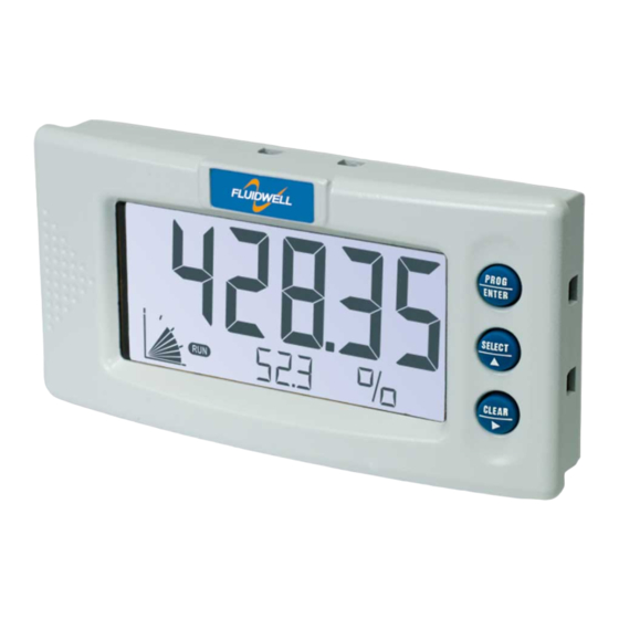
D490-A-PL
LOOP POWERED INDICATOR
Signal input sensor: 4-20mA.
Options: Backlight and Intrinsic Safety
More info: www.fluidwell.com/dseries
Advertisement
Table of Contents

Related Manuals for Fluidwell D490-A-PL


Summary of Contents for Fluidwell D490-A-PL
- Page 1 D490-A-PL LOOP POWERED INDICATOR Signal input sensor: 4-20mA. Options: Backlight and Intrinsic Safety D-Series - Field mounted indicators for safe and hazardous areas. F-Series - Field mounted indicators for safe and hazardous areas. More info: www.fluidwell.com/fseries More info: www.fluidwell.com/dseries...
-
Page 2: Safety Instructions
▪ Any responsibility is lapsed if the instructions and procedures as described in this manual are not followed. ▪ LIFE SUPPORT APPLICATIONS: The D490-A-PL is not designed for use in life support appliances, devices, or systems where malfunction of the product can reasonably be expected to result in a personal injury. -
Page 3: About The Operation Manual
This operation manual describes the standard unit as well as most of the options available. For additional information, please contact your supplier. A hazardous situation may occur if the D490-A-PL is not used for the purpose it was designed for or is used incorrectly. Please carefully note the information in this operating manual indicated by the pictograms: A "warning"... -
Page 4: Table Of Contents
Disposal ..............................2 Safety rules and precautionary measures .................... 2 About the operation manual ......................... 3 Contents manual ........................... 4 Introduction ........................... 5 1.1. System description of the D490-A-PL ................. 5 2.1. General ........................6 2.2. Control panel ....................... 6 2.3. -
Page 5: Introduction
This user manual describes model D490-A-PL with an analog 4-20mA input type "-A version". One active 4-20mA current loop can be connected to the D490-A-PL. The D490-A-PL is powered from the loop (sensor signal) and does not require any additional external power supply. -
Page 6: General
All instructions in this manual are to be observed. ▪ Take careful notice of the " Safety rules, instructions and precautionary measures " in the front of this manual. This chapter describes the daily use of the D490-A-PL. This instruction is meant for users / operators. 2.2. -
Page 7: Operator Information And Functions
For the Operator, the following functions are available (if activated): ▪ Display value and measuring unit This is the main display information of the D490-A-PL. After selecting any other information, it will always return to this main display automatically. ▪... -
Page 8: Configuration
3.2. PROGRAMMING SETUP-LEVEL 3.2.1. ENTERING SETUP-LEVEL Configuration of the D490-A-PL is done at SETUP-level, which can be reached at all times while the D490-A-PL remains fully operational. At SETUP-level the display will deactivate the indicator and activate the SETUP indicator. -
Page 9: Programming Sequence
Page 9 Use the control panel to navigate through SETUP-level PROG-key When a function is selected, this key is used to start the programming sequence. SELECT-key This key is used to select the next function in the list (e.g. 1 → 1.1 → 1.2 → 1). When the top of the list is reached, it will wrap around and return to the function group selection. -
Page 10: Returning To Operator-Level
Page 10 Step 3: Finishing the programming sequence PROG-key During the programming sequence, this key is used to confirm the new value and return to SETUP-level. To cancel the operation, either press the PROG-key for 3 seconds or wait for 20 seconds: the programming sequence is cancelled and the former value is reinstated. -
Page 11: Explanation Of Setup-Menu 1: Display
Page 11 3.2.6. EXPLANATION OF SETUP-MENU 1: DISPLAY 1 - DISPLAY SETUP – 1.1 determines the measurement unit to be displayed. UNIT The following units can be selected: L – NL – mL – M3 – AM3 – NM3 – mg – g – Kg – TON – OZ – GAL – USGAL –... -
Page 12: Explanation Of Setup-Menu 2: Sensor
Page 12 3.2.7. EXPLANATION OF SETUP-MENU 2: SENSOR 2 - SENSOR FORMULA The D490-A-PL can process the 4-20mA signal in two ways: ▪ Interpolation: the signal is processed linear V = S x I ▪ Square root: for differential pressure √... -
Page 13: Explanation Of Setup-Menu 3: Others
3 - OTHERS TYPE OF MODEL For support and maintenance it is important to have information about the characteristics of the D490-A-PL. VERSION SOFTWARE Your supplier will ask for this information in the case of a serious breakdown or to assess the suitability of your model for upgrade considerations. -
Page 14: Installation
Operating Manual before carrying out its instructions. ▪ The D490-A-PL may only be operated by personnel who are authorised and trained by the operator of the facility. All instructions in this manual are to be observed. -
Page 15: Mechanical Installation
Page 15 4.3. MECHANICAL INSTALLATION Panel cut out Maximum panel thickness: 6mm (1/4") Fig. 5: Dimensions panel-mount enclosure. FW-D490-A-PL_v0503_01_EN.docx... -
Page 16: Electrical Installation
For easy installation, the signal link between terminals 2 and 3 can be used to interconnect the signal shields of two separate cables. Terminal 4-5; Power supply - Type PL The D490-A-PL-XI will be powered from the 4-20mA input signal. FW-D490-A-PL_v0503_01_EN.docx... - Page 17 Terminal 4-5; 4-20mA signal input The D490-A-PL requires a 4-20mA signal that will be processed 4 times. The input is not isolated. With the use of the signal links between terminal 2 and 3 and between terminal 6 and 7, it is possible to easily connect the signal wires and cable screens of two separate cables.
-
Page 18: Intrinsically Safe Applications
Page 18 INTRINSICALLY SAFE APPLICATIONS 5.1. GENERAL INFORMATION AND INSTRUCTIONS ▪ Mounting, electrical installation, start-up and maintenance of this device may only be carried out by trained personnel authorized by the operator of the facility. Personnel must read and understand this Operating Manual before carrying out its instructions. ▪... -
Page 19: Intrinsically Safe Installation Under Atex / Iecex Scheme
Page 19 5.2. INTRINSICALLY SAFE INSTALLATION UNDER ATEX / IECEX SCHEME For Intrinsically Safe installations under ATEX and IECEx Scheme, the following safety parameters apply: Input circuit (terminals 4 and 5): Backlight circuit (terminals 9 and 10): = 0.96 The backlight circuit is separated from the input circuit. Ambient temperature: -30 °C ... -
Page 20: Intrinsically Safe Installation Under Csa
Page 20 5.3. INTRINSICALLY SAFE INSTALLATION UNDER CSA For Intrinsically Safe installations under CSA certification, the following safety parameters apply: Control drawing: See control drawing CD1104.11 on the next page. Ambient temperature: -30 °C ... +70 °C / -22 °F … +158 °F Range = FW-D490-A-PL_v0503_01_EN.docx... - Page 21 Page 21 Fig. 9: CSA Control Drawing CD1104.11 FW-D490-A-PL_v0503_01_EN.docx...
-
Page 22: Product Marking
Page 22 5.4. PRODUCT MARKING Serial number and year of production This information can be looked-up on the display setup function (par. 3.2.2.) and on the outside label. YEAR WEEK NUMBER Label information Intrinsically Safe: Label rear side label panel-mount enclosures: Fig. -
Page 23: Maintenance
Repairs should only be carried out by the manufacturer or his authorized agent. 6.3. REPAIR POLICY If you have any problem with your Fluidwell product and you wish to repair it, please follow the procedure below: a. Obtain a Return Material Authorization (RMA) from your supplier or distributor Together with the RMA, you need to complete a repair form to submit detailed information about the problem. -
Page 24: Appendix A: Technical Specification
Page 24 APPENDIX A: TECHNICAL SPECIFICATION GENERAL Display Type High intensity reflective numeric and alphanumeric LCD, UV-resistant. 90x40mm (3.5”x1.6”) Digits 5 ½ 26mm (1") and eleven 8mm (0.31"). Various symbols and measuring units. Piegraph 10 segment range indication in relation to its measuring range 0-100% Refresh rate 1 times/sec. - Page 25 Page 25 INPUTS Sensor Type A 4-20mA - with signal calibration feature. Accuracy Resolution: 14 bit, < 0.01mA / ±0.05% FS. Low level cut-off programmable. Span 0.00001 to 199,999 units with variable decimal position. Offset -99,999 to +199,999 units Update time Four times a second. Voltage drop <1 V DC Relationship Linear and square root calculation.
-
Page 26: Appendix B: Problem Solving
Page 26 APPENDIX B: PROBLEM SOLVING In this appendix, several problems are included that can occur when the D490-A-PL is going to be installed or while it is in operation. Display is "0 / zero" while a higher signal is available: Check: ▪... -
Page 27: Appendix C: Declaration Of Conformity
Page 27 APPENDIX C: DECLARATION OF CONFORMITY FW-D490-A-PL_v0503_01_EN.docx... -
Page 28: Index Of This Manual
Fig. 4: SETUP matrix structure ......................8 Fig. 5: Dimensions panel-mount enclosure..................15 Fig. 6: Overview of terminal connectors standard configuration D490-A-PL........16 Fig. 7: Overview terminal connection 4-20mA input................17 Fig. 8: Terminal connections ATEX and IECEx .................. 19 Fig. -
Page 29: Notes
Page 29 NOTES FW-D490-A-PL_v0503_01_EN.docx... -
Page 30: Notes
Page 30 NOTES FW-D490-A-PL_v0503_01_EN.docx... -
Page 31: List Of Configuration Settings
Page 31 LIST OF CONFIGURATION SETTINGS LIST OF CONFIGURATION SETTINGS SETTING DEFAULT DATE: DATE: 1 - DISPLAY Enter your settings here 1.1 unit 1.2 time unit No unit 1.3 decimals 00000 1.4 offset 0 uS 1.5 span 1600 uS 1.6 direction Normal 1.7 current 1.8 percentage... - Page 32 Page 32 Fluidwell bv FW-D490-A-PL_v0503_01_EN.docx PO box 6 Voltaweg 23 Website: www.fluidwell.com 5460 AA Veghel 5466 AZ Veghel Find your nearest representative: www.fluidwell.com/representatives The Netherlands The Netherlands Copyright Fluidwell bv - © 2020- FW-D490-A-PL_v0503_02_EN.docx...
Need help?
Do you have a question about the D490-A-PL and is the answer not in the manual?
Questions and answers