
Related Manuals for Fluidwell D Series


Summary of Contents for Fluidwell D Series
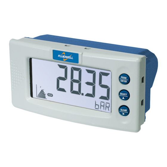
- Page 1 D090-A OWERED NDICATOR Signal input sensor: (0)4-20mA Fluidwell D-Series Indicators - The better alternative for DIN panel mount indicators...
- Page 2 User manual D090-A Loop Powered Indicator Health and Safety Information Caution: The D090-A must only be installed, operated and maintained by competent personnel that received proper training on regular basis, including instructions on the various types of protection and installation practices, relevant rules and regulations, and the general principles of area classification.
-
Page 3: About Functions And Type Codes
Customers using or selling the D090-A or related products for use in such applications do so at their own risk and agree to fully indemnify Fluidwell bv and supplier for any damages resulting from such improper use or sale. -
Page 4: Prerequisites
User manual D090-A Loop Powered Indicator This guide consists of the following main sections: chapter 1: "Introduction" on page 1 Provides an introduction and technical overview of the D090-A Loop Powered Indicator. chapter 3: "Installation Instructions" on page 7 Provides mechanical and electrical installation instructions. -
Page 5: Table Of Contents
Contents About this guide ............iii About functions and type codes . - Page 6 Contents Operator alarms ............22 Range error .
-
Page 7: Introduction
Introduction CHAPTER System Description of the D090-A Functions and Features The Loop Powered Indicator model D090-A is a microprocessor controlled device to display the actual flowrate. The D090-A has been designed with a focus on: • Ultra-low power consumption, to allow for battery operation of up to five years. •... -
Page 8: The D090-A Display Functions
User manual D090-A Loop Powered Indicator 1 – I NTRODUCTION The D090-A Display Functions The D090-A has a very large transflective LCD with a number of symbols and digits to display measuring units, status information, trend indication and keyword messages. Figure 2: The display functions of the D090-A D090-A status indicators Numerical 26mm (1”) -
Page 9: Available D090-A Configurations
User manual D090-A Loop Powered Indicator – 1 NTRODUCTION Available D090-A configurations Your D090-A model is available in a number of hardwired configuration options. A product label on the back side of the unit identifies which configuration options are included in your D090-A. - Page 10 User manual D090-A Loop Powered Indicator 1 – I NTRODUCTION This page is left blank intentionally. FW-D090-A-MAN-EN_v0101_02...
-
Page 11: Specifications Of The D090-A
Specifications of the D090-A CHAPTER General specifications Display Type High intensity reflective numeric and alphanumeric LCD, UV- resistant. Digits 5½ very large 26mm (1”) digits. Various symbols and measuring units. Refresh rate User definable: 8 times/sec - 30 secs - 1 time/30 secs - off. Type ZB Transflective LCD with bi-color LED backlight;... -
Page 12: Terminal Connections
User manual D090-A Loop Powered Indicator 2 – S D090-A PECIFICATIONS OF THE Terminal connections Type Removable plug-in terminal strip. Wire max. 1.5mm and 2.5mm solid / stranded. Screw thread Tightening torque 0.5-0.6 Nm Data protection Memory type EEPROM; data retention >10 years Automatic backup of settings upon change &... -
Page 13: Installation Instructions
Installation Instructions CHAPTER Note: This section describes various hardware configurations of the D090-A. Your particular model of the D090-A may not support all configuration options described. Mechanical Installation Figure 1: Mechanical mounting precautions To extend life of your unit: • Mount the D090-A on a solid base to avoid vibrations. •... -
Page 14: Electrical Installation - General
User manual D090-A Loop Powered Indicator 3 – I NSTALLATION NSTRUCTIONS Electrical installation – general Overview of Terminal Connectors To gain access to the connectors open the panel containing the D090-A. You now see the battery cover with the battery and the connectors at the back side of the display unit as shown below. The actual number and size of connectors depends on your particular model. - Page 15 User manual D090-A Loop Powered Indicator – 3 NSTALLATION NSTRUCTIONS Figure 5: Voltage switch positions 8.2V Connector Types and Wiring Sizes The following connector types are fitted. Wires are connected using a flat head screw driver: Classic COMBICON A screw connector with 5.08mm pitch, suitable for 0.2—2.5mm2 or AWG 24—12 wire.
-
Page 16: Configuring The D090-A
Configuring the D090-A CHAPTER General The D090-A has three buttons and four modes of operation, one of which is “off”. The active modes are displayed by status indicators. Configuration of the D090-A is possible via the Setup and Program modes, which are indicated by PROGRAM SETUP Warning:... -
Page 17: Quick Reference Menu
User manual D090-A Loop Powered Indicator D090-A – 4 ONFIGURING THE Quick Reference Menu Shelf mode Mode to deactivate the unit for storage. The unit is switched off. Press twice to switch the unit on and perform a self SELECT test. -
Page 18: Modes Of Operation
User manual D090-A Loop Powered Indicator 4 – C D090-A ONFIGURING THE Modes of Operation Shelf Mode In Shelf mode the D090-A shuts down and can be shelved, stored or transported without draining the battery. All settings in EEPROM remain stored, even when the battery is removed. To wake the unit up press the center button ( /) twice to bring it in Operator mode. - Page 19 User manual D090-A Loop Powered Indicator D090-A – 4 ONFIGURING THE Program Mode In Program mode you can change the properties (value or setting) of a selected Function item. Warning: Not understanding the effect of your changes can cause unexpected system responses, resulting in process inefficiency, product spilling and downtime.
-
Page 20: Overview Of Setup Functions And Settings
User manual D090-A Loop Powered Indicator 4 – C D090-A ONFIGURING THE Overview of Setup Functions and Settings & ETUP FUNCTION SETTINGS DEFAULT VALUE 1 – D ISPLAY 11 Unit L - L- L - M3 - M3 - SGAL IGAL - °C - °F - °K - % - INCH... -
Page 21: The D090-A Setup Functions Explained
User manual D090-A Loop Powered Indicator D090-A – 4 ONFIGURING THE The D090-A Setup Functions Explained Warning: Disconnect the D090-A from the process before modifying setup items: Changes to setup items take immediate effect! 1 — D ETUP ISPLAY Below setup options define the display functions for the operator. SETUP Unit Unit determines the measurement unit for flowrate. - Page 22 User manual D090-A Loop Powered Indicator 4 – C D090-A ONFIGURING THE SETUP Direction If the display is required to increase in value as the input current increases, select the scale direction "normal". Alternatively, select "reverse" if the display is required to decrease as the input current rises. reverse –...
- Page 23 User manual D090-A Loop Powered Indicator D090-A – 4 ONFIGURING THE 3 — S ETUP ENSOR Below setup items adjust the D090-A to accomodate to your type of flowmeter signal. SETUP Formula Depending on the type of flowmeter, the flowmeter signal from the field is either linear to the actual flowrate, or a square of the actual flowrate.
- Page 24 User manual D090-A Loop Powered Indicator 4 – C D090-A ONFIGURING THE SETUP Filter Filter is used to filter undesired oscillation and jitter from the analog input signal, caused by rapid changes in Pulse. Note: A filter allows for a more stable but less detailed flowrate readout. The higher the filter level, the better it will filter out disturbances.
- Page 25 User manual D090-A Loop Powered Indicator D090-A – 4 ONFIGURING THE SETUP Calibrate Low / 4mA Calibrate Low / 4mA allows you to tune the analog input value that represents minimum flowrate. Warning: Do not tune while the D090-A is processing data! •...
- Page 26 User manual D090-A Loop Powered Indicator 4 – C D090-A ONFIGURING THE 4 — O ETUP THERS Below setup items identify the characteristics, location and accessibility of your D090-A. Below information may be requested when you call for support or maintenance –e.g. in the case of a serious breakdown–...
-
Page 27: Operating The D090-A
Operating the D090-A CHAPTER The D090-A default mode of operation is the Operator mode. In Operator mode field information is processed and displayed. What information is displayed how depends on the configuration settings, as described in "Configuring the D053-A" on page 15 Signals, generated by the flowmeter in the field, are processed real time in the background, independent from the configured display update speed. -
Page 28: Operator Functions
User manual D090-A Loop Powered Indicator 5 – O D090-A PERATING THE Operator functions For the operator the following functions are available: Display flowrate • This is the main display information of the D090-A. After selecting any other information, it will always return to this main display automatically. -
Page 29: Maintenance
Failure to do so may result in a potentionally hazardous situation. Caution: Caution: Warranty and certification of the D090-A are waived when repairs are carried out by others than Fluidwell bv or his authorized repair centre. FW-D090-A-MAN-EN_v0101_02... -
Page 30: Setup Function Configuration Examples
Setup function configuration APPENDIX examples This appendix provides information and examples that might help you configure a number of setup functions. Calculating the Span Calculating the span for flowrate Below examples show ways to calculate the span and corresponding decimals. Example: Calculating the span for flowrate (1) Let us assume that the flowmeter generates 20mA at a rate of 652.31 USGAL per hour, the selected unit is barrels per day (see... -
Page 31: Setting Up An Analog Fillter
User manual D090-A Loop Powered Indicator – A ETUP FUNCTION CONFIGURATION EXAMPLES 4 The display shows either Default or Cal Set. Press to activate the calibration menu and PROG to select Calib (calibrate). 5 With Calib displayed, press again to execute the calibration. PROG When Cal Set is displayed, calibration is completed. - Page 32 User manual D090-A Loop Powered Indicator A – S ETUP FUNCTION CONFIGURATION EXAMPLES To determine what filter value works best for your application, execute the steps below: Caution: Define your filter value carefully. If the filter value is chosen too high the D090-A may not –or too slowly, respond to changes in flowrate.
-
Page 33: Troubleshooting The D090-A
Troubleshooting the D090-A APPENDIX In this appendix several issues are described that may occur during installation or operation of your D090-A. If you have an issue that is not reported here, please contact your supplier. Flowrate displays “0 / zero” while there is flow Check: •... - Page 34 User manual D090-A Loop Powered Indicator B – T D090-A ROUBLESHOOTING THE This page is left blank intentionally. FW-D090-A-MAN-EN_v0101_02...
- Page 35 User manual D090-A Loop Powered Indicator FW-D090-A-MAN-EN_v0101_02...
- Page 36 44 Password 0000 45 Tag Number 0000000 Fluidwell bv P.O. Box 6 Voltaweg 23 T +31 (0)413 343 786 5460 AA Veghel 5466 AZ F +31 (0)413 363 443 Copyright Fluidwell bv - 2015 The Netherlands The Netherlands E displays@fluidwell.com FW-D090-A-MAN-EN_v0101_02...
Need help?
Do you have a question about the D Series and is the answer not in the manual?
Questions and answers