Table of Contents
Advertisement
Quick Links
Advertisement
Table of Contents

Related Manuals for Fluidwell D Series


Summary of Contents for Fluidwell D Series
- Page 1 User Manual D014-A FLOW RATE INDICATOR / TOTALIZER WITH SCALED PULSE OUTPUT Signal input: (0)4-20 mA flowmeter signal Signal output: one scaled pulse reflecting total Options: backlight D-Series - Panel mounted indicators More info: www.fluidwell.com/dseries...
-
Page 2: Table Of Contents
User Manual D014-A TABLE OF CONTENTS ABOUT THIS MANUAL......................How to use this manual ....................Use of pictograms ......................Warranty and technical support ..................Model Reference ......................SAFETY ............................ Personal safety ....................... End-user responsibilities....................Potential equipment damage ..................Disposal of electronic waste ................... INTRODUCTION........................ - Page 3 D014-A User Manual MAINTENANCE........................28 General directions......................28 Instructions for repair ...................... 28 Battery replacement......................29 7.3.1 Safety instructions ......................29 7.3.2 Battery replacement procedure ..................29 7.3.3 Disposal of batteries ....................... 30 APPENDIX A - TECHNICAL SPECIFICATION ................31 General ...........................
-
Page 4: About This Manual
● incorrect functioning of the unit or connected instruments. A note informs you of important information. WARRANTY AND TECHNICAL SUPPORT For warranty and technical support on your Fluidwell products, visit our internet site www.fluidwell.com or contact us at support@fluidwell.com. MODEL REFERENCE Hardware version: 03.04.xx... -
Page 5: Safety
D014-A User Manual SAFETY PERSONAL SAFETY ● Risk of electric shock: Only open the unit if all leads are free of potential electrical energy. ● Immediately inform the person responsible for the installation if you disagree with the safety precautions or if you detect errors or danger. END-USER RESPONSIBILITIES ●... -
Page 6: Introduction
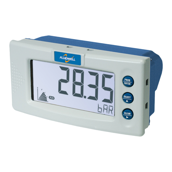
User Manual D014-A INTRODUCTION SYSTEM DESCRIPTION The flow rate indicator / totalizer model D014-A is a microprocessor-driven instrument designed to show the current flow rate, resettable total and non-resettable accumulated total, as well as to generate a scaled pulse according to the accumulated total. Fig. 1: The D014 This manual describes the daily use, configuration and installation of the D014-A with analog... -
Page 7: Installation Example
D014-A User Manual Input ● One flowmeter with a passive or active (0)4-20mA analog signal output ● Several options are available for powering the sensor. Output ● A scalable pulse output is available from the D014-A, reflecting the passing of a programmable quantity. -
Page 8: Operation
User Manual D014-A OPERATION This unit may only be operated by authorized and trained personnel who have read and understood this manual, particularly Section 2: Safety [»5] INTRODUCTION This chapter describes the daily use and operation of the D014-A. For this, the D-Series is equipped with a control panel that provides the operator with various functions, information and operating modes. -
Page 9: Backlight (Type Zb)
D014-A User Manual Normally, the display is updated depending on the refresh rate selected in the configuration settings. By pressing any key, the display switches to refreshing the information 8 times per second. After 30 seconds of key inactivity, the display returns to the configured refresh rate. TOTAL RATE Fig. 4:... -
Page 10: Internal Error
User Manual D014-A Fig. 5: Example of low battery alarm 4.4.3 INTERNAL ERROR When an internal error occurs, “ALARM” will be displayed. Press the SELECT key several times to display the 4-digit error code. Consult for more information. Section B: Troubleshooting [»33] Page 10 FW_D014-A_M_v0501-01_EN... -
Page 11: Configuration
D014-A User Manual CONFIGURATION INTRODUCTION This chapter describes how technicians can use configuration settings to configure the D-Series for optimal functionality. Configuration of the D014-A can be done in SETUP mode, using the front keys. CONFIGURING USING SETUP MODE For an overview of Operating modes, see Section 4.1.1: Operating modes [»8] Changing settings may influence current operation In SETUP mode the unit remains fully operational. -
Page 12: Changing Configuration Settings
User Manual D014-A 5.2.3 CHANGING CONFIGURATION SETTINGS A menu item either contains a value (a number with optionally a decimal point and sign, e.g. -123.45) or a selection list (e.g. L – m - USGAL). After a menu item is selected in the SETUP menu, a new value can be programmed by performing the following steps. -
Page 13: Setup Menu Overview
D014-A User Manual SETUP MENU OVERVIEW TOTAL DEFAULT UNIT L - m3 - kg - lb - GAL - USGAL - bbl - no unit DECIMALS 0 - 3 0.0010 - 999,999 1600 SPAN DECIMALS SPAN 0 - 6 FLOW RATE DEFAULT UNIT mL - L - m3 - mg - g - kg - ton - GAL - bbl - lb - cf - REV -... -
Page 14: Menu 2: Flow Rate
User Manual D014-A ● The rate per second is 2,481.3 / 60 = 41.355 L/sec, which equals 0.041355 m /sec. Thus, the span is 0.041355. ● Enter the Span as 041355 at and 6 at 1.3: TOTAL > SPAN 1.4: TOTAL > DECIMALS SPAN Example 2 ●... -
Page 15: Menu 3: Display
D014-A User Manual FLOW RATE UNIT Determines the measurement unit for the flow rate. The following can be selected: mL - L - m3 - mg - g - kg - ton - GAL - bbl - lb - cf - REV - no unit - scf - Nm3 - NL - P Changing the measurement unit will have consequences for operator and setup values. -
Page 16: Menu 5: Flowmeter
User Manual D014-A POWER MANAGEMENT BATTERY MODE The D014-A has two main modes: operational and shelf mode. In shelf mode the product can be stored for several years with extremely low power consumption from the battery. All settings and totals are maintained in memory. -
Page 17: Menu 6: Pulse Output
D014-A User Manual FLOWMETER CALIBRATE LOW The unit is calibrated in factory using a very accurate current source. In case the flowmeter signal does not equal (0)4mA at flow rate zero, this function is needed to set the minimum input current at flow rate zero. The input loop powered version of the D014-A (Type PL) requires an input signal of at least 4 mA, not lower. - Page 18 User Manual D014-A OTHERS PASS CODE All SETUP values can be password protected. A four-digit password can be programmed, for example 1234. To disable password protection, enter four zeros (0000). TAG NUMBER For identification of the D014 and communication purposes, a unique tag number of maximum seven digits can be entered.
-
Page 19: Installation
D014-A User Manual INSTALLATION ● Mounting, electrical installation, start-up and maintenance of this instrument may only be carried out by trained personnel authorized by the operator of the facility. Personnel must read and understand this Operating Manual before carrying out its instructions. ●... -
Page 20: Handling The D014-A Enclosure
User Manual D014-A HANDLING THE D014-A ENCLOSURE 6.2.1 IDENTIFICATION Identification label To identify your D014-A device, all enclosures have a weatherproof identification label placed at the backside of the product. Fig. 7: Example of D0-Series identification label Serial number and year of production The serial number can be reviewed on the identification label, the installation label, or in . -
Page 21: Mounting The D-Series
D014-A User Manual 6.3.2 MOUNTING THE D-SERIES The D-Series unit is mounted by placing it in an opening in a panel or cabinet (see Section 6.3.1: ) and securing it. To ensure proper IP or TYPE rating, the panel should Mechanical dimensions [»20] be rigid with a flat surface. -
Page 22: Electrical Safety
User Manual D014-A 6.4.1 ELECTRICAL SAFETY First consult the table with limiting environmental conditions and safety parameters in Section 6.1: Installation / environmental conditions [»19] General remarks ● Please note that the D014-A that came with a power module type PM will carry 110V-230V AC when installed. -
Page 23: Field Wiring Connections
D014-A User Manual 6.4.3 FIELD WIRING CONNECTIONS ● Do ground the aluminum / stainless steel enclosure properly with a PE wire as indicated to the Protective Earth terminal. It is the responsibility of the installer to install, connect and test the Protective Earth connections in accordance with the local and (inter)national Rules and Regulations. -
Page 24: Terminal Connectors
User Manual D014-A Jumper setting External sensor supply voltage 8.2 V DC 12 V DC 24 V DC TERMINAL CONNECTORS Take notice of all safety and precautionary measures indicated in Section 6.4: Electrical and review installation [»21] Section 6.4.3: Field wiring connections [»23] Section 6.4.4: Power before applying any field or power supply wiring. -
Page 25: Terminals R1-R2 (R3): Output
D014-A User Manual To power the D014-A a 24 V AC (Type PD) or 115-230 V AC (mains) (Type PM) power supply can be applied. P0 is connected to common ground, connect line (phase) to P1, and neutral (0) to P2. P2 N Type PD: 24 V AC Type... -
Page 26: Terminals S1-S2 (S4): Flowmeter Input
User Manual D014-A R2 and R3: Max 2 A @ 250 V AC / 30 V DC R3 R R2 R Device Device R1 Common Fig. 16: Terminals R1-R3: Mechanical relay output (type OR) 6.5.3 TERMINALS S1-S2 (S4): FLOWMETER INPUT The D014-A requires a (0)4-20mA flowmeter signal which will be processed 4 times per second with 16 bit accuracy. - Page 27 D014-A User Manual Do not connect an AC (P1-P2) and a DC source (P3-P4) at the same time! Optional battery – Type PB With Type PB your product is equipped with a long-life Lithium primary battery. The battery will power the D014 when external power is not available. FW_D014-A_M_v0501-01_EN Page 27...
-
Page 28: Maintenance
User Manual D014-A MAINTENANCE GENERAL DIRECTIONS ● Mounting, electrical installation, start-up and maintenance of this instrument may only be carried out by trained personnel authorized by the operator of the facility. Personnel must read and understand this Operating Manual before carrying out its instructions. ●... -
Page 29: Battery Replacement
à plus de 100°C (212°F) ou exposer à l'eau. Primary Lithium Battery - Only replace with Fluidwell recommended battery pack! Pile primaire au lithium - Remplacer uniquement par une pile recommandé par Fluidwell! Fig. 19: Marking battery type PB: Safe area StdLiBAT-021 (SPB02) 7.3.2... -
Page 30: Disposal Of Batteries
User Manual D014-A 4. Place the back side cover back on the product and secure it with the four screws. 5. Check that the battery is installed properly by checking that the screen has come on. 6. Reconnect the unplugged field connectors. 7. -
Page 31: Appendix A - Technical Specification
D014-A User Manual APPENDIX A - TECHNICAL SPECIFICATION GENERAL DISPLAY Type High intensity reflective numeric and alphanumeric LCD, UV-resistant Digits 7 with height 17mm (0.67”) and 11 with height 8mm (0.31”). Various symbols and measuring units. Dimensions 90 x 40 mm (3.5” x 1.6”) Refresh rate User definable: fast - 1 sec - 3 sec - 15 sec - 30 sec - off Type ZB (option) -
Page 32: Input
User Manual D014-A INPUT FLOWMETER Signal type (0)4-20 mA, with signal calibration feature. Type PL min. 4 mA. Accuracy 16 bit. Error < 0.01 mA or ±0.05% FS. Low-level cut-off programmable. Span 0.0010 - 199,999 with variable decimal position. Update time Four times per second Voltage drop Max 1 V DC @ 20 mA. -
Page 33: Appendix B - Troubleshooting
D014-A User Manual APPENDIX B - TROUBLESHOOTING Table 1 lists and describes how to troubleshoot problems that can occur when installing or operating the D014-A. Table 2 lists internal alarm codes and conditions signaled by a blinking ALARM flag on the display ). -
Page 34: Appendix C - Legal Information
EU De cla tio n of Conformi Fluidwell 0 D ‒Series indicators he , February 2022 We, Fluidwell BV, declare under our s e ol respons ibility that the 0 D ‒Series indicators are de igne d and will operate conform the following applicable European... - Page 35 D014-A User Manual LIST OF CONFIGURATION SETTINGS SETTING DEFAULT DATE: DATE: TOTAL UNIT DECIMALS SPAN 1600 DECIMALS SPAN FLOW RATE UNIT TIME UNIT DECIMALS SPAN 1600 DECIMALS SPAN DISPLAY FUNCTION total BACKLIGHT BACKLIGHT BRIGHTNESS POWER MANAGEMENT LCD UPDATE 1 sec BATTERY MODE operational FLOWMETER...
- Page 36 Fluidwell bv P.O. Box 6 Voltaweg 23 Website: www.fluidwell.com 5460 AA Veghel 5466 AZ Veghel Find your nearest representative: www.fluidwell.com/representatives the Netherlands the Netherlands © Copyright 2024 - FW_D014-A_M_v0501-01_EN...
Need help?
Do you have a question about the D Series and is the answer not in the manual?
Questions and answers