Table of Contents
Advertisement
Quick Links
Advertisement
Table of Contents

Related Manuals for Fluidwell D Series


Summary of Contents for Fluidwell D Series
- Page 1 D016-P LOWRATE NDICATOR OTALIZER WITH INEARISATION AND CALED ULSE UTPUT Signal input flowmeter: pulse, Namur and coil Output: one scaled pulse ref. accumulated total Fluidwell D-Series Indicators - The better alternative for DIN panel mount indicators...
- Page 2 User manual D016-P Flowrate Indicator / Totalizer Health and Safety Information Caution: The D016-P must only be installed, operated and maintained by competent personnel that received proper training on regular basis, including instructions on the various types of protection and installation practices, relevant rules and regulations, and the general principles of area classification.
-
Page 3: Prerequisites
D016-P Flowrate Indicator / Totalizer. Information in this manual is subject to change without prior notice. Fluidwell bv is not responsible for mistakes in this material or for incidental damage caused as a direct or indirect result of the delivery, performance or use of this material. -
Page 4: Table Of Contents
User manual D016-P Flowrate Indicator / Totalizer How To Read This Manual Caution: • Before operating, configuring, opening or installing the D016-P you are expected to have read and understood all relevant sections in this manual. • Before operation the D016-P MUST be installed in compliance with the installation instructions as described in "Installation Instructions"... - Page 5 Contents Read Me First! About This Guide ............iii Prerequisites.
- Page 6 User manual D016-P Flowrate Indicator / Totalizer 1 – C ONTENTS 4 Configuring the D016-P General ..............17 The D016-P Display Functions .
-
Page 7: Chapter 1: "Introduction
Introduction CHAPTER System Description of the D016-P Functions and Features The Flowrate Indicator / Totalizer model D016-P is a microprocessor controlled device to linearise the flowmeters flowcurve and to display flowrate, total and accumulated total as well as to generate a scaled pulse according the accumulated total. The D016-P has been designed with a focus on: •... -
Page 8: The D016-P Display Functions
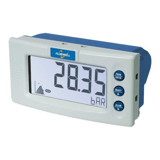
User manual D016-P Flowrate Indicator / Totalizer 1 – I NTRODUCTION The D016-P Display Functions The D016-P has a large transflective LCD with a number of symbols and digits to display measuring units, status information, trend indication and keyword messages. Figure 2: The display functions of the D016-P Indication of large Measuring units large display... -
Page 9: Available D016-P Configurations
User manual D016-P Flowrate Indicator / Totalizer – 1 NTRODUCTION Available D016-P configurations Your D016-P model is available in a number of hardwired configuration options. A product label on the backside of the unit identifies which configuration options are included in your D016-P. -
Page 10: Chapter 2: "Specifications Of The D016-P
Specifications of the D016-P CHAPTER General specifications Display Type High intensity reflective numeric and alphanumeric LCD, UV- resistant. Digits Seven 17mm (0.67") and eleven 8mm (0.31")digits. Various symbols and measuring units. Refresh rate User definable: fast - 1 sec - 3 sec - 15 sec - 30 sec - off. Option ZB Transflective LCD with bi-color LED backlight;... -
Page 11: Sensor Excitation
User manual D016-P Flowrate Indicator / Totalizer D016-P – 2 PECIFICATIONS OF THE Sensor excitation Sensor exitation specifications relate to the power supply type. Type PB / PX 3V DC for pulse signals and 1.2V DC for coil pick-up. Note: To prevent battery drainage only use for pulse sensors with a very low power consumption such as coils (sine wave) and reed-switches. -
Page 12: Operational
User manual D016-P Flowrate Indicator / Totalizer 2 – S D016-P PECIFICATIONS OF THE Type OR Isolated electro-mechanical relay (NO/NC); max. resistive load: 2A@230Vac / 30V DC. Pilot duty rating: 0,5A @ 230Vac. Requires PM/PD (DC). Note: In case of inductive load, use RC snubbers. Type OT Passive transistor output (NPN) - not isolated;... -
Page 13: Chapter 3: "Installation Instructions
Installation Instructions CHAPTER Note: This section describes various hardware configurations of the D016-P. Your particular model of the D016-P may not support all configuration options described. Mechanical Installation Figure 3: Mechanical mounting precautions To extend life of your unit: • Mount the D016-P on a solid base to avoid vibrations. •... -
Page 14: Electrical Installation - General
User manual D016-P Flowrate Indicator / Totalizer 3 – I NSTALLATION NSTRUCTIONS Electrical installation – general Overview of Terminal Connectors To gain access to the connectors open the panel containing the D016-P. You now see the battery cover with the battery and the connectors at the back side of the display unit as shown below. The actual number and size of connectors depends on your particular model. -
Page 15: Power Supply Wiring
User manual D016-P Flowrate Indicator / Totalizer – 3 NSTALLATION NSTRUCTIONS Figure 7: Voltage switch positions 8.2V Connector Types and Wiring Sizes The following connector types are fitted. Wires are connected using a flat head screw driver: Classic COMBICON A screw connector with 5.08mm pitch, suitable for 0.2—2.5mm2 or AWG 24—12 wire. - Page 16 User manual D016-P Flowrate Indicator / Totalizer 3 – I NSTALLATION NSTRUCTIONS Power wiring type PX Connect the “-”, GND or “0V” wire of your external power supply to pin P3. Connect the “+” wire to pin P4. Figure 8: Power wiring type PX D016-P 8-30Vdc With power wiring type PX pin S4 offers 8.2V to power a device in the field...
-
Page 17: Backlight
User manual D016-P Flowrate Indicator / Totalizer – 3 NSTALLATION NSTRUCTIONS Power wiring type PM Type PM is a galvanically isolated high power switching power supply, converting 115–230Vac mains (50/60Hz) to power the D016-P, the backlight (option) and provides up to 24V sensor supply to the field. -
Page 18: I/O Wiring Options
User manual D016-P Flowrate Indicator / Totalizer 3 – I NSTALLATION NSTRUCTIONS I/O wiring options Flowmeter Input Wiring Options Type P Below flowmeter signal types can be connected to the D016-P. The screen of the signal wire must be connected to the common ground if not earthed at the sensor itself. - Page 19 User manual D016-P Flowrate Indicator / Totalizer – 3 NSTALLATION NSTRUCTIONS Pulse-signal NPN / NPN-LP The D016-P is suitable for use with flowmeters which have a NPN output signal. For reliable pulse detection, the pulse amplitude has to go below 1.2V. Signal setting NPN-LP employs a low-pass signal noise filter, which limits the maximum input frequency See Low pass filter on page 12.
- Page 20 User manual D016-P Flowrate Indicator / Totalizer 3 – I NSTALLATION NSTRUCTIONS Reed Switch The D016-P is suitable for use with flowmeters which have a reed switch output signal. For reliable pulse detection a low-pass signal noise filter can be applied, which limits the pulse bounce See Low pass filter on page 12.
-
Page 21: Pulse Output Wiring
User manual D016-P Flowrate Indicator / Totalizer – 3 NSTALLATION NSTRUCTIONS Active Input Signal The D016-P is suitable for use with flowmeters which actively provide an output signal. The active output based flowmeter can be powered externally or via the 8.2/12/24Vdc sensor power terminal, provided with power supply PD and PM. -
Page 22: Passive Output, Type Ot
User manual D016-P Flowrate Indicator / Totalizer 3 – I NSTALLATION NSTRUCTIONS Passive output, Type OT Type OT provides a passive pull down output, capable of sinking 300mA@50Vdc. Figure 18: Passive output type OT D016-P load Maximum 50Vdc @ 300mA Relay Contact Output, Type OR Type OR provides a potential free output contact, capable of driving 2A @ 230V. -
Page 23: Chapter 4: "Configuring The D016-P
Configuring the D016-P CHAPTER General The D016-P has three buttons and four modes of operation, one of which is “off”. The active modes are displayed by status indicators. Configuration of the D016-P is possible via the Setup and Program modes, which are indicated by PROGRAM SETUP Warning:... -
Page 24: Quick Reference Menu
User manual D016-P Flowrate Indicator / Totalizer 4 – C D016-P ONFIGURING THE Quick Reference Menu Shelf mode Mode to deactivate the unit for storage. The unit is switched off. Press SELECT twice to switch the unit on and perform a self test. Operator mode Setup mode Program mode... -
Page 25: Modes Of Operation
User manual D016-P Flowrate Indicator / Totalizer D016-P – 4 ONFIGURING THE Modes of Operation Shelf Mode In Shelf mode the D016-P shuts down and can be shelved, stored or transported without draining the battery. All settings in EEPROM remain stored, even when the battery is removed. To wake the unit up press the center button ( /) twice to bring it in Operator mode. - Page 26 User manual D016-P Flowrate Indicator / Totalizer 4 – C D016-P ONFIGURING THE Program Mode In Program mode you can change the properties (value or setting) of a selected Function item. Warning: Not understanding the effect of your changes can cause unexpected system responses, resulting in process inefficiency, product spilling and downtime.
-
Page 27: Overview Of Setup Functions And Settings
User manual D016-P Flowrate Indicator / Totalizer D016-P – 4 ONFIGURING THE Overview of Setup Functions and Settings & ETUP FUNCTION SETTINGS DEFAULT VALUE 1 – T OTAL 11 Units , GAL, USGAL, NO UNIT 12 Decimals 0000000 - 111111.1 - 22222.22 - 3333.333 13 K-factor 0.000010 - 9,999,999 14 Decimal K-factor... -
Page 28: The D016-P Setup Functions Explained
User manual D016-P Flowrate Indicator / Totalizer 4 – C D016-P ONFIGURING THE The D016-P Setup Functions Explained Warning: Disconnect the D016-P from the process before modifying setup items: Changes to setup items take immediate effect! 1 — T ETUP OTAL Below setup items determine the calculation and visualisation of the total volume. -
Page 29: Flowrate
User manual D016-P Flowrate Indicator / Totalizer D016-P – 4 ONFIGURING THE SETUP Decimal K-factor Decimal K-factor determines the number of decimals for 13 "K-factor". The following can SETUP be selected: 0 - 1 - 2 - 3 - 4 - 5 - 6 Caution: •... -
Page 30: Total
User manual D016-P Flowrate Indicator / Totalizer 4 – C D016-P ONFIGURING THE SETUP Decimals K-factor Decimals K-factor determines the number of decimals for 24 "K-factor". The following can SETUP be selected: 0 - 1 - 2 - 3 - 4 - 5 - 6 Caution: •... -
Page 31: Power Management
User manual D016-P Flowrate Indicator / Totalizer D016-P – 4 ONFIGURING THE SETUP Brightness Brightness determines the intensity of the optionally supplied LED backlight. If no backlight has been supplied this setting has no impact. The following can be selected (from dark to bright): 1 - 2 - 3 - 4 - 5 4 —... - Page 32 User manual D016-P Flowrate Indicator / Totalizer 4 – C D016-P ONFIGURING THE 6 — L ETUP INEARIZATION The flow curve of most flowmeters is not linear but shows deviations – especially when measuring close to the beginning or end of the measuring range. The linearization function provides means to better approach the actual flow curve as with the nominal K-factor entered with 13 and 24.
-
Page 33: Linearization
User manual D016-P Flowrate Indicator / Totalizer D016-P – 4 ONFIGURING THE You can enter correction factors at flow values ranging from 0Hz to 10kHz. It is advised to enter the frequencies in increasing order, however this is not necessary. SETUP Freq. -
Page 34: Pulse Output
User manual D016-P Flowrate Indicator / Totalizer 4 – C D016-P ONFIGURING THE 7 — P ETUP ULSE OUTPUT One output can be made available as scaled pulse output, to count the accumulated total. Below setup items determine the settings for this scaled pulse output. SETUP Pulse Width Pulse Width determines the pulse width (t) of the scaled pulse output as defined in... -
Page 35: Others
User manual D016-P Flowrate Indicator / Totalizer D016-P – 4 ONFIGURING THE 8 — O ETUP THERS Below setup items identify the characteristics, location and accessibility of your D016-P. Below information may be requested when you call for support or maintenance –e.g. in the case of a serious breakdown–... -
Page 36: Chapter 5: "Operating The D016-P
Operating the D016-P CHAPTER The D016-P default mode of operation is the Operator mode. In Operator mode field information is processed and displayed. What information is displayed how depends on the configuration settings, as described in "Configuring the D016-P" on page 17 Signals, generated by the flowmeter in the field, are processed real time in the background, independent from the configured display update speed. -
Page 37: Operator Functions
User manual D016-P Flowrate Indicator / Totalizer D016-P – 5 PERATING THE Operator functions For the operator the following functions are available: Display flowrate and total or flowrate Depending on how the D016-P is configured the default operator display shows either: •... -
Page 38: Operator Alarms
User manual D016-P Flowrate Indicator / Totalizer 5 – O D016-P PERATING THE Operator alarms Low-battery alarm When the battery voltage drops starts flashing. When flashing the battery is still ok. When is on continuously, the battery is drained and MUST be replaced ASAP! Figure 26: Example of Low-Battery alarm LOW BATTERY Caution:... -
Page 39: Chapter 6: "Maintenance
Maintenance CHAPTER General directions The D016-P does not require special maintenance unless when used in • low-temperature applications, • high humidity environments (above 90% annual mean). It is the customers’ responsibility to take all precautions necessary to dehumidify the internal atmosphere of the D016-P enclosure in such a way that no condensation or ice deposition can occur. -
Page 40: Preventive Maintenance Checks
Caution: Warrantee and certification of the D016-P are waived when repairs are carried out by others than Fluidwell bv or his authorized repair centre. Repair actions that customers are allowed do themselves are • "Replacing the battery" on page 33... -
Page 41: Setup Configuration Examples
Setup Configuration Examples APPENDIX This appendix provides information and examples that might help you configure a number of setup functions. Calculating the K-factor Calculating the K-factor for Totals Below examples show ways to calculate the K-factor and corresponding decimals. Example: Calculating the K-factor for Totals (1) Let us assume that the flowmeter generates 2.4813 pulses per liter and the selected unit is m3 (see 11). - Page 42 User manual D016-P Flowrate Indicator / Totalizer A – S ETUP ONFIGURATION XAMPLES Averaging the Flowrate via a Pulse Window Some units with pulse inputs include a "Calculation / pulses" function which defines a pulse window. A pulse window represents a fixed number of pulses. The pulse window is used to average flowmeter signals known for varying pulse duty factors.
- Page 43 User manual D016-P Flowrate Indicator / Totalizer – A ETUP ONFIGURATION XAMPLES Determining the Scaled Pulse Dimensions The speed of accumulation (flowrate), pulse per amount, type of output and pulse width are related. = pulse width ≥ 2 x t = the period unit you set One period unit represents approx.
-
Page 44: Troubleshooting The D016-P
Troubleshooting the D016-P APPENDIX In this appendix several issues are described that may occur during installation or operation of your D016-P. If you have an issue that is not reported here, please contact your supplier. Response not as expected Pulse output does not function Check: •... - Page 45 User manual D016-P Flowrate Indicator / Totalizer D016-P – B ROUBLESHOOTING THE This page is left blank intentionally. FW-D016-P-MAN-EN-V0102_02...
- Page 46 User manual D016-P Flowrate Indicator / Totalizer FW-D016-P-MAN-EN-V0102_02...
- Page 47 User manual D016-P Flowrate Indicator / Totalizer – C LIST OF CONFIGURATION SETTINGS ETTINGS DEFAULT Enter your settings here 1 "T " OTAL 11 Unit 12 Decimals 0000000 13 K-factor 000001 / / sec / sec 14 Decimals K-factor 2 "F "...
- Page 48 84 Password 0000 85 Tag Number 0000000 Fluidwell bv P.O. Box 6 Voltaweg 23 T +31 (0)413 343 786 5460 AA Veghel 5466 AZ F +31 (0)413 363 443 Copyright Fluidwell bv - 2014 FW-D016-P-MAN-EN-V0102_02 The Netherlands The Netherlands E displays@fluidwell.com...
Need help?
Do you have a question about the D Series and is the answer not in the manual?
Questions and answers