
Related Manuals for Fluidwell D090-A-PL


Summary of Contents for Fluidwell D090-A-PL
- Page 1 User Manual D090-A-PL MULTI-PURPOSE INDICATOR INPUT LOOP POWERED Signal input: 4-20 mA sensor signal Options: backlight D-Series - Panel mounted indicators More info: www.fluidwell.com/dseries...
-
Page 2: Table Of Contents
Menu 2: Backlight ......................13 5.4.3 Menu 3: Sensor ......................14 5.4.4 Menu 4: Others ......................15 INSTALLATION........................16 Installation / environmental conditions ................16 Handling the D090-A-PL enclosure ................17 6.2.1 Identification........................17 Mechanical installation....................17 6.3.1 Mechanical dimensions ....................17 6.3.2 Mounting the D-Series .................... - Page 3 D090-A-PL User Manual Operational ........................23 APPENDIX B - TROUBLESHOOTING ................... 24 APPENDIX C - LEGAL INFORMATION ..................25 Declarations of Conformity ..................... 25 FW_D090-A-PL_M_v0501-01_EN Page 3...
-
Page 4: About This Manual
● incorrect functioning of the unit or connected instruments. A note informs you of important information. WARRANTY AND TECHNICAL SUPPORT For warranty and technical support on your Fluidwell products, visit our internet site www.fluidwell.com or contact us at support@fluidwell.com. MODEL REFERENCE Hardware version: 03.04.xx... -
Page 5: Safety
D090-A-PL User Manual SAFETY PERSONAL SAFETY ● Risk of electric shock: Only open the unit if all leads are free of potential electrical energy. ● Immediately inform the person responsible for the installation if you disagree with the safety precautions or if you detect errors or danger. -
Page 6: Introduction
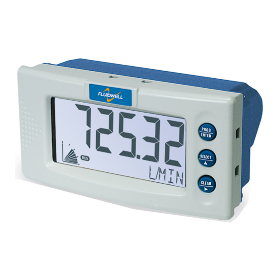
Fig. 1: The D090 This manual describes the daily use, configuration and installation of the D090-A-PL with analog 4-20 mA input from a sensor, and its available options. The following figure shows the D090-A-PL used in a typical application. -
Page 7: Installation Example
D090-A-PL User Manual INSTALLATION EXAMPLE Following parts can be recognized in below installation example. Fig. 3: Installation example D090-A-PL 1. Front cover 3. Label 5. Keys 7. Clamp 2. Display 4. Protective earth 6. Mounting panel 8. Back side cover connection... -
Page 8: Operation
Section 2: Safety [»5] INTRODUCTION This chapter describes the daily use and operation of the D090-A-PL. For this, the D-Series is equipped with a control panel that provides the operator with various functions, information and operating modes. 4.1.1... -
Page 9: Backlight (Type Zb)
4.2.2 BACKLIGHT (TYPE ZB) The D090-A-PL with Type ZB is equipped with a backlight to illuminate the display for improved readability. The backlight can be turned on or off, and its intensity can be set in the SETUP- menu. DISPLAYED INFORMATION 4.3.1... -
Page 10: Configuration
CONFIGURATION INTRODUCTION This chapter describes how technicians can use configuration settings to configure the D-Series for optimal functionality. Configuration of the D090-A-PL can be done in SETUP mode, using the front keys. CONFIGURING USING SETUP MODE For an overview of Operating modes, see Section 4.1.1: Operating modes [»8]... -
Page 11: Changing Configuration Settings
D090-A-PL User Manual 5.2.3 CHANGING CONFIGURATION SETTINGS A menu item either contains a value (a number with optionally a decimal point and sign, e.g. -123.45) or a selection list (e.g. L – m - USGAL). After a menu item is selected in the SETUP menu, a new value can be programmed by performing the following steps. -
Page 12: Setup Menu Overview
User Manual D090-A-PL SETUP MENU OVERVIEW DISPLAY DEFAULT UNIT mL - L - nL- M3 - nM3 - mg - g - kg - ton - gal - sgal - igal - lb - bbl - cf - scf - p - rev - °C - °F - K - % - m - mm - cm -... -
Page 13: Menu 2: Backlight
D090-A-PL User Manual DISPLAY UNIT Determines the measurement unit for the displayed process value. The following can be selected: mL - L - nL- M3 - nM3 - mg - g - kg - ton - gal - sgal - igal - lb - bbl - cf - scf - p - rev - °C - °F - K - % - m - mm - cm - mtr - inch - ft - psi - mbar -... -
Page 14: Menu 3: Sensor
D090-A-PL 5.4.3 MENU 3: SENSOR SENSOR FORMULA The D090-A-PL can process the analog signal in two ways: linear or as a root. Interpolation: the signal is processed in a linear way ● R = S x I Square root: the signal is processed applying a square root ●... -
Page 15: Menu 4: Others
D090-A-PL User Manual SENSOR CALIBRATE HIGH The unit is calibrated in factory using a very accurate current source. In case the sensor signal does not equal 20mA at maximum process value, this function is needed to set the input current at maximum level (offset + span). -
Page 16: Installation
Personnel must read and understand this Operating Manual before carrying out its instructions. ● The D090-A-PL may only be operated by personnel who are authorized and trained by the operator of the facility. All instructions in this manual are to be observed. -
Page 17: Handling The D090-A-Pl Enclosure
User Manual HANDLING THE D090-A-PL ENCLOSURE 6.2.1 IDENTIFICATION Identification label To identify your D090-A-PL device, all enclosures have a weatherproof identification label placed at the backside of the product. Fig. 6: Example of D0-Series identification label Serial number and year of production... -
Page 18: Mounting The D-Series
The gasket delivered with the unit must be properly mounted between the front edge of the unit and the panel, without any twists or distortions. The 4 clamps, also delivered with the unit, are needed to fix the D090-A-PL to the panel. Please follow the installation procedure: 1. -
Page 19: Protective Earth (Pe) Connections
● The wire screens shall be terminated at one side to prevent wire loops. Inside of the D090-A-PL, the different common ground terminals are connected to each other. It is advised, as illustrated, to terminate the wire screens in the vicinity of the sensor and to insulate the wire screen with a shrink tube at the D090-A-PL side. -
Page 20: Power Supply
User Manual D090-A-PL All field wiring enters the D090-A-PL from the back side and connects to the circuit assembly though terminal connectors. The wire screens (shield) are meant to prevent electromagnetic interference and shall be terminated at one side to prevent ground loops. Connection of the screen can either be made to the common ground terminal or at the sensor itself, whichever is appropriate to the application. -
Page 21: Maintenance
Personnel must read and understand this Operating Manual before carrying out its instructions. ● The D090-A-PL may only be operated by personnel who are authorized and trained by the operator of the facility. All instructions in this manual are to be observed. -
Page 22: Appendix A - Technical Specification
User Manual D090-A-PL APPENDIX A - TECHNICAL SPECIFICATION GENERAL DISPLAY Type High intensity reflective numeric and alphanumeric LCD, UV-resistant Digits 5½ with height 26mm (1”) and 11 with height 8mm (0.31”). Various symbols and measuring units. Dimensions 90 x 40 mm (3.5” x 1.6”) -
Page 23: Input
D090-A-PL User Manual INPUT SENSOR Signal type 4-20 mA, with signal calibration feature Accuracy 16 bit. Error < 0.01 mA or ±0.05% FS. Low-level cut-off programmable. Span 0.00001 to 199.999 with variable decimal position. Offset -99.999 - +199.999 Update time... -
Page 24: Appendix B - Troubleshooting
APPENDIX B - TROUBLESHOOTING Table 1 lists and describes how to troubleshoot problems that can occur when installing or operating the D090-A-PL. Table 2 lists internal alarm codes and conditions signaled by a blinking ALARM flag on the display ). Press the SELECT key several times to display the 4-digit error code shown in Table 2. -
Page 25: Appendix C - Legal Information
EU De cla tio n of Conformi Fluidwell 0 D ‒Series indicators he , February 2022 We, Fluidwell BV, declare under our s e ol respons ibility that the 0 D ‒Series indicators are de igne d and will operate conform the following applicable European... - Page 26 User Manual D090-A-PL LIST OF CONFIGURATION SETTINGS SETTING DEFAULT DATE: DATE: DISPLAY UNIT TIME UNIT DECIMALS OFFSET SPAN 1600 DIRECTION normal CURRENT PERCENTAGE BARGRAPH BACKLIGHT BACKLIGHT BACKLIGHT BRIGHTNESS SENSOR FORMULA interpolation FILTER 01 (off) CALIBRATE LOW factory CALIBRATE HIGH factory...
- Page 27 D090-A-PL User Manual NOTES FW_D090-A-PL_M_v0501-01_EN Page 27...
- Page 28 Fluidwell bv P.O. Box 6 Voltaweg 23 Website: www.fluidwell.com 5460 AA Veghel 5466 AZ Veghel Find your nearest representative: www.fluidwell.com/representatives the Netherlands the Netherlands © Copyright 2024 - FW_D090-A-PL_M_v0501-01_EN...
Need help?
Do you have a question about the D090-A-PL and is the answer not in the manual?
Questions and answers