
Related Manuals for Fluidwell D Series


Summary of Contents for Fluidwell D Series
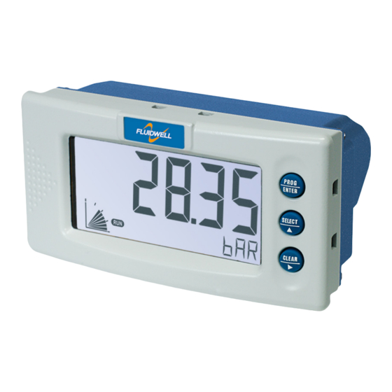
- Page 1 D013-A LOWRATE ONITOR OTALIZER WITH LARM OUTPUT Signal input flowmeter: (0)4-20mA Output: High and Low alarm Fluidwell D-Series Indicators - The better alternative for DIN panel mount indicators...
- Page 2 User manual D013-A Flowrate Monitor / Totalizer Health and Safety Information Caution: The D013-A must only be installed, operated and maintained by competent personnel that received proper training on regular basis, including instructions on the various types of protection and installation practices, relevant rules and regulations, and the general principles of area classification.
-
Page 3: Read Me First
D013-A Flowrate Monitor / Totalizer. Information in this manual is subject to change without prior notice. Fluidwell bv is not responsible for mistakes in this material or for incidental damage caused as a direct or indirect result of the delivery, performance or use of this material. -
Page 4: Table Of Contents
User manual D013-A Flowrate Monitor / Totalizer How To Read This Manual Caution: • Before operating, configuring, opening or installing the D013-A you are expected to have read and understood all relevant sections in this manual. • Before operation the D013-A MUST be installed in compliance with the installation instructions as described in "Installation Instructions"... - Page 5 Contents Read Me First! About This Guide ............iii Prerequisites.
- Page 6 User manual D013-A Flowrate Monitor / Totalizer 1 – C ONTENTS 4 Configuring the D013-A General ..............17 The D013-A Display Functions .
-
Page 7: Chapter 1: "Introduction
Introduction CHAPTER System Description of the D013-A Functions and Features The Flowrate Monitor / Totalizer model D013-A is a microprocessor controlled device to linearise the flowmeters flowcurve and to display flowrate, total and accumulated total as well as to generate a scaled pulse according the accumulated total. The D013-A has been designed with a focus on: •... -
Page 8: The D013-A Display Functions
User manual D013-A Flowrate Monitor / Totalizer 1 – I NTRODUCTION The D013-A Display Functions The D013-A has a large transflective LCD with a number of symbols and digits to display measuring units, status information, trend indication and keyword messages. Figure 2: The display functions of the D013-A Indication of large Measuring units large display... -
Page 9: Available D013-A Configurations
User manual D013-A Flowrate Monitor / Totalizer – 1 NTRODUCTION Available D013-A configurations Your D013-A model is available in a number of hardwired configuration options. A product label on the backside of the unit identifies which configuration options are included in your D013-A. - Page 10 User manual D013-A Flowrate Monitor / Totalizer 1 – I NTRODUCTION This page is left blank intentionally. FW-D013-A-MAN-EN-V0102_02...
-
Page 11: Chapter 2: "Specifications Of The D013-A
Specifications of the D013-A CHAPTER General specifications Display Type High intensity reflective numeric and alphanumeric LCD, UV- resistant. Digits Seven 17mm (0.67") and eleven 8mm (0.31")digits. Various symbols and measuring units. Refresh rate User definable: fast - 1 sec - 3 sec - 15 sec - 30 sec - off. Option ZB Transflective LCD with bi-color LED backlight;... -
Page 12: Sensor Excitation
User manual D013-A Flowrate Monitor / Totalizer 2 – S D013-A PECIFICATIONS OF THE Sensor excitation Sensor exitation specifications relate to the power supply type. Type PB / PX Not available Type PD / PM Dipswitch adjustable sensor supply: 8.2V DC. Iout max 35mA @ 20°C 12V DC. -
Page 13: Operational
User manual D013-A Flowrate Monitor / Totalizer D013-A – 2 PECIFICATIONS OF THE Operational Operator functions Displayed functions • total and / or flowrate • total and accumulated total Note: Total can be reset to zero by pressing the CLEAR-key twice. •... - Page 14 User manual D013-A Flowrate Monitor / Totalizer 2 – S D013-A PECIFICATIONS OF THE This page is left blank intentionally. FW-D013-A-MAN-EN-V0102_02...
-
Page 15: Chapter 3: "Installation Instructions
Installation Instructions CHAPTER Note: This section describes various hardware configurations of the D013-A. Your particular model of the D013-A may not support all configuration options described. Mechanical Installation Figure 3: Mechanical mounting precautions To extend life of your unit: • Mount the D013-A on a solid base to avoid vibrations. •... -
Page 16: Electrical Installation - General
User manual D013-A Flowrate Monitor / Totalizer 3 – I NSTALLATION NSTRUCTIONS Electrical installation – general Overview of Terminal Connectors To gain access to the connectors open the panel containing the D013-A. You now see the battery cover with the battery and the connectors at the back side of the display unit as shown below. The actual number and size of connectors depends on your particular model. -
Page 17: Power Supply Wiring
User manual D013-A Flowrate Monitor / Totalizer – 3 NSTALLATION NSTRUCTIONS Connector Types and Wiring Sizes The following connector types are fitted. Wires are connected using a flat head screw driver: Classic COMBICON A screw connector with 5.08mm pitch, suitable for 0.2—2.5mm2 or AWG 24—12 wire. - Page 18 User manual D013-A Flowrate Monitor / Totalizer 3 – I NSTALLATION NSTRUCTIONS Power wiring type PX Connect the “-”, GND or “0V” wire of your external power supply to pin P3. Connect the “+” wire to pin P4. Figure 8: Power wiring type PX D013-A 8-30Vdc With power wiring type PX pin S4 offers 8.2V to power a device in the field...
- Page 19 User manual D013-A Flowrate Monitor / Totalizer – 3 NSTALLATION NSTRUCTIONS Power wiring type PM Type PM is a galvanically isolated high power switching power supply, converting 115–230Vac mains (50/60Hz) to power the D013-A, the backlight (option) and provides up to 24V sensor supply to the field.
- Page 20 User manual D013-A Flowrate Monitor / Totalizer 3 – I NSTALLATION NSTRUCTIONS I/O wiring options Flowmeter Input Wiring Options Type A The D013-A requires a 0(4)–20mA input signal which will be processed 4 times a second with a 14 bit accuracy. Sensors that are not externally/self powered can by powered by the sensor supply terminal, when the D013-A is equipped with power supply type PD.
-
Page 21: Alarm Output Wiring
User manual D013-A Flowrate Monitor / Totalizer – 3 NSTALLATION NSTRUCTIONS Alarm output wiring Active / Passive output, Type OH Type OH provides an active pull up output and a passive pull down output. The active pull up output is capable of sourcing 75mA depending on the power supply used. Note that for the AC supplied inputs the total output current is reduced by the used nominal D013-A current. -
Page 22: Relay Contact Output, Type Or
User manual D013-A Flowrate Monitor / Totalizer 3 – I NSTALLATION NSTRUCTIONS Relay Contact Output, Type OR Type OR provides a potential free output contact, capable of driving 2A @ 230V. When used for switching loads on another relay or solenoid valve coils the pilot duty rating is 0,5A @ 230Vac Note that (configured) output frequencies of 5Hz or higher reduce relay life time significantly. -
Page 23: Chapter 4: "Configuring The D013-A
Configuring the D013-A CHAPTER General The D013-A has three buttons and four modes of operation, one of which is “off”. The active modes are displayed by status indicators. Configuration of the D013-A is possible via the Setup and Program modes, which are indicated by PROGRAM SETUP Warning:... -
Page 24: Quick Reference Menu
User manual D013-A Flowrate Monitor / Totalizer 4 – C D013-A ONFIGURING THE Quick Reference Menu Shelf mode Mode to deactivate the unit for storage. The unit is switched off. Press SELECT twice to switch the unit on and perform a self test. Operator mode Setup mode Program mode... -
Page 25: Modes Of Operation
User manual D013-A Flowrate Monitor / Totalizer D013-A – 4 ONFIGURING THE Modes of Operation Shelf Mode In Shelf mode the D013-A shuts down and can be shelved, stored or transported without draining the battery. All settings in EEPROM remain stored, even when the battery is removed. To wake the unit up press the center button ( /) twice to bring it in Operator mode. - Page 26 User manual D013-A Flowrate Monitor / Totalizer 4 – C D013-A ONFIGURING THE Program Mode In Program mode you can change the properties (value or setting) of a selected Function item. Warning: Not understanding the effect of your changes can cause unexpected system responses, resulting in process inefficiency, product spilling and downtime.
-
Page 27: Overview Of Setup Functions And Settings
User manual D013-A Flowrate Monitor / Totalizer D013-A – 4 ONFIGURING THE Overview of Setup Functions and Settings & ETUP FUNCTION SETTINGS DEFAULT VALUE 1 – T OTAL 11 Units , GAL, USGAL, NO UNIT 12 Decimals 0000000 - 111111.1 - 22222.22 - 3333.333 13 Span 0.000010 - 9,999,999 14 Decimal Span... -
Page 28: The D013-A Setup Functions Explained
User manual D013-A Flowrate Monitor / Totalizer 4 – C D013-A ONFIGURING THE The D013-A Setup Functions Explained Warning: Disconnect the D013-A from the process before modifying setup items: Changes to setup items take immediate effect! 1 — T ETUP OTAL Below setup items determine the calculation and visualisation of the total volume. - Page 29 User manual D013-A Flowrate Monitor / Totalizer D013-A – 4 ONFIGURING THE 2 — F ETUP LOWRATE Below setup items determine the calculation and visualisation of the flowrate. • For configuration examples to calculate the span see "Calculating the span for flowrate" on page 37.
-
Page 30: Alarm
User manual D013-A Flowrate Monitor / Totalizer 4 – C D013-A ONFIGURING THE 3 — A ETUP LARM Below setup items determine the alarm features that can be set for Pulse monitoring. When set, alarms activate as soon as –and as long as– the Pulse exceeds the corresponding alarm value. -
Page 31: Total
User manual D013-A Flowrate Monitor / Totalizer D013-A – 4 ONFIGURING THE 4 — D ETUP ISPLAY Below setup options define the display functions for the operator. SETUP Function Function defines the function of the large (upper) display readout and the small (lower) display readout. -
Page 32: Power Management
User manual D013-A Flowrate Monitor / Totalizer 4 – C D013-A ONFIGURING THE 5 — P ETUP OWER ANAGEMENT Below setup options are smart power management functions to set the optimum between the response time of the unit and the (optional) battery life time. SETUP LCD New LCD New defines the display update frequency when the D013-A is unmanned (no buttons... -
Page 33: Flowmeter
User manual D013-A Flowrate Monitor / Totalizer D013-A – 4 ONFIGURING THE 6 — F ETUP LOWMETER Below setup items adjust the D013-A to accomodate to your type of flowmeter signal. SETUP Formula Depending on the type of flowmeter, the flowmeter signal from the field is either linear to the actual flowrate, or a square of the actual flowrate. - Page 34 User manual D013-A Flowrate Monitor / Totalizer 4 – C D013-A ONFIGURING THE Note: A filter allows for a more stable but less detailed flowrate readout. The higher the filter level, the better it will filter out disturbances. But also: the slower the response on a value change! Figure 21: Filter response on calculated step changes and oscillation Slow response on step change...
- Page 35 User manual D013-A Flowrate Monitor / Totalizer D013-A – 4 ONFIGURING THE SETUP Cut-Off Cut-Off determines the amount of low-flow to ignore, due to e.g. expected leakage or vibration. If the measured flowrate is below the cut-off value, no flow is processed and the total counters are not incremented.
-
Page 36: Others
User manual D013-A Flowrate Monitor / Totalizer 4 – C D013-A ONFIGURING THE SETUP Calibrate High / 20mA Calibrate High / 20mA allows you to tune the analog input value that represents maximum flowrate. Warning: Do not tune while the D013-A is processing data! •... - Page 37 User manual D013-A Flowrate Monitor / Totalizer D013-A – 4 ONFIGURING THE SETUP Tag Number For identification and communication purposes, a unique tagnumber of maximum 7 digits can be entered. Tag Number determines the value of the tag number. 0000000 - 9999999 (7 digit numeric) FW-D013-A-MAN-EN-V0102_02...
-
Page 38: Chapter 5: "Operating The D013-A
Operating the D013-A CHAPTER The D013-A default mode of operation is the Operator mode. In Operator mode field information is processed and displayed. What information is displayed how depends on the configuration settings, as described in "Configuring the D013-A" on page 17 Signals generated by the flowmeter in the field are processed real time in the background, independent from the configured display update speed. -
Page 39: Operator Functions
User manual D013-A Flowrate Monitor / Totalizer D013-A – 5 PERATING THE Operator functions For the operator the following functions are available: Display flowrate and total or flowrate Depending on how the D013-A is configured the default operator display shows either: •... -
Page 40: Operator Alarms
User manual D013-A Flowrate Monitor / Totalizer 5 – O D013-A PERATING THE Operator alarms Low-battery alarm When the battery voltage drops starts flashing. When flashing the battery is still ok. When is on continuously, the battery is drained and MUST be replaced ASAP! Figure 24: Example of Low-Battery alarm LOW BATTERY Caution:... -
Page 41: Chapter 6: "Maintenance
Maintenance CHAPTER General directions The D013-A does not require special maintenance unless when used in • low-temperature applications, • high humidity environments (above 90% annual mean). It is the customers’ responsibility to take all precautions necessary to dehumidify the internal atmosphere of the D013-A enclosure in such a way that no condensation or ice deposition can occur. -
Page 42: Preventive Maintenance Checks
Caution: Warrantee and certification of the D013-A are waived when repairs are carried out by others than Fluidwell bv or his authorized repair centre. Repair actions that customers are allowed do themselves are • "Replacing the battery" on page 35... -
Page 43: Setup Configuration Examples
Setup Configuration Examples APPENDIX This appendix provides information and examples that might help you configure a number of setup functions. Calculating the Span Calculating the Span for Totals Below examples show ways to calculate the span and corresponding decimals. Example: Calculating the Span for Totals (1) Let us assume that the flowmeter generates 20mA at a rate of 652.31 USGAL per hour, the selected unit is barrels (see 11). - Page 44 User manual D013-A Flowrate Monitor / Totalizer A – S ETUP ONFIGURATION XAMPLES Flowmeter Settings Analog Flowmeter Signal Filtering Flowmeter signal filtering can be done on the analog input (before processing by the D013-A) For details on filtering flowmeter signals, see "Setting up an analog fillter" on page 39. Tuning in Analog Input Tuning the analog Input is recommended when you: •...
- Page 45 User manual D013-A Flowrate Monitor / Totalizer – A ETUP ONFIGURATION XAMPLES Setting up an analog fillter Filters dampen undesired oscillations in your analog input –before processing. Such oscillations can be caused by intermittent or step changes in the field, or by the effects of sampling that (in rare cases) can cause harmonic disturbance.
-
Page 46: Troubleshooting The D013-A
Troubleshooting the D013-A APPENDIX In this appendix several issues are described that may occur during installation or operation of your D013-A. If you have an issue that is not reported here, please contact your supplier. Flowrate displays “0 / zero” while there is flow Check: •... - Page 47 User manual D013-A Flowrate Monitor / Totalizer FW-D013-A-MAN-EN-V0102_02...
- Page 48 74 Password 0000 75 Tag Number 0000000 Fluidwell bv P.O. Box 6 Voltaweg 23 T +31 (0)413 343 786 5460 AA Veghel 5466 AZ F +31 (0)413 363 443 Copyright Fluidwell bv - 2013 FW-D013-A-MAN-EN-V0102_02 The Netherlands The Netherlands E displays@fluidwell.com...
Need help?
Do you have a question about the D Series and is the answer not in the manual?
Questions and answers