
Related Manuals for Mitsubishi Electric AJ65BT-D62


Summary of Contents for Mitsubishi Electric AJ65BT-D62
- Page 1 High-Speed Counter Module Type AJ65BT-D62/AJ65BT-D62D/AJ65BT-D62D-S1 User's Manual Downloaded from ManualsNet.com search engine...
- Page 2 Downloaded from ManualsNet.com search engine...
-
Page 3: Safety Precautions
SAFETY PRECAUTIONS (Read these precautions before using this product.) Before using this product, please read this manual and the relevant manuals carefully and pay full attention to safety to handle the product correctly. The precautions given in this manual are concerned with this product only. For the safety precautions of the programmable controller system, refer to the user's manual for the CPU module used. - Page 4 [Installation Precautions] CAUTION Use the module in an environment that conforms to the general specifications in the manual. Otherwise, an electric shock, fire, misoperation or product damage or deterioration can occur. Securely fix the module using the DIN rail or mounting screws and fully tighten the mounting screws within the specified torque range.
- Page 5 [Wiring Precautions] CAUTION Always secure the wires or cables connected to the module, e.g. run them in conduits or clamp them. Otherwise, the module or cables can be damaged due to dangling, moved or accidentally pulled cables or misoperation can occur due to improper cable connection. ...
- Page 6 [Starting and Maintenance Precautions] CAUTION Do not touch the terminals while the power is on. Doing so may cause malfunction. Do not drop or apply strong shock to the module. Failure to do so may damage the module. ...
-
Page 7: Conditions Of Use For The Product
CONDITIONS OF USE FOR THE PRODUCT (1) Mitsubishi programmable controller ("the PRODUCT") shall be used in conditions; i) where any problem, fault or failure occurring in the PRODUCT, if any, shall not lead to any major or serious accident; and ii) where the backup and fail-safe function are systematically or automatically provided outside of the PRODUCT for the case of any problem, fault or failure occurring in the PRODUCT. -
Page 8: Revisions
REVISIONS *The manual number is given on the bottom left of the back cover. Print Date *Manual Number Revision Oct.,1997 IB(NA)-66823-A First edition Mar.,2000 IB(NA)-66823-B Contents of 3.4 greatly changed Output signal list in 3.7 (2) modified Partial correction made to POINT in 7.3 Partial addition made to contents of 10.2 Partial addition made to Appendix 1 Partial correction made to 4.2.1 (2) - Page 9 This manual confers no industrial property rights or any right of any other kind, nor does it confer any patent licenses. Mitsubishi Electric Corporation cannot be held responsible for any problems involving industrial property rights which may occur as a result of using the contents noted in this manual.
-
Page 10: Table Of Contents
INTRODUCTION Thank you for the Mitsubishi MELSEC-A Series of General Purpose Programmable Controllers. Please read this manual carefully so that equipment is used to its optimum. A copy of this manual should be forwarded to the end user. CONTENTS SAFETY PRECAUTIONS ..........................A- 1 CONDITIONS OF USE FOR THE PRODUCT .................... - Page 11 4.6.4 Wiring examples of controller and external input (PRESET, F.START) terminals ......4-14 4.6.5 Wiring examples of external output (EQU1, EQU2) terminals ............4-15 5. PULSE INPUT AND COUNTING METHOD 5- 1 to 5- 4 5.1 1-phase pulse input ..........................5- 2 5.2 2-phase pulse input ..........................
- Page 12 10.4.1 When preset is made by sequence program ................10-15 10.4.2 Program example of preset with sequence program ..............10-16 10.4.3 Program example of preset with external control signal ............. 10-17 10.4.4 Program example of ring counter function .................. 10-18 10.4.5 Program example of count disable function ................
-
Page 13: Manuals
MANUALS The manuals related to this product are listed below. Please place an order as needed. Related Manuals Manual No. Manual Name (Model Code) CC-Link System Master · Local Module type AJ61BT11/A1SJ61BT11 User’s Manual Describes the system configuration, performance specifications, functions, handling, IB-66721 wiring and troubleshooting of the AJ61BT11 and A1SJ61BT11. -
Page 14: General Name And Abbreviation
GENERAL NAME AND ABBREVIATION Unless otherwise specified, this manual describes the AJ65BT-D62/AJ65BT- D62D/AJ65BT-D62D-S1 type high-speed counter module using general name and abbreviation described below: General name/abbreviation Description of general name and abbreviation GX Developer Product name of the software package for the MELSEC programmable controllers... -
Page 15: Packing List
The following items are included in the package of this product. Product name Quantity AJ65BT-D62 type high-speed counter module AJ65BT-D62D type high-speed counter module AJ65BT-D62D-S1 type high-speed counter module AJ65BT-D62/AJ65BT-D62D/AJ65BT-D62D-S1 type high-speed counter module user's manual (Hardware) A - 13 Downloaded from ManualsNet.com search engine... -
Page 16: Introduction
1. INTRODUCTION This user's manual describes specifications, handling, and programming of the AJ65BT-D62/ D62D/ D62D-S1 high-speed counter modules (hereafter abbreviated as high-speed counter module) to be used in a CC-Link system. The high-speed counter module can import and count pulses of a pulse generator which cannot be imported by a programmable controller CPU. - Page 17 1. INTRODUCTION MELSEC-A The following diagram outlines how the high-speed counter module operates. 4) I/O signal Master module Read/write from/to remote register Pulse Pulse generator Encoder 3) Coincidence output To CH1 External (2 points) control signal Controller Preset counter function selection Pulse Pulse generator...
-
Page 18: Features
1. INTRODUCTION MELSEC-A 1.1 Features The high-speed counter module has the following features. (1) Pulses can be counted in a wide range from 0 to 16777215. The count value is stored in 24-bit binary. (2) Count value can be multiplied. Multiplication by either one or two can be selected for 1-phase pulse inputs, or multiplication by one, two or four for 2-phase pulse inputs. -
Page 19: System Configuration
2. SYSTEM CONFIGURATION MELSEC-A 2. SYSTEM CONFIGURATION This chapter describes a system configuration using the high-speed counter module. 2.1 Overall Configuration The overall configuration using the high-speed counter module is shown below. 2 - 1 Downloaded from ManualsNet.com search engine... -
Page 20: Applicable System
<Large type> <Small type> MITSUBISHI CPU UNIT PROGRAMMABLE CONTROLLER MODEL DATE 9707 DATE 9707 MITSUBISHI ELECTRIC CORPORATION JAPAN BD992D008H40 MITSUBISHI ELECTRIC BD992D008H40 Manufacturing Function version Manufacturing Function version year and month year and month (2) Limitations for use of dedicated command (RLPA, RRPA) for CC-Link The dedicated command (RLPA, RRPA) for CC-Link may not be used depending on the programmable controller CPU and the master module. -
Page 21: Specifications
3. SPECIFICATIONS MELSEC-A 3. SPECIFICATIONS 3.1 General Specifications The following table lists the general specifications of the high-speed counter module.(common to the AJ65BT-D62, AJ65BT-D62D and AJ65BT-D62D-S1) Item Specifications Operating ambient 0 to 55°C temperature Storage ambient -20 to 75°C temperature... -
Page 22: Performance Specifications
3. SPECIFICATIONS MELSEC-A 3.2 Performance Specifications The following table gives the performance specifications of the high-speed counter module. (1) Performance specifications of the AJ65BT-D62 Item Specifications Counting speed setting switch HIGH position LOW position Number of channels 2 channels Phase... - Page 23 3. SPECIFICATIONS MELSEC-A *Counting speed is influenced by pulse rise time and fall time. Countable speeds are as follows. Note that counting of a pulse having long rise and fall times may result in miscounting. Counting Speed HIGH Setting Switch 1-phase 2-phase 1-phase...
- Page 24 3. SPECIFICATIONS MELSEC-A (2) Performance specifications of the AJ65BT-D62D Item Specifications Counting speed setting switch HIGH position LOW position Number of channels 2 channels Count Phase 1-phase input, 2-phase input input Signal level EIA Standard RS-422-A differential type line driver level signal ( A, B) {equivalent to AM26LS31 (Japan Texas Instruments make)}...
- Page 25 3. SPECIFICATIONS MELSEC-A *Counting speed is influenced by pulse rise time and fall time. Countable speeds are as follows. Note that counting of a pulse having long rise and fall times may result in miscounting. Counting Speed HIGH Setting Switch 1-phase 2-phase 1-phase...
- Page 26 3. SPECIFICATIONS MELSEC-A (3) Performance specifications of the AJ65BT-D62D-S1 Item Specifications Counting speed setting switch HIGH position LOW position Number of channels 2 channels Count Phase 1-phase input, 2-phase input input Signal level EIA Standard RS-422-A differential type line driver level signal ( A, B) {equivalent to AM26LS31 (Japan Texas Instruments make)}...
- Page 27 3. SPECIFICATIONS MELSEC-A *Counting speed is influenced by pulse rise time and fall time. Countable speeds are as follows. Note that counting of a pulse having long rise and fall times may result in miscounting. Counting Speed HIGH Setting Switch 1-phase 2-phase 1-phase...
-
Page 28: Functions
3. SPECIFICATIONS MELSEC-A 3.3 Functions The following table lists the high-speed counter module functions. Name Description Refer To Outputs an ON/OFF signal in a specified output status, comparing Section Coincidence output function it with the present value. Counting alternates between the preset value and the ring counter value. -
Page 29: Interfaces With External Devices
3. SPECIFICATIONS MELSEC-A 3.4 Interfaces with External Devices The following tables give lists of the interfaces of the high-speed counter module with external devices. (1) Interfaces of the AJ65BT-D62 with external devices Operating Input/ Terminal Input Voltage Internal Circuit Signal Name... - Page 30 3. SPECIFICATIONS MELSEC-A (2) Interfaces of the AJ65BT-D62D with external devices Operating Input/ Terminal Input Voltage Internal Circuit Signal Name ON/OFF Current Output Number (Guaranteed) (Guaranteed) Phase A pulse (15) input EIA Standard RS-422-A line receiver (AM26C32 (manufactured by Texas Instruments Japan Limited.) or equivalent) Phase A pulse The specifications of line receiver are as...
- Page 31 3. SPECIFICATIONS MELSEC-A (3) Interfaces of the AJ65BT-D62D-S1 with external devices Operating Input/ Terminal Input Voltage Internal Circuit Signal Name ON/OFF Current Output Number (Guaranteed) (Guaranteed) Phase A pulse (16) input Phase A pulse (17) input EIA Standard RS-422-A line receiver Input (AM26C32 (manufactured by Texas Instruments Japan Limited.) or equivalent)
-
Page 32: I/O Signals Transferred To/From The Master Module
3. SPECIFICATIONS MELSEC-A 3.5 I/O Signals Transferred to/from the Master Module This section explains the input/output signals (RX, RY) of the high-speed counter module transferred to/from the master module. (1) Input signals The following table lists the input signals of the high-speed counter module transmitted to the master module. - Page 33 3. SPECIFICATIONS MELSEC-A (2) Output signals The following table lists the output signals transmitted by the master module to the high-speed counter module. ···Valid on leading edge(OFF to ON) of signal ···Valid while signal is ON. Input Signals Signal Name Operation Master module high-speed...
-
Page 34: Remote Register Allocation
3. SPECIFICATIONS MELSEC-A 3.6 Remote Register Allocation The following table gives the assignment of the remote registers in the high-speed counter module. The initial values of the remote registers are set when power is switched on or the programmable controller CPU is reset. Transmission Addresses Initial... -
Page 35: Applicable Encoders
MELSEC-A 3.7 Applicable Encoders The following encoders may be connected to the high-speed counter module. (1) Encoders connectable to the AJ65BT-D62 (a) Open collector type encoder (b) CMOS output type encoder (Make sure that the output voltage of the encoder complies with the specifications of the module.) -
Page 36: Data Link Processing Times
3. SPECIFICATIONS MELSEC-A 3.8 Data Link Processing Times In the high-speed counter module, it takes data link processing time described in this section to execute each function. For link scan time, refer to the user's manual for the master module used. As an example, this section explains processing times at *1 to *4 in a coincidence output operation. - Page 37 3. SPECIFICATIONS MELSEC-A *1 Master station (RY) remote device station (RY) processing time (Normal value) The following is the processing time takes for the remote device station to start pulse input when the count enable signal {RY(n+1)4 (RY(n+1)B)} is turned on. [Formula] SM+LS×1+remote device station processing time(1ms) [ms] high-speed counter module...
- Page 38 3. SPECIFICATIONS MELSEC-A *4 Master station (RWw) remote device station (RWw) processing time The following is the transmission time to set coincidence output point No.1 set value at the remote device station. [Formula] SM+LS×1+remote device station processing time(1ms) [ms] high-speed counter module SM: Scan time of master station sequence program LS : Link scan time 3 - 18...
-
Page 39: Installation And Pre-Operation Setting Procedure
4. INSTALLATION AND PRE-OPERATION SETTING PROCEDURE MELSEC-A 4. INSTALLATION AND PRE-OPERATION SETTING PROCEDURE This chapter describes the pre-operation procedure of the high-speed counter module, the names and settings of each part, and the wiring method. 4.1 Pre-Operation Setting Procedure Use the following procedure to make pre-operation setting for the high-speed counter module. -
Page 40: Installation
4. INSTALLATION AND PRE-OPERATION SETTING PROCEDURE MELSEC-A 4.2 Installation This section gives the handling instructions to be followed from unpacking to installation of the high-speed counter module and its installation environment. 4.2.1 Handling instructions This section gives the handling instructions of the high-speed counter module. ... -
Page 41: Installation Environment
4. INSTALLATION AND PRE-OPERATION SETTING PROCEDURE MELSEC-A (2) When using the DIN rail adapter, note the following in mounting the DIN rail. (a) Applicable DIN rail type (conforming to JIS C2812) TH35-7.5Fe TH35-7.5Al (b) DIN rail mounting screw pitch When mounting the DIN rail, tighten screws in 200mm(7.88inch) or less pitch. 4.2.2 Installation environment When installing the module, avoid the following environment. -
Page 42: Part Names And Settings
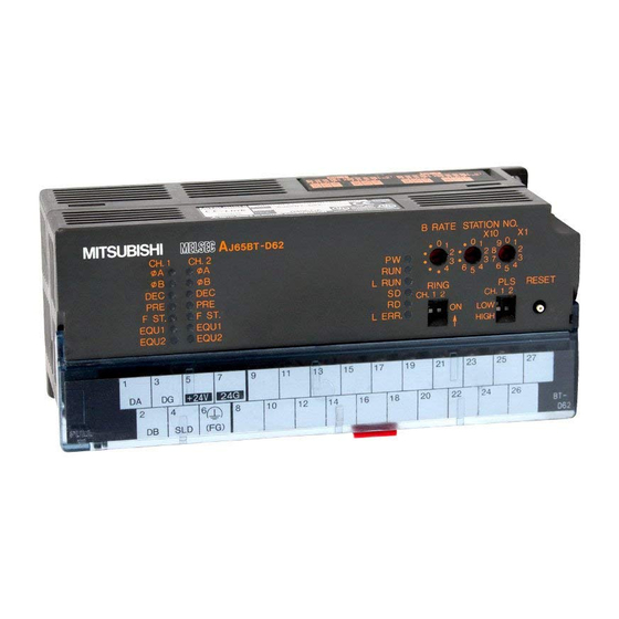
HIGH position: Up to 400(200)kPPS can be counted for 1-phase input or up to 300 (200)kPPS for 2-phase input. HIGH Values in parentheses are those for use of the AJ65BT-D62. (Factory setting: HIGH position) Ring counter setting switch Used to select whether the ring counter function is used or not. - Page 43 Lit to indicate that the coincidence output setting No. 2 is equal to the counter EQU2 value. (The AJ65BT-D62D-S1 does not have this LED.) Terminal block Pin-to-signal correspondences are indicated below. For the AJ65BT-D62 Signal name Signal name Number Number PRESET F.G.
- Page 44 4. INSTALLATION AND PRE-OPERATION SETTING PROCEDURE MELSEC-A Number Name Description Terminal block For the AJ65BT-D62D Signal name Signal name Number Number PRESET F.G. F.START EQU1 EQU2 EQU1 EQU2 PRESET 12/24V F.START For the AJ65BT-D62D-S1 Signal name Signal name Number Number PRESET F.G.
- Page 45 4. INSTALLATION AND PRE-OPERATION SETTING PROCEDURE MELSEC-A Number Name Description The also applies to CH2. Pulse/external input voltage setting pins AJ65BT-D62 Circuit board CH.1 F ST. Jumper (Jumper connected to 5V) AJ65BT-D62D CH.1 F ST. (Jumper connected to 12V) AJ65BT-D62D-S1 CH.1...
-
Page 46: Station Number Setting
4. INSTALLATION AND PRE-OPERATION SETTING PROCEDURE MELSEC-A 4.4 Station Number Setting The buffer memory addresses of the master module, where the remote I/O signals and read/write data are stored, are determined by the station number setting of the high-speed counter module. For details, refer to the user's manual (details) of the used master module. -
Page 47: Wiring
4. INSTALLATION AND PRE-OPERATION SETTING PROCEDURE MELSEC-A 4.6 Wiring 4.6.1 Connection of cables with the modules The following diagram shows the wiring of the master module, remote module and high-speed counter module with dedicated cable for CC-Link. [Sketch] POINT The "terminal resistors" supplied with the master module must be connected to the modules at both ends of data link. -
Page 48: Instructions For Wiring Pulse Generator
4. INSTALLATION AND PRE-OPERATION SETTING PROCEDURE MELSEC-A 4.6.2 Instructions for wiring pulse generator When connecting a pulse generator to the high-speed counter module, take the following precautions. (1) When using high speed pulse inputs, take the following precautions against noise (a) Always use shielded twisted cables. -
Page 49: Wiring Examples Of Pulse Generators
4.6.3 Wiring examples of pulse generators (1) Pulse generator is open collector output type (24VDC) POINT When wiring the AJ65BT-D62 and encoder, separate the power supply and signal lines as shown below. Incorrect Wiring Example Since the same twisted wire is... - Page 50 4. INSTALLATION AND PRE-OPERATION SETTING PROCEDURE MELSEC-A (2) Pulse generator is voltage output type (5VDC) REMARK * ..... Set the pulse input voltage setting pins in the position. 4 - 12 Downloaded from ManualsNet.com search engine...
- Page 51 4. INSTALLATION AND PRE-OPERATION SETTING PROCEDURE MELSEC-A (3) Pulse generator is line driver (equivalent to AM26LS31) 4 - 13 Downloaded from ManualsNet.com search engine...
-
Page 52: Wiring Examples Of Controller And External Input (Preset, F.start) Terminals
4. INSTALLATION AND PRE-OPERATION SETTING PROCEDURE MELSEC-A 4.6.4 Wiring examples of controller and external input (PRESET, F.START) terminals (1) Controller (sink load type) is 12V (2) Controller (source load type) is 5V REMARK * ..... Set the external input voltage setting pins in the position. -
Page 53: Wiring Examples Of External Output (Equ1, Equ2) Terminals
4.6.5 Wiring examples of external output (EQU1, EQU2) terminals When using the EQU terminals, a 10.2VDC to 30VDC external power supply is required to activate the internal photocoupler. Connection methods are as follows. (1) AJ65BT-D62, AJ65BT-D62D (2) AJ65BT-D62D-S1 POINT Even when not using an EQU terminal, wire the 12/24V terminal (pin number: 26) and the COM terminal (pin number: 27) to an external power supply. -
Page 54: Pulse Input And Counting Method
5. PULSE INPUT AND COUNTING METHOD MELSEC-A 5. PULSE INPUT AND COUNTING METHOD This chapter describes the pulse input and counting modes of the high-speed counter module. (1) The pulse input mode is classified into 1-phase pulse input and 2-phase pulse input. -
Page 55: 1-Phase Pulse Input
5. PULSE INPUT AND COUNTING METHOD MELSEC-A 5.1 1-phase pulse input In 1-phase pulse input, multiplication by one or two can be selected for counting. (1) Relationship between phase A pulse input and down count command The following diagram shows the relationship between phase A pulse input and down count command. -
Page 56: 2-Phase Pulse Input
5. PULSE INPUT AND COUNTING METHOD MELSEC-A 5.2 2-phase pulse input In 2-phase pulse input, the counting mode can be selected from multiplication by one, two and four. (1) Relationship between phase A pulse input and phase B pulse input The following diagram shows the relationship between phase A pulse input and phase B pulse input. -
Page 57: Reading The Present Value
5. PULSE INPUT AND COUNTING METHOD MELSEC-A 5.3 Reading the Present Value This section gives details on the present value stored in the present value storage area {addresses RWrn+0 to 1 (addresses RWrn+8 to 9)} and how to read it. (1) The present value storage area stores the present value at a time when any counter function is executed. -
Page 58: Executing The Coincidence Output Function
6. EXECUTING THE COINCIDENCE OUTPUT FUNCTION MELSEC-A 6. EXECUTING THE COINCIDENCE OUTPUT FUNCTION This chapter describes the coincidence output function. 6.1 Coincidence Output Function The coincidence output function issues a signal when a preset count value is compared with and matches the present counter value. You can set two coincidence output points. -
Page 59: Coincidence Output Function Operation
6. EXECUTING THE COINCIDENCE OUTPUT FUNCTION MELSEC-A 6.1.1 Coincidence output function operation 1) ..Write a value in advance in 24-bit binary to the coincidence output point No. 1 setting area {addresses RWwm+3 to 4 (RWwm+B to C)}. 2) ..When the counter value reaches the set coincidence output point value, the counter value less signal switches off and the counter value coincidence signal switches on. - Page 60 6. EXECUTING THE COINCIDENCE OUTPUT FUNCTION MELSEC-A POINT • For the coincidence output function, preset a coincidence output point and reset coincidence output before turning on the coincidence signal enable command. If the coincidence signal enable command is turned on without the operation above, coincidence output occurs since the coincidence output point and the count value are the same in the initial state.
-
Page 61: Executing The Preset Function
7. EXECUTING THE PRESET FUNCTION MELSEC-A 7. EXECUTING THE PRESET FUNCTION This chapter explains the preset function. 7.1 Preset Function The preset function is used to rewrite the counter's present value into any value. This new value is called the preset value. The preset function can be used when a pulse count is started from the set value. -
Page 62: Preset Using The Sequence Program
7. EXECUTING THE PRESET FUNCTION MELSEC-A 7.2 Preset Using the Sequence Program Turn on the preset command {RY(n+1)1 (RY(n+1)8} in the sequence program to execute the preset function. Count enable command {RY(n+1)4(RY(n+1)B)} Input pulse for counter Preset value setting area {Addresses RWwm+0 to 1 (RWwm8 to 9)} Preset command {RY(n+1)1(RY(n+1)8)}... -
Page 63: Preset By External Control Signal
7. EXECUTING THE PRESET FUNCTION MELSEC-A 7.3 Preset by External Control Signal A voltage is applied to the external input PRESET terminal to execute preset. 1) ..Write any value in advance in 24-bit binary to the preset value setting area {addresses RWwm+0 to 1 (RWwm+8 to 9)}. -
Page 64: Executing The Ring Counter Function
8. EXECUTING THE RING COUNTER FUNCTION MELSEC-A 8. EXECUTING THE RING COUNTER FUNCTION This chapter describes the ring counter function. 8.1 Ring Counter Function The ring counter function repeats counting between the preset value set by the ring counter command and the ring counter value. The ring counter function can be used for control such as fixed-pitch feed. - Page 65 8. EXECUTING THE RING COUNTER FUNCTION MELSEC-A [Example of using the ring counter function] In a system where a sheet is cut to the specified size, set the ring counter value to roller-feed a sheet in fixed pitch and cut it to the given length. 1) Set the preset and ring counter values to execute the ring counter function.
-
Page 66: Ring Counter Function Operation
8. EXECUTING THE RING COUNTER FUNCTION MELSEC-A 8.1.1 Ring counter function operation When using the ring counter function, preset the ring counter setting switch of the high-speed counter module to ON. Also set the preset value and ring count value to the remote registers. 1) .. -
Page 67: Count Range
8. EXECUTING THE RING COUNTER FUNCTION MELSEC-A 8.1.2 Count range As shown below, the count range of the ring counter function differs depending on the relationship between the preset value, ring counter value, present value and counting mode (up/down count). (1) If preset value present value ring counter value The following operation is performed if the ring counter function is executed at the preset value of 0, ring counter value of 2000, and present value of 500. -
Page 68: Selecting And Executing The Counter Function
9. SELECTING AND EXECUTING THE COUNTER FUNCTION MELSEC-A 9. SELECTING AND EXECUTING THE COUNTER FUNCTION 9.1 Selecting the Counter Function Select and execute one of the following four counter functions. Execute the selected function by switching on the counter function selection start command or by applying a voltage to the external F.START terminal. - Page 69 9. SELECTING AND EXECUTING THE COUNTER FUNCTION MELSEC-A (1) Select any of the counter functions by writing a value to the lower 4 bits in the upper bits of the remote register {address RWwm+2 (RWwm+A)}. When the value set is other than the following set value, the initial value (count disable function selection) is set.
-
Page 70: Reading The Counter Function Selection Count Value
9. SELECTING AND EXECUTING THE COUNTER FUNCTION MELSEC-A 9.1.1 Reading the counter function selection count value The counter function selection count value is the count value at a time when a counter function selection is made. This section describes how to read the counter function selection count value. (1) The counter function selection count values are stored in the following remote registers. -
Page 71: Counting Errors
9. SELECTING AND EXECUTING THE COUNTER FUNCTION MELSEC-A 9.1.2 Counting errors When the selected function is executed through external input (applying voltage to the F.START terminal) or a sequence program (turning on the counter function selection start command), a count error occurs. (1) For external input, there is the following count delay range. -
Page 72: Count Disable Function
9. SELECTING AND EXECUTING THE COUNTER FUNCTION MELSEC-A 9.2 Count Disable Function This function stops the counting operation while the count enable command is on. The following chart shows the relationships between the count enable command, the counter function selection start command and the counter's present value. Count enable command {RY(n+1)4(RY(n+1)B)} Counter function selection... - Page 73 9. SELECTING AND EXECUTING THE COUNTER FUNCTION MELSEC-A 5) ..Since the count enable command {RY(n+1)4 (RY(n+1)B} is off, count operation stops independently of whether the counter function selection start command {RY(n+1)6 (RY(n+1)D, F.START terminal}. 6) ..If the count enable command {RY(n+1)4 (RY(n+1)B} is switched on, count operation remains stopped since the counter function selection start command {RY(n+1)6 (RY(n+1)D), F.START terminal} is on.
-
Page 74: Latch Counter Function
9. SELECTING AND EXECUTING THE COUNTER FUNCTION MELSEC-A 9.3 Latch Counter Function This function latches the counter's present value at a time when the signal is input. The following chart shows the relationships between the counter's present value, counter function selection start command and latch count value storage area. Count enable command {RY(n+1)4(RY(n+1)B)} Current value storage area... -
Page 75: Sampling Counter Function
9. SELECTING AND EXECUTING THE COUNTER FUNCTION MELSEC-A 9.4 Sampling Counter Function This function counts pulses input during a preset sampling period. The following chart shows the relationships between the signals of the sampling counter function, remote registers and others. 1) .. - Page 76 9. SELECTING AND EXECUTING THE COUNTER FUNCTION MELSEC-A 2) ..Counting stops when the preset sampling time elapses. 3) ..While the sampling counter function is being executed, the following value is stored into the sampling/periodic counter flag storage area. During Execution During Execution During Execution...
-
Page 77: Periodic Pulse Counter Function
9. SELECTING AND EXECUTING THE COUNTER FUNCTION MELSEC-A 9.5 Periodic Pulse Counter Function This function stores the present and previous counter values in the corresponding periodic pulse count present and previous value storage areas at preset intervals (T). The unit of frequency is 10 ms and the precision is less than 1 count. The following chart shows the relationships between the signals, remote registers and others. - Page 78 9. SELECTING AND EXECUTING THE COUNTER FUNCTION MELSEC-A 1) ..The counter's present value 0 is stored into the periodic pulse count present value storage area {addresses RWrn+4 to 5 (RWrn+C to D)} (hereinafter called the present value storage area). 2) ..
-
Page 79: Programming
10. PROGRAMMING MELSEC-A 10. PROGRAMMING Program examples such as programming procedure, current value reading and various function settings of the high-speed counter module are described. When program examples introduced in this chapter are used in the actual system, make sure that the control on the system concerned is acceptable. Refer to the applicable master module user's manual (Detail) for the master module, Section 3.6 for the remote register and the AnSHCPU/AnACPU/AnUCPU programming manual (Dedicated command) for details of dedicated command. - Page 80 10. PROGRAMMING MELSEC-A (2) Relation of programmable controller CPU, master module and high-speed counter module POINT A device used in program examples in this chapter may not be used depending on your CPU module. Refer to your CPU module user's manual for the range of device setting.
- Page 81 10. PROGRAMMING MELSEC-A (3) Set description Set description of program examples for each function is shown below: (a) Program example of coincidence output function Set item Set description CH. 1 pulse input mode/function selection 2-phase 2 multiplex register/external output hold-clear settings (RWw2) CH.
- Page 82 10. PROGRAMMING MELSEC-A (g) Program example of sampling counter function Set item Set description CH. 1 pulse input mode/function selection 2-phase 2 multiplex, register/external output hold-clear settings (RWw2) sampling counter function CH. 1 sampling/frequency time set area (RWw5) 20000ms (h) Program example of frequency pulse counter function Set item Set description 2-phase 2 multiplex,...
-
Page 83: Program Example When Qcpu (Q Mode) Is Used
10. PROGRAMMING MELSEC-A 10.3 Program Example when QCPU (Q mode) is Used The network parameter and the automatic refresh parameter are set by the GX Developer. (1) Parameter settings (a) Network parameter settings (b) Automatic refresh parameter settings POINT The remote device station initialization step registration function cannot be used. -
Page 84: Program Example Of Coincidence Output Function
10. PROGRAMMING MELSEC-A 10.3.1 Program example of coincidence output function 10 - 6 Downloaded from ManualsNet.com search engine... -
Page 85: Program Example Of Preset With Sequence Program
10. PROGRAMMING MELSEC-A 10.3.2 Program example of preset with sequence program 10 - 7 Downloaded from ManualsNet.com search engine... -
Page 86: Program Example Of Preset With External Control Signal
10. PROGRAMMING MELSEC-A 10.3.3 Program example of preset with external control signal 10 - 8 Downloaded from ManualsNet.com search engine... -
Page 87: Program Example Of Ring Counter Function
10. PROGRAMMING MELSEC-A 10.3.4 Program example of ring counter function 10 - 9 Downloaded from ManualsNet.com search engine... -
Page 88: Program Example Of Count Disable Function
10. PROGRAMMING MELSEC-A 10.3.5 Program example of count disable function 10 - 10 Downloaded from ManualsNet.com search engine... -
Page 89: Program Example Of Latch Counter Function
10. PROGRAMMING MELSEC-A 10.3.6 Program example of latch counter function * Current value reading 10 - 11 Downloaded from ManualsNet.com search engine... -
Page 90: Program Example Of Sampling Counter Function
10. PROGRAMMING MELSEC-A 10.3.7 Program example of sampling counter function 10 - 12 Downloaded from ManualsNet.com search engine... -
Page 91: Program Example Of Frequency Pulse Counter Function
10. PROGRAMMING MELSEC-A 10.3.8 Program example of frequency pulse counter function 10 - 13 Downloaded from ManualsNet.com search engine... -
Page 92: Program Example When Qnacpu Is Used
10. PROGRAMMING MELSEC-A 10.4 Program Example when QnACPU is Used The network parameter and the automatic refresh parameter are set by the GX Developer. (1) Parameter settings (a) Network parameter settings (b) Automatic refresh parameter settings 10 - 14 Downloaded from ManualsNet.com search engine... -
Page 93: When Preset Is Made By Sequence Program
10. PROGRAMMING MELSEC-A 10.4.1 When preset is made by sequence program 10 - 15 Downloaded from ManualsNet.com search engine... -
Page 94: Program Example Of Preset With Sequence Program
10. PROGRAMMING MELSEC-A 10.4.2 Program example of preset with sequence program 10 - 16 Downloaded from ManualsNet.com search engine... -
Page 95: Program Example Of Preset With External Control Signal
10. PROGRAMMING MELSEC-A 10.4.3 Program example of preset with external control signal 10 - 17 Downloaded from ManualsNet.com search engine... -
Page 96: Program Example Of Ring Counter Function
10. PROGRAMMING MELSEC-A 10.4.4 Program example of ring counter function 10 - 18 Downloaded from ManualsNet.com search engine... -
Page 97: Program Example Of Count Disable Function
10. PROGRAMMING MELSEC-A 10.4.5 Program example of count disable function 10 - 19 Downloaded from ManualsNet.com search engine... -
Page 98: Program Example Of Latch Counter Function
10. PROGRAMMING MELSEC-A 10.4.6 Program example of latch counter function 10 - 20 Downloaded from ManualsNet.com search engine... -
Page 99: Program Example Of Sampling Counter Function
10. PROGRAMMING MELSEC-A 10.4.7 Program example of sampling counter function 10 - 21 Downloaded from ManualsNet.com search engine... -
Page 100: Program Example Of Frequency Pulse Counter Function
10. PROGRAMMING MELSEC-A 10.4.8 Program example of frequency pulse counter function 10 - 22 Downloaded from ManualsNet.com search engine... -
Page 101: Program Example When Acpu/Qcpu (A Mode) Is Used (Dedicated Command)
10. PROGRAMMING MELSEC-A 10.5 Program Example when ACPU/QCPU (A Mode) is Used (Dedicated Command) The network parameter and the automatic refresh parameter are set by the sequence program. 10.5.1 Program example of coincidence output function Network parameter settings with dedicated command RLPA Synchronous mode is invalid. - Page 102 10. PROGRAMMING MELSEC-A 10 - 24 Downloaded from ManualsNet.com search engine...
- Page 103 10. PROGRAMMING MELSEC-A Coincidence signal reset CH.1 point No. 1 Coincidence signal reset coincidence signal reset command (RY10) is ON. CH.1 point No. 1 coincidence signal reset command (RY10) is OFF. Coincidence output reset CH. 1 coincidence output enable (RY12) is OFF. Pulse count stop Stop of counting CH.1 count enable...
-
Page 104: Program Example Of Preset With Sequence Program
10. PROGRAMMING MELSEC-A 10.5.2 Program example of preset with sequence program Network parameter settings with dedicated command RLPA Synchronous mode is invalid. No. of modules connected: 1 Station information of high-speed counter module (remote device station, 4 stations occupied, station number 1) Dedicated command (RLPA) - Page 105 10. PROGRAMMING MELSEC-A 10 - 27 Downloaded from ManualsNet.com search engine...
-
Page 106: Program Example Of Preset With External Control Signal
10. PROGRAMMING MELSEC-A 10.5.3 Program example of preset with external control signal Network parameter settings with dedicated command RLPA Synchronous mode is invalid. No. of modules connected: 1 Station information of high-speed counter module (remote device station, 4 stations occupied, station number 1) Dedicated command (RLPA) - Page 107 10. PROGRAMMING MELSEC-A 10 - 29 Downloaded from ManualsNet.com search engine...
-
Page 108: Program Example Of Ring Counter Function
10. PROGRAMMING MELSEC-A 10.5.4 Program example of ring counter function Network parameter settings with dedicated command RLPA Synchronous mode is invalid. No. of modules connected Station information of high-speed counter module (remote device station, 4 stations occupied, station number 1) Dedicated command (RLPA) Head I/O number of... - Page 109 10. PROGRAMMING MELSEC-A 10 - 31 Downloaded from ManualsNet.com search engine...
-
Page 110: Program Example Of Count Disable Function
10. PROGRAMMING MELSEC-A 10.5.5 Program example of count disable function Network parameter settings with dedicated command RLPA Synchronous mode is invalid. No. of modules connected: 1 Station information of high-speed counter module (remote device station, 4 stations occupied, station number 1) Dedicated command (RLPA) Head I/O number of... - Page 111 10. PROGRAMMING MELSEC-A SW head number is set. "W" is set. W0 is set. 256 points is set. Dedicated command (RRPA) Head I/O number of master module Parameter storage head device * High-speed counter module status check Data link status is read. High-speed counter module data link is normal.
-
Page 112: Program Example Of Latch Counter Function
10. PROGRAMMING MELSEC-A 10.5.6 Program example of latch counter function Network parameter settings with dedicated command RLPA Synchronous mode is invalid. No. of modules connected: 1 Station information of high-speed counter module (remote device station, 4 stations occupied, station number 1) Dedicated command (RLPA) Head I/O number of... - Page 113 10. PROGRAMMING MELSEC-A 10 - 35 Downloaded from ManualsNet.com search engine...
-
Page 114: Program Example Of Sampling Counter Function
10. PROGRAMMING MELSEC-A 10.5.7 Program example of sampling counter function Network parameter settings with dedicated command RLPA Synchronous mode is invalid. No. of modules connected: 1 Station information of high-speed counter module (remote device station, 4 stations occupied, station number 1) Dedicated command (RLPA) Head I/O number of... - Page 115 10. PROGRAMMING MELSEC-A 10 - 37 Downloaded from ManualsNet.com search engine...
-
Page 116: Program Example Of Frequency Pulse Counter Function
10. PROGRAMMING MELSEC-A 10.5.8 Program example of frequency pulse counter function Network parameter settings with dedicated command RLPA Synchronous mode is invalid. No. of modules connected: 1 Station information of high-speed counter module (remote device station, 4 stations occupied, station number 1) Dedicated command (RLPA) - Page 117 10. PROGRAMMING MELSEC-A 10 - 39 Downloaded from ManualsNet.com search engine...
-
Page 118: Program Example When Acpu/Qcpu (A Mode) Is Used (From/To Command)
10. PROGRAMMING MELSEC-A 10.6 Program Example when ACPU/QCPU (A Mode) is Used (From/To Command) Network parameters are set by the sequence program. 10.6.1 Program example of coincidence output function 10 - 40 Downloaded from ManualsNet.com search engine... - Page 119 10. PROGRAMMING MELSEC-A Pulse count start Start of counting CH.1 count enable (RY14) is ON. Current value reading Current value reading CH.1 current value (RWr0, RWr1) is read. Coincidence output data settings CH.1 coincidence output Coincidence output data settings point No. 1 is set. (RWw3, RWw4): 100 Write to master station Coincidence output command...
-
Page 120: Program Example Of Preset With Sequence Program
10. PROGRAMMING MELSEC-A 10.6.2 Program example of preset with sequence program 10 - 42 Downloaded from ManualsNet.com search engine... - Page 121 10. PROGRAMMING MELSEC-A Preset command Preset value set CH.1 preset value is set. (RWw0, RWw1): 100 Write to master station Preset execution CH.1 preset command (RY11) is ON. CH.1 preset command (RY11) is OFF. Pulse count stop Stop of counting CH.1 count enable (RY14) is OFF.
-
Page 122: Program Example Of Preset With External Control Signal
10. PROGRAMMING MELSEC-A 10.6.3 Program example of preset with external control signal 10 - 44 Downloaded from ManualsNet.com search engine... - Page 123 10. PROGRAMMING MELSEC-A Preset command Preset value set CH.1 preset value is set. (RWw0, RWw1): 100 Write to master station CH.1 external preset detection reset command (RY20) is ON. CH.1 external preset detection reset command (RY20) is OFF. Pulse count stop Stop of counting CH.1 count enable (RY14) is OFF.
-
Page 124: Program Example Of Ring Counter Function
10. PROGRAMMING MELSEC-A 10.6.4 Program example of ring counter function 10 - 46 Downloaded from ManualsNet.com search engine... - Page 125 10. PROGRAMMING MELSEC-A CH.1 preset value is set. (RWw0, RWw1): 100 Write to master station CH.1 preset command (RY11) is ON. CH.1 preset command (RY11) is OFF. CH.1 coincidence output point No. 1 set (RWw3, RWw4): 2000 Write to master station CH.1 point No.
-
Page 126: Program Example Of Count Disable Function
10. PROGRAMMING MELSEC-A 10.6.5 Program example of count disable function 10 - 48 Downloaded from ManualsNet.com search engine... - Page 127 10. PROGRAMMING MELSEC-A Current value reading Current value reading CH.1 current value (RWr0, RWr1) is read. Execution of count disable CH.1 counter function Execution of count disable selection start command (RY16) is ON. Stop of count disable Stop of count disable CH.1 counter function selection start command (RY16) is OFF.
-
Page 128: Program Example Of Latch Counter Function
10. PROGRAMMING MELSEC-A 10.6.6 Program example of latch counter function 10 - 50 Downloaded from ManualsNet.com search engine... - Page 129 10. PROGRAMMING MELSEC-A Current value reading Current value reading CH.1 current value (RWr0, RWr1) is read. Latch count value reading Latch counter command CH.1 latch count value (RWr2, RWr3) is read. Execution of latch counter Execution of latch counter CH.1 counter function selection start command (RY16) is ON.
-
Page 130: Program Example Of Sampling Counter Function
10. PROGRAMMING MELSEC-A 10.6.7 Program example of sampling counter function 10 - 52 Downloaded from ManualsNet.com search engine... - Page 131 10. PROGRAMMING MELSEC-A Sampling time set Sampling time set CH.1 sampling time set (RWw5): 20000 ms Write to master station. Sampling count value reading Count value reading CH.1 sampling count value (RWr2, RWr3) is read. Execution of sampling counter function Execution of sampling counter CH.1 counter function selection start command...
-
Page 132: Program Example Of Frequency Pulse Counter Function
10. PROGRAMMING MELSEC-A 10.6.8 Program example of frequency pulse counter function 10 - 54 Downloaded from ManualsNet.com search engine... - Page 133 10. PROGRAMMING MELSEC-A Frequency pulse counter command Frequency time set CH.1 frequency time set (RWw5): 5000 ms Write to master station. CH.1 frequency pulse Count value reading count previous value (RWr2, RWr3) is read. CH.1 frequency pulse count current value (RWr4, RWr5) is read.
-
Page 134: Troubleshooting
11. TROUBLESHOOTING MELSEC-A 11. TROUBLESHOOTING 11.1 Count Value Is Incorrect The following table lists check items for use when the count value is incorrect. Check Item Corrective Action Is the pulse input mode consistent with the pulse Make the pulse input mode consistent with the pulse input input setting in the remote register? setting in the remote register. -
Page 135: How To Check An Error With The Led Lamps
11. TROUBLESHOOTING MELSEC-A 11.3 How to Check an Error with the LED Lamps This section describes how to check an error using the LED lamps of the high-speed counter module. For errors related to the programmable controller CPU and master module, refer to the programmable controller CPU and master module user's manuals. -
Page 136: When Sw0088 To Sw008B (Fuse Blown Status) Of Master Station Is Turned On
11. TROUBLESHOOTING MELSEC-A (4) If the L ERR. LED of the high-speed counter module is lit Cause Corrective Action Switch setting is outside the permissible range Correct the switching setting and switch power on again (station number 0 or not less than 62, transmission speed 5 to 9). -
Page 137: If Communication Error Occurs Between Master Station And This Module
11. TROUBLESHOOTING MELSEC-A 11.5 If Communication Error Occurs between Master Station and This Module If any repeated station number bit in any of the link special registers SW0098 to SW009B (repeated station number status) switches on, check the high-speed counter module of the corresponding station number in the following flowchart. - Page 138 11. TROUBLESHOOTING MELSEC-A From preceding page From preceding page From preceding page "L RUN" LED lit? "SD" LED lit (flicker)? Baudrate setting correct? Correct baudrate setting. "SD" LED lit (flicker)? Switch power on again Corresponding module faulty or turn on reset switch. Communication cable wiring correct*1? Correct communication cable wiring.
-
Page 139: Appendices
APPENDICES MELSEC-A APPENDICES Appendix 1 Directions for Use (1) For the master station, you can select whether data is cleared or held when a communication error or WDT error occurs or when remote device power switches off, using the condition setting switch. Make setting according to the system. - Page 140 APPENDICES MELSEC-A (4) If the fuse of the high-speed counter module is blown, it can be confirmed by monitoring the link special registers for other station fuse blown status in the master station. SW0088 to SW008B: Fuse blown status (0: normal, 1: fuse blown) If the "fuse blown"...
-
Page 141: Appendix 2 Outline Drawing
APPENDICES MELSEC-A Appendix 2 Outline Drawing The following is the outline drawing of the AJ65BT-D62. (This applies also to the AJ65BT-D62D and AJ65BT-D62D-S1.) CH.1 CH.2 φB F ST. φB F ST. φA φA 2- 4.5 holes B RATE STATION NO. - Page 142 APPENDICES MELSEC-A MEMO Appendix - 4 Downloaded from ManualsNet.com search engine...
- Page 143 WARRANTY Please confirm the following product warranty details before using this product. 1. Gratis Warranty Term and Gratis Warranty Range If any faults or defects (hereinafter "Failure") found to be the responsibility of Mitsubishi occurs during use of the product within the gratis warranty term, the product shall be repaired at no cost via the sales representative or Mitsubishi Service Company.
- Page 144 Microsoft, Windows, Windows Vista, Windows NT, Windows XP, Windows Server, Visio, Excel, PowerPoint, Visual Basic, Visual C++, and Access are either registered trademarks or trademarks of Microsoft Corporation in the United States, Japan, and other countries. Intel, Pentium, and Celeron are trademarks of Intel Corporation in the United States and other countries. Ethernet is a registered trademark of Xerox Corp.
- Page 145 Downloaded from ManualsNet.com search engine...
- Page 146 IB(NA)-66823-H(1410)MEE MODEL: AJ65BT-D62-U-E MODEL CODE: 13JL45 HEAD OFFICE : TOKYO BUILDING, 2-7-3 MARUNOUCHI, CHIYODA-KU, TOKYO 100-8310, JAPAN NAGOYA WORKS : 1-14 , YADA-MINAMI 5-CHOME , HIGASHI-KU, NAGOYA , JAPAN When exported from Japan, this manual does not require application to the Ministry of Economy, Trade and Industry for service transaction permission.
Need help?
Do you have a question about the AJ65BT-D62 and is the answer not in the manual?
Questions and answers