Table of Contents
Advertisement
Quick Links
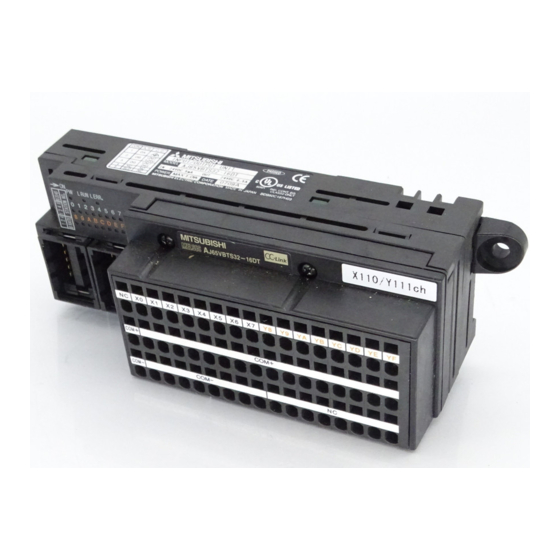
AJ65VBTS32-16DT 形 CC-Link システム小形タイプリモート I/O ユニットユーザーズマニュアル
AJ65VBTS32-16DT CC-Link System Compact Type Remote I/O Module User's Manual
● 安全上のご注意 ●
(ご使用前に必ずお読みください)
本製品のご使用に際しては,本マニュアルをよくお読みいただくと共に,
安全に対して十分に注意を払って,正しい取扱いをしていただくようお願い
いたします。
なお,この注意事項は本製品に関するもののみについて記載したものです。
シーケンサシステムとしての安全上のご注意に関しては, CPUユニットのユー
ザーズマニュアルを参照してください。
この●安全上のご注意●では,安全注意事項のランクを「危険」,「注意」
として区分してあります。
取扱いを誤った場合に,危険な状況が起こりえて,
危 険
死亡または重傷を受ける可能性が想定される場合。
取扱いを誤った場合に,危険な状況が起こりえて,
注 意
中程度の傷害や軽傷を受ける可能性が想定される場
合および物的損害だけの発生が想定される場合。
なお,
注意に記載した事項でも,状況によっては重大な結果に結びつく
可能性があります。
いずれも重要な内容を記載していますので必ず守ってください。
本マニュアルは必要なときに読めるように大切に保管すると共に,必ず最
終ユーザまでお届けいただくようにお願いいたします。
【設計上の注意事項】
● データリンクが交信異常になったとき,交信異常局は次のような状態になります。
交信状態情報を使って, システムが安全側に働くようにシーケンスプログラム上
でインタロック回路を構成してください。誤出力,誤動作により事故の恐れがあ
ります。
(1) リモートI/O局からの入力は,全点OFFします。
(2) リモートI/O局からの出力は,全点OFFします。
● リモートI/Oユニットの故障によっては, 入出力がON状態またはOFF状態になるこ
とがあります。重大な事故につながるような入出力信号については,外部で監視
する回路を設けてください。
● ユニットは,CPUユニットユーザーズマニュアル記載の一般仕様の環境で使用し
てください。
一般仕様の範囲以外の環境で使用すると,感電,火災,誤動作,製品の損傷ある
いは劣化の原因になります。
● 制御線や通信ケーブルは,主回路や動力線などと束線したり,近接したりしない
でください。100mm以上を目安として離してください。
ノイズにより,誤動作の原因になります。
【取付け上の注意事項】
● ユニットの導電部分には直接触らないでください。
ユニットの誤動作,故障の原因になります。
● ユニットは,DINレールなどにて,確実に固定してください。
ユニットを確実に固定しないと,落下,誤動作の原因になります。
● 各接続ケーブルのコネクタは装着部に確実に装着してください。
接触不良による誤動作の原因になります。
【配線上の注意事項】
● 配線作業などは, 必ずシステムで使用している外部供給電源を全相遮断してから
行ってください。 全相遮断しないと, 感電あるいは製品の損傷の恐れがあります。
● FG端子はシーケンサ専用のD種接地(第三種接地)以上で必ず接地を行ってくだ
さい。感電,誤動作の恐れがあります。
● ユニットの配線は, 製品の定格電圧および端子配列を確認した上で正しく行って
ください。定格と異なった電源を接続したり,誤配線すると,火災,故障の原因
になります。
● ユニット内に,切粉や配線クズなどの異物が入らないように注意してください。
火災,故障,誤動作の原因になります。
● ユニットに接続する電線やケーブルは,必ずダクトに納める,またはクランプに
よる固定処理を行ってください。ケーブルをダクトに納めなかったり,クランプ
による固定処理をしていないと,ケーブルのふらつきや移動,不注意の引っ張り
などによるユニットやケーブルの破損, ケーブルの接触不良による誤動作の原因
となります。
● 制御線と通信ケーブルは束線したり,近接したりしないでください。
ノイズにより,誤動作の原因になります。
● ユニットに接続された通信ケーブルや電源ケーブルを取り外すときは, ケーブル
部分を手に持って引っ張らないでください。
コネクタ付きのケーブルは, ユニットに接続している部分のコネクタを手で持っ
て取り外してください。コネクタなしのケーブルは,ユニットに接続している部
分のネジを緩めてから取り外してください。
ユニットに接続された状態でケーブルを引っ張ると,ユニットやケーブルの破
損,ケーブルの接続不良による誤動作の原因となります。
【立上げ・保守時の注意事項】
● 通電中に端子やコネクタに触れないでください。感電の原因になります。
● 清掃,端子ネジ,ユニット取付けネジの増し締めは, 必ずシステムで使用している
外部供給電源を全相遮断してから行ってください。全相遮断しないと,ユニット
の故障や誤動作の原因になります。
危 険
注 意
注 意
危 険
注 意
危 険
本マニュアルは再生紙を使用しています。
● SAFETY PRECAUTIONS ●
(Read these precautions before using.)
When using this equipment, thoroughly read this manual. Also pay careful
attention to safety and handle the module properly.
These precautions apply only to this equipment. Refer to the CPU module
user's manual for a description of the PC system safety precautions.
These ●SAFETY PRECAUTIONS● classify the safety precautions into two
categories: "DANGER" and "CAUTION".
Procedures which may lead to a dangerous
DANGER
condition and cause death or serious injury if not
carried out properly.
Procedures which may lead to a dangerous
CAUTION
condition and cause superficial to medium injury,
or physical damage only, if not carried out properly.
Depending on circumstances, procedures indicated by
also result in to serious results.
In any case, it is important to follow the directions for usage.
Store this manual in a safe place so that you can take it out and read it
whenever necessary. Always forward it to the end user.
【DESIGN PRECAUTIONS】
When a communication error occurs in the data link, the communication error
station will be in the following condition. Configure an interlocking circuit in a
sequence program using the communication status information so that the safety
of the overall system is always maintained.
Accident may occur due to output error or malfunction.
(1) Input points from remote I/O station will be all switched off.
(2) Output points from remote I/O station will be all switched off.
Input/output could be switched on or off when a problem occurs in the remote I/O
modules. So build an external monitoring circuit that will monitor any I/O signals
that could cause a serious accident.
Use each module in an environment as specified in the "general specification" in
the CPU module user's manual. Usage of the module outside the general
Specification range may cause electric shock, fire, malfunction, product damage or
deterioration.
Do not have control cables and communication cables bundled with or placed
near by the main circuit and/or power cables. Wire those cables at least
100mm(3.94 inch) away from the main circuit and/or power cables. It may cause
malfunction due to noise interference.
【INSTALLATION PRECAUTIONS】
Do not directly touch the module's conductive parts.
Doing so could cause malfunction or trouble in the module.
Use a DIN rail or similar to securely fix the module. If the module is not securely
fixed, it may fall off or cause malfunction.
Correctly connect the cable connectors to the loading positions.
A poor connection could result in erroneous operation.
【WIRING PRECAUTIONS】
Completely turn off the externally supplied power used in the system when
installing or placing wiring. Not completely turning off all power could result in
electric shock or damage to the product.
Always ground the FG terminal. There is a risk of electric shock or malfunction.
Perform correct wiring for the module according to the product's rated voltage and
terminal arrangement. Connecting to a power supply different from rating or
miss-wiring may cause fire and/or product failure.
Make sure foreign objects do not get inside the module, such as dirt and wire
chips. It may cause fire, product failure or malfunction.
Be sure to fix the wires or cables by ducts or clamps when connecting them to the
module. Failure to do so may cause damage of the module or the cables due to
accidental pull or unintentional shifting of the cables, or malfunctions due to poor
contact of the cable.
Do not install the control lines together with the communication cables, or bring
them close to each other. Failure to do so may cause malfunctions due to noise.
Do not pull the cable part by hand when removing a communication cable and
power supply cable from a module.
For a cable with connector, remove it while holding the connector by hand.
For a cable with no connector, loosen the screw securing the cable to the module
and then remove it.
Pulling a cable with connected to the module may damage the module or cable, or
result in malfunction due to cable poor connection.
【STARTING AND MAINTENANCE PRECAUTIONS】
Do not touch terminals or connectors when the power is on. Doing so could cause
an electric shock.
Switch off all phases of the externally supplied power used in the system when
cleaning the module or retightening the terminal or module mounting screws. Not
doing so could result in electric shock.
IB 番号
IB-0800272-E
IB No.
形名
AJ65VBTS32-16DT-U
Model
CAUTION may
(0705) MEE
DANGER
CAUTION
CAUTION
DANGER
CAUTION
DANGER
Printed in Japan on recycled paper.
Advertisement
Table of Contents

Related Manuals for Mitsubishi Electric AJ65VBTS32-16DT


Summary of Contents for Mitsubishi Electric AJ65VBTS32-16DT
- Page 1 IB No. 形名 AJ65VBTS32-16DT-U Model AJ65VBTS32-16DT 形 CC-Link システム小形タイプリモート I/O ユニットユーザーズマニュアル AJ65VBTS32-16DT CC-Link System Compact Type Remote I/O Module User’s Manual ● SAFETY PRECAUTIONS ● ● 安全上のご注意 ● (ご使用前に必ずお読みください) (Read these precautions before using.) When using this equipment, thoroughly read this manual. Also pay careful 本製品のご使用に際しては,本マニュアルをよくお読みいただくと共に,...
- Page 2 [Applicable wire size: 0.9 to 1.0 mm TE1.5((株)ニチフ) TE1.5 (NICHIFU Co., ltd) [適合電線サイズ:1.25~1.5mm [Applicable wire size: 1.25 to 1.5 mm FA-VTC125T9(三菱電機エンジニアリング(株)) FA-VTC125T9 (MITSUBISHI ELECTRIC [適合電線サイズ:0.3~1.65mm ENGINEERING CO., LTD) FA-VTCW125T9(三菱電機エンジニアリング(株)) [Applicable wire size: 0.3 to 1.65 mm [適合電線サイズ:0.3~1.65mm FA-VTCW125T9 (MITSUBISHI ELECTRIC ENGINEERING CO., LTD)
- Page 3 外部接続 (External connection) ピン番号 Pin No. 信号名 Signal name CONA CON A, B LINK CABLE Empty (IN) Empty (FG) CONB +24V (UNIT) CON C, D 24G (UNIT) LINK CABLE (OUT) Empty Empty Empty 端子台 Terminal block 通信用ワンタッチコネクタ One-touch connector for communication A 列...
- Page 4 2-M4取付ネジ穴 2-M4 installation screw hole 15.5 (5.39) (0.61) 106±0.5 *1 (0.20) (4.17±0.02) *1 ① ⑨ ⑥ L RUN L ERR. AJ65VBTS32-16DT ③ X2 X3 YA YB YC YD YE DINレール中心 ② ⑧ COM+ COM+ DIN rail center (0.16) COM- COM- ⑧...
Need help?
Do you have a question about the AJ65VBTS32-16DT and is the answer not in the manual?
Questions and answers