Table of Contents
Advertisement
Quick Links
SERVICE MANUAL
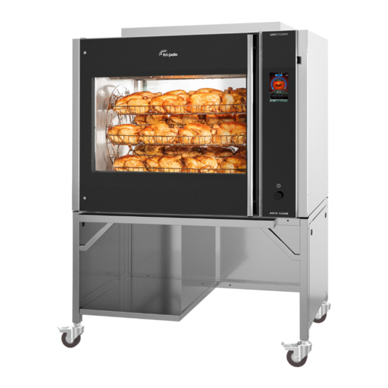
LDR 8 s Auto-Clean Gas
MODELS
LDR 8s AC Gas
This manual is prepared for the use of trained Service Technicians and should not be used by
This manual is not intended to be all encompassing. If you have not attended a training for
Reproduction or other use of this Manual, without the express written consent of Fri-Jado, is
Service Manual LDR 8s AC
those not properly qualified. If you have attended a training for this product, you may be
qualified to perform all the procedures in this manual.
this product, you should read, in its entirety, the repair procedure you wish to perform to
determine if you have the necessary tools, instruments and skills required to perform the
procedure. Procedures for which you do not have the necessary tools, instruments and
skills should be performed by a trained technician.
form 9120934 rev. 02/2022
II
- NOTICE -
prohibited.
WWW.FRIJADO.COM
Advertisement
Table of Contents
Troubleshooting

Related Manuals for Fri-Jado LDR 8s AC Gas


Summary of Contents for Fri-Jado LDR 8s AC Gas
- Page 1 Procedures for which you do not have the necessary tools, instruments and skills should be performed by a trained technician. Reproduction or other use of this Manual, without the express written consent of Fri-Jado, is prohibited. Service Manual LDR 8s AC form 9120934 rev.
- Page 2 TABLE OF CONTENTS Service Manual LDR 8s AC form 9120934 rev. 02/2022 Page 2 PKII...
-
Page 3: Table Of Contents
20220210 10-02-2022 First release INDEX Index ................................3 LDR 8s ac Installation ..........................6 LDR 8s AC Gas, technical data....................... 6 Required tools ............................7 Introduction ............................. 8 Unpacking the unit ..........................8 Location ..............................10 Electrical supply ............................ 10 Legs / Castors ............................11... - Page 4 LDR 8s AC gas, Partslist Rotor ......................71 LDR 8s AC gas, Blower & Heating ......................72 LDR 8s AC gas, Partslist Blower & Heating ..................73 LDR 8s AC gas, Cleaning system ......................74 LDR 8s AC gas, Partslist Cleaning system ................... 75 LDR 8s AC gas, Sheet metal ........................
- Page 5 TABLE OF CONTENTS LDR 8s AC gas, Underframe ......................... 78 LDR 8s AC gas, Partslist Underframe ....................79 Fasteners .............................. 80 Electrical diagrams..........................82 Circuit diagram LDR 8s ac ........................82 Wiring diagram LDR 8s ac ........................83 Overview of I/O board with interface board ................... 84 Service Manual LDR 8s AC form 9120934 rev.
-
Page 6: Ldr 8S Ac Installation
LDR 8S AC INSTALLATION LDR 8S AC GAS, TECHNICAL DATA Consult the identification plate to get the proper specifications of the rotisserie. The electrical data may vary from country to country. All of the information, illustrations and specifications contained in this manual are based on the latest product information available at the time of printing. -
Page 7: Required Tools
LDR 8s ac Installation REQUIRED TOOLS For proper installation Fri-Jado recommend having the following list of tools available during installation: • Standard set of tools. • Metric wrenches, sockets and hex socket key wrenches. • Multi-meter. • AC current clamp tester. -
Page 8: Introduction
LDR 8s ac Installation INTRODUCTION • Unpacking of the unit. • Remove the pallet under the unit with the help of a fork lift. • Put the unit on his location. • Check if there is enough free space around the unit (see installation drawing). •... - Page 9 LDR 8s ac Installation Remove screws (front 4x and back 4x) Cut straps, remove box and tempex. Fasten the ramps ! Fasten the ramps ! Keep locked ! Keep locked ! Place the ramps in front of the pallet Tilt the unit slightly and remove the front beam. and fasten them.
-
Page 10: Location
LDR 8s ac Installation LOCATION The oven must be installed on a level surface. The installation location must allow adequate clearances for servicing and proper operation. The oven must be protected against falling moisture ! The ambient temperature of the rotisserie must be between 10 and 30 °C (50 and 86 °F). -
Page 11: Legs / Castors
LDR 8s ac Installation LEGS / CASTORS The LDR 8s AC is placed on a stand with 4 locking swivel castors. TETHERING OF THE UNIT Warning: Safety standards require that, when this appliance is properly connected to the electrical power supply using flexible conduit, adequate means be provided to limit movement of the ap- pliance without depending on or transmitting stress to the electrical conduit. -
Page 12: Power, Water And Drain Connections Ldr 8S Ac
LDR 8s ac Installation POWER, WATER AND DRAIN CONNECTIONS LDR 8S AC The Power (electric and gas), water and drain connections can be found below the con- troller side of the unit. See the labels 1 untill 5 208V Mains cable 75” with Nema 6-15P Plug Gas supply connection 1/2”... -
Page 13: Water Requirements
LDR 8s ac Installation WATER REQUIREMENTS The supplied tap water must have the following conditions: 1. Minimum pressure 200 kPa (2 bar) 2. Maximum pressure 500 kPa (5 bar) 3. Maximum water temperature 55 °C (130 °F) 4. Acidity pH 7.0 - 8.0 5. -
Page 14: Gas Connection
LDR 8s ac Installation GAS CONNECTION 1. All gas supply connections and any pipe joint compound used must be resistant to the action of propane gases. Codes require a gas shutoff valve be installed in the gas line ahead of the rotisserie. -
Page 15: Gas Pressure
LDR 8s ac Installation GAS PRESSURE The gas inlet pressure has to be according to the table on the technical data page. (Chapter 1) The pressure can be checked on the gas block with a pressure meter like in the picture below. Gas inlet: Inlet of gas after gas pressure reduction valve (max. -
Page 16: Flue Gas Analyser
LDR 8s ac Installation FLUE GAS ANALYSER 1. With the flue gas analyzer you can measure the exhaust gas on the rotisserie for toxicity. With the use of a Testo 330-1LL you get the following measurements: Values below are references and factory defaults. RPM [min-1] CO2 [%] Power Hs in [kW]... -
Page 17: Connecting The Drain Tube
LDR 8s ac Installation CONNECTING THE DRAIN TUBE An open draining system with a 110 mm (4 1/2”) funnel is recommended. The drain tube has an outside diameter of 33 mm (1 5/16”). • It is not allowed to make a closed connection! •... -
Page 18: Grease Collection
LDR 8s ac Installation GREASE COLLECTION Place the bucket, which is delivered with the unit, inside the stand under the drain pipe. It is also possible to put other containers in the underframe to collect the grease. Note 1: In one run, 6 liters (1.5 gallon) grease can come out. Note 2: The temperature of the grease can go up to 80 °C (176 °F). -
Page 19: Ldr 8S Ac On Stand
LDR 8s ac Installation LDR 8S AC ON STAND >100 (4”) 1845 (72 5/8”) >50 (2”) Location of mains connection Location of gas supply connection 1/2” NPT Location of water connectionG 3/4” BSP Location of drain hose OD Ø 33 mm (1 1/16”) Location of fat drain Minimum required space Example of funnel... -
Page 20: Software "S" Controller (Touch Screen)
SOFTWARE “S” CONTROLLER (TOUCH SCREEN) SWITCHING ON Main functions Other symbols Touch the screen somewhere Language Pause Home screen Extra time ON / OFF or stop program Continue Recipes menu Create recipe Home screen Edit recipe Touch the ON / Cleaning program OFF symbol Confirm... -
Page 21: Running A Cooking Program
SOFTWARE RUNNING A COOKING PROGRAM Push recipes icon Choose program Check fat container and Start program push “continue” Ricette Change fat container Cancel Continu The below 4 steps are only applicable in case the cooking program has a pre-heat step. Preheat starts. -
Page 22: Creating A Cooking Program
SOFTWARE CREATING A COOKING PROGRAM Chose product icon and fill in recipe name. Push recipes icon Push icon Chose or change step name if applicable. Drag up for an extra cooking step. Chicken Create Recipe My Recipe Other name if applicable Preriscaldamento Grigliare Cuocere... -
Page 23: Example Of Error Message
SOFTWARE EXAMPLE OF ERROR MESSAGE In the “log” menu the er- Select the error Example motor failure Meta data is shown during cooking. ror can be found Motor failure In manager menu: Go to the manager menu to clear the error. Scroll to “Clear errors”... -
Page 24: The Cleaning Program
SOFTWARE THE CLEANING PROGRAM Push cleaning icon Choose program If unit is too hot, it will Now it is asked to place cool down first. the detergent. Follow the instructions that can be found in the container with detergent. Place the detergent. Push to pause, if appli- Cleaning program has... -
Page 25: Cleaning Process Tdrac (3 Cycles)
SOFTWARE CLEANING PROCESS TDRAC (3 CYCLES) Parameter setting Operator action / delay Proces stage Proces cycle Service Manual LDR 8s AC form 9120934 rev. 02/2022 Page 25... -
Page 26: Pump And Valves In Action During Cleaning
SOFTWARE PUMP AND VALVES IN ACTION DURING CLEANING Valve position during cooking cooking cooking The pictures below show each stage in the cleaning pro- gram. -Tubes in red, are flowing -PumpS or valves in yellow are active / open. -Soap has to be added after stage 1 -The first cycle is following stage 1 untill 10. - Page 27 SOFTWARE The stage 3 and 4 are rehearsing alternately, during 1 minute each, over a period of 20 minutes, with the heating on and after that, during 10 minutes with the heating off. The third cycle has only heating on. In case of a sanitation step, that will be like stage 10, but then only with the heating on.
-
Page 28: I/O Test
SOFTWARE I/O TEST Gain access to the service menu 4878 Select “I/O test” “Analog input” shows PT1000 temperature (in 0,1 degrees) Example below is 67°C “Digital inputs” is showing the available inputs and also which contacts are closed. The picture shows the all good situation J13 Door is closed. -
Page 29: Exchanging Data With The Usb Drive
SOFTWARE EXCHANGING DATA WITH THE USB DRIVE The password for service is 4878. Once the service menu is entered, also the manager menu is unlocked. Copies recipes from the controller to the USB drive Copies recipes from the USB drive to the con- troller. - Page 30 SOFTWARE Device Con- BROWN nec- WHITE R1 -> J2-4 WHITE/A M1 Rotor J2-4 Rotor motor R3 -> J2-3 P1 / P2 M2 Blower J2-3 Blower Q3 / K6 R2 -> J2-1 K1 Heater J2-1 Heating K1 Heating Rd Ye Bu J8-2 J8-1 J13-2...
-
Page 31: Updating Software Ldr Ac (S-Control)
SOFTWARE UPDATING SOFTWARE LDR AC (S-CONTROL) Preparing the software (firmware) 4. The following messages appear Bootloader version V4.03.04 The software comes in a .zip file. The name cor- -USB stick found responds with the version of the software. For starting upgrade example: V1_00_3.zip. -
Page 32: Automatic Cook Correction
SOFTWARE AUTOMATIC COOK CORRECTION The automatic cook correction facility will automaticly add or deduct time to the pro- grammed cooking time in order to have constant cooking quality. To activate it, the parameter “auto correct” has to be put on “time”. Go to the manager menu -->... -
Page 33: Default Parameters Version 1.00.34 Ldr 8S-Ac 208V
SOFTWARE DEFAULT PARAMETERS VERSION 1.00.34 LDR 8S-AC 208V About / software version 1.00.34 Manager Change Pin code 0000 - 9999 Toggle Light on - off Temperature unit °F °C - °F Volume unit filter liters liters-gallon UTC time Local time UTC date Actual date Time zone offset... - Page 34 SOFTWARE Drain time 2-40 min Supply time 1 1-120 sec demo clean start no-yes auto off time 60 min no or 10 - 240 change pin **** read out of the manager pin code Drain duration 40 sec. 10 -40 Fat drain open open - programmed...
- Page 35 SOFTWARE I/O test Analog input Digital inputs read the inputs and set the outputs Digital outputs read the inputs and set the outputs Board Feed- read the inputs and set the outputs back Board Version read the inputs and set the outputs Board Variant read the inputs and set the outputs Test program...
- Page 36 SOFTWARE Reset blower time no - yes Rotor Reset rotor time no - yes Light Reset light time no - yes Pump Reset Pump time no - yes Start/End Counters #started recipes #ended recipes #started quick clear #ended quick clean #started daily clean #ended daily clean #started full descale...
-
Page 37: Explanation Of Parameters
SOFTWARE EXPLANATION OF PARAMETERS Level 1 Level 2 Level 3 Change Pin code Option to change the manager pin code Toggle Light Option to switch on or off the interior light. Temperature unit Change the temperature units from Fahrenheit to Celcius or from Clecius to Fahrenheit. Volume unit filter Change the volulme units from Liters to Gallon or from Gallon to Liters. - Page 38 SOFTWARE Level 1 Level 2 Level 3 language Option to select the desired language Eco variable Option to set the influence of the Eco mode save errors Option to save the error log/history to a USB key. clear error history Option to clear the error log/history RS485 debugging Option to activate or deactivate the RS485 debugging...
- Page 39 Wifi Smartphone Optin to allow a connection to an Smartphone Wifi smart Cloud Option to enable a connection to the Fri-Jado Smart Connect website. Wifi RSSI Shows the signal level of the WiFi connection. Values are between -101dBm and -1dBm. In practice values are between -85dBm and -25dBm.
- Page 40 SOFTWARE Level 1 Level 2 Level 3 Fact reset recipes Reset to factory recipes Fact reset data Reset of factory data Commision reset Reset of set commission date Commission apply Option to apply the current date/time for commissioning Customer ID By entering the a maching customer code the correct story boards and explanations are given in the help function Restart soft...
-
Page 41: Electrical Tests
ELECTRICAL TESTS MEASURING THE BLOWER MOTOR WARNING: Disconnect the electrical power to the machine at the main circuit box. Place a tag on the circuit box indicating the circuit is being serviced. Blower of rotisserie ∞ Ω Blue PH1 208/240V 50/60Hz 1,8A White 5uF 400V Thermally protected 500V... -
Page 42: Measuring The 160W Lamp
ELECTRICAL TESTS The 6µF capacitor General >50 MΩ Even with a capacitance meter it is impossible to 6 µF Insulation test determine for sure if the capacitor is ok or not, because it can be leaking when it is connected to 500V mains power. -
Page 43: Measuring The Rotor (Drive) Motor
ELECTRICAL TESTS MEASURING THE ROTOR (DRIVE) MOTOR White 120 Ω Brown 240 Ω 120 Ω White (A) ∞ MΩ 500V MEASURING THE PT1000 SENSOR The oven temperature is controlled by a PT1000 sensor, mounted in the top at the side. See the resistance overview for the PT1000 sensors. -
Page 44: Measuring The Motor Valve
ELECTRICAL TESTS MEASURING THE MOTOR VALVE >1MΩ >1MΩ >1MΩ Valve position. closed in this view 24V= Pull to open manual. Ccw = open Cw= close 24V= 24V= MEASURING THE PUMP 2 Amp. at free run 5-6 Amp. at full load 0 Ω... -
Page 45: Service Procedures
SERVICE PROCEDURES WARNING: Disconnect the electrical power to the machine at the main circuit box. Place a tag on the circuit box indicating the circuit is being serviced. ACCESS TO SERVICE PARTS LDR 8S AC Side view Unscrew 4 screws and open the panel from the electric compartment . - Page 46 SERVICE PROCEDURES Top view with removed top panel 23. Blower motor. 24. Hi limit sensor. 25. PT1000 sensor. 26. Illumination. 27. Heat exchanger. 28. Turbine. Inside view with removed blower panel Service Manual LDR 8s AC form 9120934 rev. 02/2022 Page 46 PKII...
-
Page 47: Blower Motor
SERVICE PROCEDURES BLOWER MOTOR Dismounting the blower assembly. 1. Remove both side panels and the top pa- 2. Remove the blower panel 3. Remove the M5 nut and washer from the motor shaft 4. Pull the turbine from the shaft. A puller is delivered with the new blower kit. -
Page 48: Rotor Drive Motor
SERVICE PROCEDURES ROTOR DRIVE MOTOR Dismounting the rotor motor: Note, #4 and #5 are applicable from serial number 100075954. 1. Remove the side panel at the operator- panel side. 2. Mark the position of the motor on the bracket. 3. Take the rotor shaft out of the cooking cavity. - Page 49 SERVICE PROCEDURES Centering of Mounting the rotor motor shaft in hole 1. Mount the motor on the bracket using the previous made mark (see #2 from disassembling). 2. The motor shaft should come through the center of the hole!! 3. Connect the wiring of the (new) motor. See previous page for position of wires.
- Page 50 SERVICE PROCEDURES Service Manual LDR 8s AC form 9120934 rev. 02/2022 Page 50 PKII...
-
Page 51: Trouble Shooting
TROUBLE SHOOTING OVERVIEW OF ERROR CODES TDRAC. Error message Description Possible causes Top sensor open (i) The temperature sensor input Wiring loose Sensor overflow (s) reads higher than 320°C (600°F). Broken sensor Broken I/O board In resistance, this is higher than 2200Ω. -
Page 52: Trouble Shooting By Symptom
TROUBLE SHOOTING TROUBLE SHOOTING BY SYMPTOM. Symptom Possible cause Caused by Unit will not switch on. Power disconnected Power plug disconnected Mains switch in OFF position. Mains breaker open Short circuit or insulation problem Fuse(s) blown Power surge Check fuse(s) on the electric panel Wiring problem Wiring loose of plugs or sockets inside and out- side of unit. - Page 53 TROUBLE SHOOTING Symptom Possible cause Caused by Beep functions missing Buzzer / speaker not func- Loose connection tioning Broken buzzer / speaker Parameter “key beep” switch off Mains fuse or breaker Short circuit or insulation Mains plug burned, or wet switched off problem Heating element broken...
- Page 54 TROUBLE SHOOTING Symptom Possible cause Caused by Bad cleaning result. Water issue Water tap closed Check parameter settings! Descale filter saturated No descaling filter applied while the water hardness is high Detergent issue Cleaning cartridge not placed on the right place Wrong (amount) detergent Drain issue Sewer drain malfunction (Q5)
-
Page 55: Trouble Shooting By Part / Function
TROUBLE SHOOTING TROUBLE SHOOTING BY PART / FUNCTION. Descrip- Symptoms Possible cause Action tion of part / function Inside door Broken glass Slamming of door. Give instruction to operator. Fastening bolts and nuts Tighten all fastenings. are loose. No PTFE ring between Mount new door. - Page 56 TROUBLE SHOOTING Descrip- Symptoms Possible cause Action tion of part / function Drive motor Motor doesn’t Wiring. Check the wiring. Check the power to the motor. Coil malfunction. Check insulation value of coil with Megger and / or on 500V. Minimum value is 0.5 MΩ. main fuse burned Check resistance of the coils.
- Page 57 TROUBLE SHOOTING Descrip- Symptoms Possible cause Action tion of part / function PT-sensor Temperature Resistance of sensor lower, Replace sensor inside rotisserie caused by moist inside higher than set Short circuit in sensor. Replace sensor temperature Sensor not in right positi- Check / adjust position of sensor on.
- Page 58 TROUBLE SHOOTING Descrip- Symptoms Possible cause Action tion of part / function Pump Not pumping Suction valve Q1 Check the valve if it is closed while the wa- (9311008s) malfunctio- terinlet valve is opened and the unit is being See below over- ning filled.
-
Page 59: Hydraulic Overview
TROUBLE SHOOTING HYDRAULIC OVERVIEW Suction filter Descaling filter By-pass on zero!! Service Manual LDR 8s AC form 9120934 rev. 02/2022 Page 59 Page 59... -
Page 60: Exploded Views And Partslists
EXPLODED VIEWS AND PARTSLISTS LDR 8S AC GAS, ELECTRICAL PARTS 6µF 6µF 55 54 36 43 36 39 32 42 Service Manual LDR 8s AC form 9120934 rev. 02/2022 Page 60 PKII... -
Page 61: Ldr 8S Ac Gas, Partslist Electrical Parts
EXPLODED VIEWS AND PARTSLISTS LDR 8S AC GAS, PARTSLIST ELECTRICAL PARTS Part nr. Description Comment 9292280s CPU + LCD board s-control 9292282s CPU + LCD board s-control (without WIFI) 9311046s Speaker 9172314 Ribbon cable 14p 9192400s Power & I/O board... -
Page 62: Ldr 8S Ac Gas, Electrical Parts
EXPLODED VIEWS AND PARTSLISTS LDR 8S AC GAS, ELECTRICAL PARTS 1050 mm (41 1/4”) 950 mm (37 3/8”) 9310852s <--1 <--2 <--3 <--4 <--5 <--6 Service Manual LDR 8s AC form 9120934 rev. 02/2022 Page 62 PKII... -
Page 63: Ldr 8S Ac Gas, Partslist Electrical Parts
EXPLODED VIEWS AND PARTSLISTS LDR 8S AC GAS, PARTSLIST ELECTRICAL PARTS Pos Part nr. Description Priority Comment 9291176 Crimp contact, inputs 9291175 Socket, 2 p, inputs 9291177 Socket, 3 p, inputs 9310850s Wire repair set inputs 3701231 Crimp contact, outputs... -
Page 64: Ldr 8S Ac Gas, Control Panels
EXPLODED VIEWS AND PARTSLISTS LDR 8S AC GAS, CONTROL PANELS Service Manual LDR 8s AC form 9120934 rev. 02/2022 Page 64 PKII... -
Page 65: Ldr 8S Ac Gas, Partslist Control Panels
EXPLODED VIEWS AND PARTSLISTS LDR 8S AC GAS, PARTSLIST CONTROL PANELS Pos Part nr. Description Priority Comment 9292280s CPU + LCD board s-control 9292282s CPU + LCD board s-control (without WIFI) 9311046s Speaker 9310161 USB socket, ass. 9311047 Cable, speaker s-control... -
Page 66: Ldr 8S Ac Gas, Doors
EXPLODED VIEWS AND PARTSLISTS LDR 8S AC GAS, DOORS (3x) (3x) Service Manual LDR 8s AC form 9120934 rev. 02/2022 Page 66 PKII... -
Page 67: Ldr 8S Ac Gas, Doors
EXPLODED VIEWS AND PARTSLISTS LDR 8S AC GAS, DOORS Pos Part nr. Description Priority Comment 9348510s Ass. Outer door Left turning LDR8s AC 9348512s Ass. Outer door Right turning LDR8s AC 9348513s Ass. Inner door Left turning LDR8s AC 9348511s Ass. -
Page 68: Ldr 8S Ac Gas, Lighting And Sensors
EXPLODED VIEWS AND PARTSLISTS LDR 8S AC GAS, LIGHTING AND SENSORS Service Manual LDR 8s AC form 9120934 rev. 02/2022 Page 68 PKII... -
Page 69: Ldr 8S Ac Gas, Lighting And Sensors
EXPLODED VIEWS AND PARTSLISTS LDR 8S AC GAS, LIGHTING AND SENSORS Pos Part nr. Description Priority Comment 9040970 Thermostat 122-608° 9351020s Lamp 160W 9311015 Lamp holder R7s ceramic 9172310s Temperature sensor PT 1000 9314113 Cover, lamp 9314114 Mounting bracket, lamp fixture. -
Page 70: Ldr 8S Ac Gas Rotor
EXPLODED VIEWS AND PARTSLISTS LDR 8S AC GAS ROTOR Service Manual LDR 8s AC form 9120934 rev. 02/2022 Page 70 PKII... -
Page 71: Ldr 8S Ac Gas, Partslist Rotor
EXPLODED VIEWS AND PARTSLISTS LDR 8S AC GAS, PARTSLIST ROTOR Pos Part nr. Description Priority Comment 9340105s Gearmotor, complete with drive head Ass. Rotor LDR8 ac 9340416 Rotor shaft 9314220 Rotor disk 9302027 Support pin, meat baskets 9310180s Bearing ass., rotor TDR7/8ac... -
Page 72: Ldr 8S Ac Gas, Blower & Heating
EXPLODED VIEWS AND PARTSLISTS LDR 8S AC GAS, BLOWER & HEATING 279 (26 + 272 + 273 + 274) 273 275 Service Manual LDR 8s AC form 9120934 rev. 02/2022 Page 72 PKII... -
Page 73: Ldr 8S Ac Gas, Partslist Blower & Heating
EXPLODED VIEWS AND PARTSLISTS LDR 8S AC GAS, PARTSLIST BLOWER & HEATING Pos Part nr. Description Priority Comment 9292113s Ignition set, gasket included 9221075 Gasmixture blower 9291022s Gas valve Burner safety controller, G20 natural gas 9291111 Pressure switch Blower, ass. TDR 8s ac gas... -
Page 74: Ldr 8S Ac Gas, Cleaning System
EXPLODED VIEWS AND PARTSLISTS LDR 8S AC GAS, CLEANING SYSTEM Service Manual LDR 8s AC form 9120934 rev. 02/2022 Page 74 PKII... -
Page 75: Ldr 8S Ac Gas, Partslist Cleaning System
EXPLODED VIEWS AND PARTSLISTS LDR 8S AC GAS, PARTSLIST CLEANING SYSTEM Pos Part nr. Description Pri- ority 9311006s Pump 9311008s Motor valve -2/2 1/2" CR03 9311007s Solenoïd valve E 2/2 - 1/2" (reduced 9 ltr/min) 9311013s Motor valve -2/2 3/4" CR03... -
Page 76: Ldr 8S Ac Gas, Sheet Metal
EXPLODED VIEWS AND PARTSLISTS LDR 8S AC GAS, SHEET METAL Service Manual LDR 8s AC form 9120934 rev. 02/2022 Page 76 PKII... -
Page 77: Ldr 8S Ac Gas, Partslist Sheet Metal
EXPLODED VIEWS AND PARTSLISTS LDR 8S AC GAS, PARTSLIST SHEET METAL Pos Part nr. Description Priority Comment 9344090 Side panel L/R 9344092 Cover, fan 9174485 Drop-in guard, exhaust 9344091 Top panel 9344018 Reinforcement R top 9344017 Reinforcement R 9314166 Magnet profile... -
Page 78: Ldr 8S Ac Gas, Underframe
EXPLODED VIEWS AND PARTSLISTS LDR 8S AC GAS, UNDERFRAME Service Manual LDR 8s AC form 9120934 rev. 02/2022 Page 78 PKII... -
Page 79: Ldr 8S Ac Gas, Partslist Underframe
EXPLODED VIEWS AND PARTSLISTS LDR 8S AC GAS, PARTSLIST UNDERFRAME Pos Part nr. Description Priority Comment 9314603s Side panel L, ass. 9344114s Rear panel, ass. 9344603s Side panel R ass. 9344117 Panel, box 9340430 Casco 9344108 Driptray 9314604 Spring 9190177... -
Page 80: Fasteners
EXPLODED VIEWS AND PARTSLISTS FASTENERS Pos Part nr Pos Part nr Description Description 800 4280107 Bolt M6x20 ZP 864 4285319 Screw 4,8x13, ZP Self drilling and tapping. 801 4289559 Lockwasher M6, serrated ZP 866 4287620 Screw 4,2x12, NP self tapping 802 4288321 Screw M5x16, SS socket button head. - Page 81 EXPLODED VIEWS AND PARTSLISTS Pos Part nr Description Pos Part nr Description 978 0211521 Screw M5x16, SS hex. Head 929 0197378 Washer M12, Zp 930 9008056 Nut M12, ZP 979 4285041 Lock nut M5, SS 980 4280181 Screw M8x60, hexagon 931 0142056 Lockwasher M8, SS 981 4280187...
-
Page 82: Electrical Diagrams
ELECTRICAL DIAGRAMS ELECTRICAL DIAGRAMS CIRCUIT DIAGRAM LDR 8S AC J8-2 PT-1000 J8-1 RELAY RESET GAS J13-2 Door switch J13-1 PUMP SUPPLY J14-2 FANcontrol RINSE LEFT J14-1 GREASE DRAIN J17-2 ERROR J17-1 CASCO VALVE SEWER VALVE J12-2 Modulation J12-1 WATER VALVE ROTOR option ROTOR LIGHT... -
Page 83: Wiring Diagram Ldr 8S Ac
ELECTRICAL DIAGRAMS WIRING DIAGRAM LDR 8S AC BLOWERS M4 (115V) Blower RG128 M2.1 M2.2 ~115V WHWH WHWH 44 46 45 79 80 80 81 GY BN WH RD = RED HONEYWELL REGULATOR S4965V 2131 GY = GREY OR = ORANGE House-valve BU = BLUE WH = WHITE... -
Page 84: Overview Of I/O Board With Interface Board
ELECTRICAL DIAGRAMS OVERVIEW OF I/O BOARD WITH INTERFACE BOARD Signal J16-J17 J7-J11 5 Vdc Signal Input connectors J12 J11 F1 = Fuse 1AT 250V J1 = Power socket J1.1 -PE J1.3 -L1 = Led signal J1.5 -N (or L2) Rel. Rel. - Page 85 Service Manual LDR 8s AC form 9120934 rev. 02/2022...
- Page 86 Service Manual LDR 8s AC form 9120934 rev. 02/2022 PKII...
Need help?
Do you have a question about the LDR 8s AC Gas and is the answer not in the manual?
Questions and answers