Goodwe HT Series User Manual
Grid-tied pv inverter
Hide thumbs
Also See for HT Series:
- User manual (60 pages) ,
- Quick installation manual (2 pages) ,
- User manual (19 pages)
Table of Contents
Advertisement
Advertisement
Table of Contents

Related Manuals for Goodwe HT Series


Summary of Contents for Goodwe HT Series
- Page 1 User Manual Grid-Tied PV Inverter HT Series (73-136kW) V1.1-2022-07-20...
- Page 2 GoodWe Technologies Co., Ltd. Trademarks and other GoodWe trademarks are trademarks of GoodWe Company. All other trademarks or registered trademarks mentioned in this manual are owned by GoodWe Technologies Co., Ltd. Notice The information in this user manual is subject to change due to product updates or other reasons.
-
Page 3: Table Of Contents
Content User Manual V1.1-2022-07-20 CONTENT 1 About This Manual ..............1 1.1 Applicable Model ..................1 1.2 Target Audience ....................1 1.3 Symbol Definition ..................2 1.4 Updates ......................2 2 Safety Precaution ..............3 2.1 General Safety ....................3 2.2 DC Side: ......................3 2.3 AC Side ......................4 2.4 Inverter Installation ..................4 2.5 Personal Requirements ................4 3 Product Introduction .............5... - Page 4 User Manual V1.1-2022-07-20 Content 6.3 Connecting the PV Input Cable ..............23 6.4 Connecting the AC Output Cable ............25 6.5 Communication ..................28 6.5.1 Connecting the Communication Cable ............28 6.5.2 Installing the Communication Module (optional) ...........33 7 Equipment Commissioning ..........34 7.1 Check Items Before Switching Power ON ..........34 7.2 Power On .....................34 8 System Commissioning ............35 8.1 Indicators and Button ................35...
-
Page 5: About This Manual
All the installers and users have to be familiar with the product features, functions, and safety precautions. This manual is subject to update without notice. For more product details and latest documents, visit www.goodwe.com. 1.1 Applicable Model... -
Page 6: Symbol Definition
User Manual V1.1-2022-07-20 01 About This Manual 1.3 Symbol Definition Different levels of warning messages in this manual are defined as follows: DANGER Indicates a high-level hazard that, if not avoided, will result in death or serious injury. WARNING Indicates a medium-level hazard that, if not avoided, could result in death or serious injury. CAUTION Indicates a low-level hazard that, if not avoided, could result in minor or moderate injury. -
Page 7: Safety Precaution
• Strictly follow the installation, operation, and configuration instructions in this manual. The manufacturer shall not be liable for equipment damage or personal injury if you do not follow the instructions. For more warranty details, visit https://en.goodwe.com/warranty. asp. 2.2 DC Side: DANGER Connect the DC cables using the delivered DC connectors and terminals. -
Page 8: Ac Side
02 Safety Precaution User Manual V1.1-2022-07-20 2.3 AC Side WARNING • The voltage and frequency at the connecting point should meet the on-grid requirements. • An additional protective device like the circuit breaker or fuse is recommended on the AC side. -
Page 9: Product Introduction
03 Product Introduction User Manual V1.1-2022-07-20 3 Product Introduction 3.1 Application Scenarios The HT inverter is a three-phase PV string grid-tied inverter. The inverter converts the DC power generated by the PV module into AC power and feeds it into the utility grid. The intended use of the inverter is as follows: Circuit Transformer... - Page 10 User Manual V1.1-2022-07-20 03 Product Introduction The circuit diagram of GW73KLV-HT/GW110K-HT/GW120K-HT is as follows. DC Switch MPPT1 MPPT2 MPPT3 DC/AC Inverter Filter Filter Filter Circuit PV10 MPPT10 PV11 MPPT11 PV12 MPPT12 AC SPD Output Current Current DC SPD Disconnecting Monitoring Monitoring Relay The circuit diagram of GW136K-HTH is as follows.
-
Page 11: Supported Grid Types
03 Product Introduction User Manual V1.1-2022-07-20 3.3 Supported Grid Types NOTICE • For the TT grid structure, the effective value of the voltage between the neutral wire and the ground wire must be less than 20V. The grid structures supported by GW73KLV-HT, GW75K-HT, GW80K-HT, GW100K-HT, GW110K-HT, GW120K-HT are TN-S, TN-C,TN-C-S, TT, IT, as shown in the figure below: TN-S TN-C... -
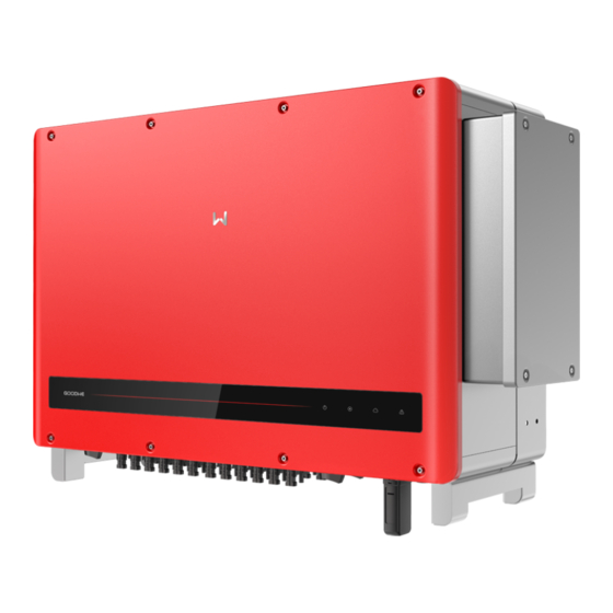
Page 12: Appearance
User Manual V1.1-2022-07-20 03 Product Introduction 3.4 Appearance 3.4.1 Parts... - Page 13 03 Product Introduction User Manual V1.1-2022-07-20 Parts Description DC Switch 1-3 Start or stop 1-3 DC input. PV Input Terminal 1-3 (Controlled by DC Switch Used to connect the PV module DC input cables. 1-3) PV Input Terminal 7-9 (Controlled by DC Switch Used to connect the PV module DC input cables.
-
Page 14: Indicators
User Manual V1.1-2022-07-20 03 Product Introduction 3.4.2 Indicators Indicator Status Description ON = EQUIPMENT POWER ON OFF = EQUIPMENT POWER OFF ON = THE INVERTER IS FEEDING POWER OFF = THE INVERTER IS NOT FEEDING POWER SINGLE SLOW FLASH = SELF CHECK BEFORE CONNECTING TO THE GRID SINGLE FLASH = CONNECTING TO THE GRID ON = WIRELESS IS CONNECTED/ACTIVE... -
Page 15: Nameplate
03 Product Introduction User Manual V1.1-2022-07-20 3.4.3 Nameplate The nameplate is for reference only. Goodwe trademark, product type, and product model Technical parameters Safety symbols and certification marks Contact information and serial number... -
Page 16: Check And Storage
04 Check and Storage User Manual V1.1-2022-07-20 4 Check and Storage 4.1 Check Before Receiving Check the following items before receiving the product. 1. Check the outer packing box for damage, such as holes, cracks, deformation, and others signs of equipment damage. Do not unpack the package and contact the supplier as soon as possible if any damage is found. -
Page 17: Storage
04 Check and Storage User Manual V1.1-2022-07-20 NOTICE • The number of PV connectors and the PV terminals in the inverter is the same. • The type and number of the communication connector are decided by the selected communication method. •... -
Page 18: Installation
05 Installation User Manual V1.1-2022-07-20 5 Installation 5.1 Installation Requirements Installation Environment Requirements 1. Do not install the equipment in a place near flammable, explosive, or corrosive materials. 2. Install the equipment on a surface that is solid enough to bear the inverter weight. 3. - Page 19 User Manual V1.1-2022-07-20 05 Installation ALT: 5000m IP66 0%~100%RH Mounting Support Requirements 1. The mounting support shall be nonflammable and fireproof. 2. Make sure that the support surface is solid enough to bear the product weight load. Installation Angle Requirements •...
- Page 20 05 Installation User Manual V1.1-2022-07-20 Installation Tool Requirements The following tools are recommended when installing the equipment. Use other auxiliary tools on site if necessary. RJ45 crimping Goggles Safety shoes Safety gloves Dust mask tool DC terminal Diagonal pliers Wire stripper Hammer drill Heat gun crimping tool...
-
Page 21: Inverter Installation
User Manual V1.1-2022-07-20 05 Installation 5.2 Inverter Installation 5.2.1 Moving the Inverter CAUTION Move the inverter to the site before installation. Follow the instructions below to avoid personal injury or equipment damage. 1. Consider the weight of the equipment before moving it. Assign enough personnel to move the equipment to avoid personal injury. - Page 22 05 Installation User Manual V1.1-2022-07-20 Mounting on the wall Mounting on the plate NOTICE • Contact the dealer or the after sales center to purchase the handle if it is needed. • The hoist ring should be prepared by customers. Lifting the Inverter...
- Page 23 User Manual V1.1-2022-07-20 05 Installation 3~3.5N·m The DC switch locking Hoisting the Inverter hole is for Australia only. 3~3.5N·m The DC switch locking hole is for Australia only.
-
Page 24: Electrical Connection
06 Electrical Connection User Manual V1.1-2022-07-20 6 Electrical Connection 6.1 Safety Precautions DANGER • Disconnect the DC switch and the AC output switch of the inverter to power off the equipment before any electrical connections. Do not work with power on. Otherwise, an electric shock may occur. - Page 25 User Manual V1.1-2022-07-20 06 Electrical Connection Cable Type Cable Specification PE cable Outdoors cable Conductor cross sectional area S ≥ S/2 • Conductor cross sectional area: PV cable that meets DC input cable 4~6mm 1100V standard. • Cable outer diameter: 5.5mm~9mm •...
-
Page 26: Connecting The Pe Cable
06 Electrical Connection User Manual V1.1-2022-07-20 6.2 Connecting the PE Cable WARNING • The PE cable connected to the enclosure of the inverter cannot replace the PE cable connected to the AC output port. Both of the two PE cables must be securely connected. •... -
Page 27: Connecting The Pv Input Cable
User Manual V1.1-2022-07-20 06 Electrical Connection 6.3 Connecting the PV Input Cable DANGER Confirm the following information before connecting the PV string to the inverter. Otherwise, the inverter may be damaged permanently or even cause fire and cause personal and property losses. - Page 28 06 Electrical Connection User Manual V1.1-2022-07-20 Devalan DC Connector 7~8mm 7~8mm Use a multimeter to measure the DC voltage and check the polarity of the connectors. GW73KLV-HT: ≤800V Click Click Others: ≤1100V...
-
Page 29: Connecting The Ac Output Cable
User Manual V1.1-2022-07-20 06 Electrical Connection QC4.10 DC Connector 7~8mm 7~8mm Use a multimeter to measure the DC voltage and check the polarity of the connectors. GW73KLV-HT: ≤800V Click Click Others: ≤1100V 6.4 Connecting the AC Output Cable WARNING Do not connect loads between the inverter and the AC switch directly connected to it. - Page 30 06 Electrical Connection User Manual V1.1-2022-07-20 Where an external RCD (Residual Current Device) is required in addition to the built-in RCMU (Residual Current Monitoring Unit), and a type A RCD must be used to avoid tripping. Inverter model Recommended RCD specifications GW73KLV-HT 730mA or higher GW75K-HT...
- Page 31 User Manual V1.1-2022-07-20 06 Electrical Connection Step 1 Make the AC output cable. Step 2 Dismantle the AC cover and take out the rubber ring. Step 3 Cut the rubber ring to right size. Step 4 Crimp the AC cable OT terminal Step 5 Connect the AC output cables and install the cover.
-
Page 32: Communication
06 Electrical Connection User Manual V1.1-2022-07-20 2.5~3N·m 25~30N·m 7~9N·m NOTICE • Make sure that the cables are connected correctly and firmly after connections. Clean all the debris in the maintenance compartment. • Seal the AC output terminal to ensure the Ingress Protection Rating. 6.5 Communication 6.5.1 Connecting the Communication Cable NOTICE... - Page 33 2: RS485 B1 DRED function should be set in EzLogger 3: RS485 A2 Pro. You can refer to EzLogger Pro SERIES RS485 COM2 4: RS485 B2 USER MANUAL. Visit https://en.goodwe.com/ 5: Grounding Public/Uploads/sersups/GW_EzLogger%20 6: Grounding Pro_User%20Manual-EN.pdf to get the user manual. NOTICE...
- Page 34 06 Electrical Connection User Manual V1.1-2022-07-20 6.5mm 25mm Function RS485-A1 RS485-B1 RS485-A2 RS485-B2 Grounding Grounding 0.3~0.4N·m...
- Page 35 User Manual V1.1-2022-07-20 06 Electrical Connection Remote Shutdown networking scenario Inverter N Inverter 2 Inverter 1 Control room 1 ≤ N ≤ 20 Remote Shutdown Remote Shutdown Remote Shutdown Connecting the Remote Shutdown Communication Cable Communication Type Port Definition Function Description Port 1: DI_SHUT0FF1_A The remote shutdown port is...
- Page 36 06 Electrical Connection User Manual V1.1-2022-07-20 6.5mm 25mm Function DI_SHUT0FF1_A DI_SHUTOFF1_B Reserved Reserved DI_SHUTOFF2_A DI_SHUTOFF2_B 0.3~0.4N·m NOTICE The Remote Shutdown communication port is installed with a short circuit wire. Remove the short circuit wire and keep it properly when enabling the Remote Shutdown function. Install the short circuit wire in PIN2 and PIN5 of the COM3 port when disabling the Remote Shutdown function.
-
Page 37: Installing The Communication Module (Optional)
NOTICE • Refer to the delivered communication module user manual to get more introduction to the module. For more detailed information, visit https://en.goodwe.com/. • Remove the communication module using the unlock tool. The manufacturer shall not be liable for the port damage if the module is removed without the unlock tool. -
Page 38: Equipment Commissioning
07 Equipment Commissioning User Manual V1.1-2022-07-20 7 Equipment Commissioning 7.1 Check Items Before Switching Power ON Check Item The inverter is firmly installed in a clean place where is well-ventilated and easy to operate. The PE cable, DC input cable, AC output cable, and communication cable are connected correctly and securely. -
Page 39: System Commissioning
08 System Commissioning User Manual V1.1-2022-07-20 8 System Commissioning 8.1 Indicators and Button Model without LCD Model with LCD Indicator Status Description ON = EQUIPMENT POWER ON OFF = EQUIPMENT POWER OFF ON = THE INVERTER IS FEEDING POWER OFF = THE INVERTER IS NOT FEEDING POWER SINGLE SLOW FLASH = SELF CHECK BEFORE CONNECTING TO THE GRID SINGLE FLASH = CONNECTING TO THE GRID... -
Page 40: Setting Inverter Parameters Via Lcd
08 System Commissioning User Manual V1.1-2022-07-20 8.2 Setting Inverter Parameters via LCD NOTICE • The screen shots are for reference only. The actual display may differ. • The name, range, and default value of the parameters is subject to change or adjust. The actual display prevails. - Page 41 08 System Commissioning User Manual V1.1-2022-07-20 LCD Menu Introduction This part describes the menu structure, allowing you view inverter information and set parameters more conveniently. First level menu Second level menu Long press for 2s Grid-tie power generation 50Hz grid voltage Power = XXXXX watts Short press Long press for 2s...
- Page 42 08 System Commissioning User Manual V1.1-2022-07-20 Long press Short press to select 0 ~ 1 Wait for 2s Set power limit Shadow mode OFF Shadow mode ON XXX% Power = XXXXX watts Power = XXXXX watts Long press for 2s Setting is completed Short press successfully...
-
Page 43: Setting Inverter Parameters Via App
2. Set grid parameters and communication parameters of the inverter. 3. Maintain the equipment. For more details, refer to the SolarGo APP User Manual. Scan the QR code or visit https:// en.goodwe.com/Ftp/EN/Downloads/User%20Manual/GW_SolarGo_User%20Manual-EN.pdf get the user manual. SolarGo App SolarGo App User Manual 8.4 Monitoring via SEMS Portal... -
Page 44: Maintenance
09 Maintenance User Manual V1.1-2022-07-20 9 Maintenance 9.1 Power Off the Inverter DANGER • Power off the inverter before operations and maintenance. Otherwise, the inverter may be damaged or electric shocks may occur. • Delayed discharge. Wait until the components are discharged after power off. Step 1 Issue a command to the inverter for halting the grid via SolarGo APP. -
Page 45: Troubleshooting
User Manual V1.1-2022-07-20 09 Maintenance 9.4 Troubleshooting Perform troubleshooting according to the following methods. Contact the after-sales service if these methods do not work. Collect the information below before contacting the after-sales service, so tha the problems can be solved quickly. 1. -
Page 46: Routine Maintenance
09 Maintenance User Manual V1.1-2022-07-20 Fault Cause Solutions 1. The relay is abnormal or short-circuited. 2. The control circuit is Disconnect the AC output switch and DC input abnormal. switch, then connect them 5 minutes later. Relay Fail 3. The AC cable Contact the dealer or the after-sales service if the connection problem persists. - Page 47 User Manual V1.1-2022-07-20 09 Maintenance Fault Cause Solutions The machine detects that the DC component of DCi High Please contact your dealer or after-sale service. the internal output current exceeds the normal range. 1. Check whether the PV input cables are broken. 2.
- Page 48 09 Maintenance User Manual V1.1-2022-07-20 Fault Cause Solutions 1. The inverter is installed in a 1. Check the ventilation and the ambient place with poor temperature at the installation point. ventilation. 2. If the ventilation is poor or the ambient Over 2.
- Page 49 User Manual V1.1-2022-07-20 09 Maintenance Fault Cause Solutions Disconnect the AC output switch and DC input The sampling of switch, then connect them 5 minutes later. GFCI Chk Fail the GFCI HCT is Contact the dealer or the after-sales service if the abnormal.
- Page 50 09 Maintenance User Manual V1.1-2022-07-20 Fault Cause Solutions 1. Temporary abnormality is caused by Disconnect the AC output switch and DC input environmental switch, then connect them 5 minutes later. Model Error factors. Contact the dealer or the after-sales service if the 2.
- Page 51 User Manual V1.1-2022-07-20 09 Maintenance 9.5 Routine Maintenance DANGER Power off the inverter before operations and maintenance. Otherwise, the inverter may be damaged or electric shocks may occur. Maintaining Item Maintaining Method Maintaining Period Check the heat sink, air intake, and air System Clean Once 6-12 months outlet for foreign matter or dust.
-
Page 52: Technical Parameters
10 Technical Parameters User Manual V1.1-2022-07-20 10 Technical Parameters Technical Data GW100K-HT GW110K-HT GW120K-HT GW136K-HTH Input Max.Input Power (kW) Max.Input Voltage (V) 1100 1100 1100 1100 MPPT Operating Voltage Range 180~1000 180~1000 180~1000 180~1000 MPPT Voltage Range at Nominal 500~850 500~850 500~850 500~850... - Page 53 User Manual V1.1-2022-07-20 10 Technical Parameters Technical Data GW100K-HT GW110K-HT GW120K-HT GW136K-HTH Inrush Current (peak and 120@1μs 120@1μs 120@1μs 120@1μs duration) (A) Nominal Output Current (A) 144.3 158.8 173.2 157.0 Output Power Factor ~1 (Adjustable from 0.8 leading to 0.8 lagging) Max.
- Page 54 10 Technical Parameters User Manual V1.1-2022-07-20 Technical Data GW100K-HT GW110K-HT GW120K-HT GW136K-HTH Cooling Method Smart Fan Cooling Display LED, LCD (Optional) , WLAN+APP Communication protocols modbus-RTU (SunSpec compliant) RS485, WiFi Communication RS485, WiFi or 4G(Optional) or 4G or PLC (Optional) Weight (Kg) 93.5 98.5...
- Page 55 User Manual V1.1-2022-07-20 10 Technical Parameters Technical Data GW73KLV-HT GW75K-HT GW80K-HT Input Max.Input Power (kW) 112.5 112.5 Max.Input Voltage (V) 1100 1100 MPPT Operating Voltage Range (V) 180~650 180~1000 180~1000 MPPT Voltage Range at Nominal 250~650 500~850 500~850 Power (V) Start-up Voltage (V) Nominal Input Voltage (V) Max.
- Page 56 10 Technical Parameters User Manual V1.1-2022-07-20 Technical Data GW73KLV-HT GW75K-HT GW80K-HT Inrush Current (peak and duration) 120@1μs 120@1μs 120@1μs Nominal Output Current (A) 191.6 114.0/108.3 121.6/115.5 Output Power Factor ~1 (Adjustable from 0.8 leading to 0.8 lagging) Max. Total Harmonic Distortion <3% <3% <3%...
- Page 57 User Manual V1.1-2022-07-20 10 Technical Parameters Technical Data GW73KLV-HT GW75K-HT GW80K-HT Cooling Method Smart Fan Cooling Display LED, LCD (Optional ) ,WLAN+APP Communication RS485, WiFi or 4G(Optional) Communication protocols Modbus-RTU (SunSpec Compliant) Weight (Kg) 98.5 93.5 93.5 Dimension (W×H×Dmm) 1008× 678× 343 Noise Emission (dB) <80 Topology...
- Page 58 10 Technical Parameters User Manual V1.1-2022-07-20 Overvoltage levels: Overvoltage I: Devices connected to the circuit which can limit instantaneous overvoltage to a relatively low level. Overvoltage II: Energy-consuming devices powered by fixed power distribution equipment, including appliances, portable tools, and other household and similar equipment. Overvoltage III is also applicable if there are special requirements for the reliability and applicability of the equipment.
- Page 59 GoodWe Website GoodWe Technologies Co., Ltd. No. 90 Zijin Rd., New District, Suzhou, 215011, China www.goodwe.com Local Contacts service@goodwe.com...
Need help?
Do you have a question about the HT Series and is the answer not in the manual?
Questions and answers