Goodwe HT Series User Manual
Hide thumbs
Also See for HT Series:
- User manual (60 pages) ,
- Quick installation manual (2 pages) ,
- Quick installation manual (2 pages)
Table of Contents
Advertisement
Quick Links
Advertisement
Table of Contents

Subscribe to Our Youtube Channel
Related Manuals for Goodwe HT Series


Summary of Contents for Goodwe HT Series
- Page 1 User Manual Grid-Tied PV Inverter HT 1500V Series V1.0-2022-05-04...
- Page 2 GoodWe Technologies Co., Ltd. Trademarks and other GoodWe trademarks are trademarks of GoodWe Company. All other trademarks or registered trademarks mentioned in this manual are owned by GoodWe Technologies Co., Ltd. Notice The information in this user manual is subject to change due to product updates or other reasons.
-
Page 3: Table Of Contents
Content User Manual V1.0-2022-05-04 CONTENT 1 About This Manual ............1 1.1 Applicable Model ..................1 1.2 Target Audience ..................1 1.3 Symbol Definition ..................2 1.4 Updates ...................... 2 2 Safety Precaution ............3 2.1 General Safety ................... 3 2.2 DC Side: ...................... 3 2.3 AC Side ....................... - Page 4 User Manual V1.0-2022-05-04 Content 6.2 Connecting the PE Cable ................ 22 6.3 Connecting the PV Input Cable ............... 23 6.4 Connecting the AC Output Cable ............26 6.5 Communication ..................28 6.5.1 Connecting the Communication Cable ............28 6.5.2 Installing the Communication Module ............32 7 Equipment Commissioning ...........
-
Page 5: About This Manual
All the installers and users have to be familiar with the product features, functions, and safety precautions. This manual is subject to update without notice. For more product details and latest documents, visit www.goodwe.com. 1.1 Applicable Model... -
Page 6: Symbol Definition
User Manual V1.0-2022-05-04 01 About This Manual 1.3 Symbol Definition Different levels of warning messages in this manual are defined as follows: DANGER Indicates a high-level hazard that, if not avoided, will result in death or serious injury. WARNING Indicates a medium-level hazard that, if not avoided, could result in death or serious injury. CAUTION Indicates a low-level hazard that, if not avoided, could result in minor or moderate injury. -
Page 7: Safety Precaution
• Strictly follow the installation, operation, and configuration instructions in this manual. The manufacturer shall not be liable for equipment damage or personal injury if you do not follow the instructions. For more warranty details, visit https://en.goodwe.com/warranty. asp. 2.2 DC Side: DANGER Connect the DC cables using the delivered DC connectors and terminals. -
Page 8: Ac Side
02 Safety Precaution User Manual V1.0-2022-05-04 2.3 AC Side WARNING • The voltage and frequency at the connecting point should meet the on-grid requirements. • An additional protective device like the circuit breaker or fuse is recommended on the AC side. -
Page 9: Product Introduction
Circuit Transformer Utility Power Breaker Grid Distribution Inverter Cabinet PV String 3.2 Supported Grid Types The grid structures supported by HT series GW250K-HT, GW250KN-HT, GW225K-HT and GW225KN-HT are IT, as shown in the figure below: Transformer Inverter... -
Page 10: Circuit Diagram
03 Product Introduction User Manual V1.0-2022-05-04 3.3 Circuit Diagram The circuit diagram of GW250K-HT , and GW225K-HT are as follows. - Page 11 03 Product Introduction User Manual V1.0-2022-05-04 The circuit diagram of GW225KN-HT, and GW250KN-HT are as follows.
-
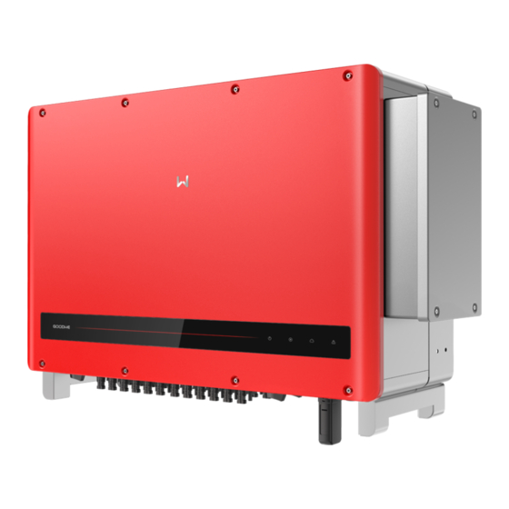
Page 12: Appearance
03 Product Introduction User Manual V1.0-2022-05-04 3.4 Appearance 3.4.1 Parts GW250K-HT , and GW225K-HT GW225KN-HT, and GW250KN-HT... - Page 13 03 Product Introduction User Manual V1.0-2022-05-04 Parts Description Control PV input terminal 1-3, to connect or DC Switch 1-3 disconnect the PV string. PV Input Terminal 1-3 Used to connect the PV strings. (Controlled by DC Switch 1-3) PV Input Terminal 7-9 Used to connect the PV strings.
-
Page 14: Dimensions
03 Product Introduction User Manual V1.0-2022-05-04 Parts Description External Fan Used to cool the inverter. Indicator Indicates working state of the inverter. Optional. Used to check the parameters of the LCD (optional) inverter. Optional. Used to control contents displayed on the Button (optional) screen. -
Page 15: Indicators
03 Product Introduction User Manual V1.0-2022-05-04 3.4.3 Indicators Model without LCD Model with LCD Indicator Status Description ON = EQUIPMENT POWER ON OFF = EQUIPMENT POWER OFF ON = THE INVERTER IS FEEDING POWER OFF = THE INVERTER IS NOT FEEDING POWER SINGLE SLOW FLASH = SELF CHECK BEFORE CONNECTING TO THE GRID SINGLE FLASH = CONNECTING TO THE GRID... -
Page 16: Nameplate
03 Product Introduction User Manual V1.0-2022-05-04 3.4.4 Nameplate The nameplate is for reference only. Goodwe trademark, product type, and product model Technical parameters Safety symbols and certification marks Contact information and serial number... -
Page 17: Check And Storage
04 Check and Storage User Manual V1.0-2022-05-04 4 Check and Storage 4.1 Check Before Receiving Check the following items before receiving the product. 1. Check the outer packing box for damage, such as holes, cracks, deformation, and others signs of equipment damage. Do not unpack the package and contact the supplier as soon as possible if any damage is found. -
Page 18: Storage
04 Check and Storage User Manual V1.0-2022-05-04 NOTICE • The number of PV connectors and the PV terminals in the inverter is the same. • The type and number of the communication connector are decided by the selected communication method. •... -
Page 19: Installation
User Manual V1.0-2022-05-04 05 Installation 5 Installation 5.1 Installation Requirements Installation Environment Requirements 1. Do not install the equipment in a place near flammable, explosive, or corrosive materials. 2. Install the equipment on a surface that is solid enough to bear the inverter weight. 3. - Page 20 05 Installation User Manual V1.0-2022-05-04 Installation Angle Requirements • Install the inverter vertically or at a minimum back tilt of 10 degrees. • Do not install the inverter upside down, forward tilt, back forward tilt, or horizontally. Installation Tool Requirements The following tools are recommended when installing the equipment.
-
Page 21: Inverter Installation
User Manual V1.0-2022-05-04 05 Installation 5.2 Inverter Installation 5.2.1 Moving the Inverter CAUTION Move the inverter to the site before installation. Follow the instructions below to avoid personal injury or equipment damage. 1. Consider the weight of the equipment before moving it. Assign enough personnel to move the equipment to avoid personal injury. - Page 22 05 Installation User Manual V1.0-2022-05-04 Mounting on the plate NOTICE • Contact the dealer or the after sales center to purchase the handle if it is needed. • The hoist ring should be prepared by customers. Lifting the Inverter The DC switch locking hole is for Australia only.
- Page 23 User Manual V1.0-2022-05-04 05 Installation Hoisting the Inverter 2~3N·m The DC switch locking hole is for Australia only.
-
Page 24: Electrical Connection
User Manual V1.0-2022-05-04 06 Electrical Connection 6 Electrical Connection 6.1 Safety Precautions DANGER • Disconnect the DC switch and the AC output switch of the inverter to power off the equipment before any electrical connections. Do not work with power on. Otherwise, an electric shock may occur. - Page 25 User Manual V1.0-2022-05-04 06 Electrical Connection Cable Type Cable Specification Cross sectional area S ≥ S/2. S is the cross PE cable Outdoors Cable sectional area of the output phase wire. PV standard cable that • Conductor cross-sectional area: 4~6mm DC cable meets 1500V standard.
-
Page 26: Connecting The Pe Cable
User Manual V1.0-2022-05-04 06 Electrical Connection 6.2 Connecting the PE Cable WARNING • The PE cable connected to the enclosure of the inverter cannot replace the PE cable connected to the AC output port. Both of the two PE cables must be securely connected. •... -
Page 27: Connecting The Pv Input Cable
User Manual V1.0-2022-05-04 06 Electrical Connection 6.3 Connecting the PV Input Cable DANGER Confirm the following information before connecting the PV string to the inverter. Otherwise, the inverter may be damaged permanently or even cause fire and cause personal and property losses. - Page 28 User Manual V1.0-2022-05-04 06 Electrical Connection Devalan DC Connector 7~8mm 7~8mm Click ≤1500V Click...
- Page 29 User Manual V1.0-2022-05-04 06 Electrical Connection MC4 DC Connector 7~8mm 7~8mm ≤1500V Click Click...
-
Page 30: Connecting The Ac Output Cable
User Manual V1.0-2022-05-04 06 Electrical Connection 6.4 Connecting the AC Output Cable WARNING Do not connect loads between the inverter and the AC switch directly connected to it. Where an external RCD (Residual Current Device) is required in addition to the built-in RCMU (Residual Current Monitoring Unit), and a type A RCD must be used to avoid tripping. - Page 31 User Manual V1.0-2022-05-04 06 Electrical Connection 34-36mm 22-24mm 22-28mm 11-14mm 52-54mm 44-46mm 32-35mm 62-64mm 58-60mm 67mm L2=L1+3mm L1 L2 L3 25~30N·m 2.5~3N·m 7~9N·m NOTICE • Make sure that the cables are connected correctly and firmly after connections. Clean all the debris in the maintenance compartment.
-
Page 32: Communication
RS485 port on the data 2: RS485 B logger. 3: RS485 A You can refer to SCB3000 User Manual. RS485 COM2 4: RS485 B Visit https://en.goodwe.com/Ftp/EN/ 5: Grounding Downloads/User%20Manual/GW_ 6: Grounding SCB3000_User%20Manual-EN.pdf to get the user manual. Reserved COM3... - Page 33 User Manual V1.0-2022-05-04 06 Electrical Connection NOTICE Connect the RS485 cable using a 6PIN communication terminal as follows. COM2 (RS485) RS485-A RS485-B RS485-A RS485-B Grounding Grounding 6.5mm 25mm 0.3~0.4N·m...
- Page 34 User Manual V1.0-2022-05-04 06 Electrical Connection Remote Shutdown and Emergency Power Off networking scenario Remote Shutdown: For Europe only. Emergency Power Off: For India only. Inverter N Inverter 2 Inverter 1 Control room 1 ≤ N ≤ 20 Remote Shutdown or Remote Shutdown or Remote Shutdown or Emergency Power Off...
- Page 35 User Manual V1.0-2022-05-04 06 Electrical Connection 6.5mm 25mm Function +24V SHUTOFF1 Reserved Reserved +24V SHUTOFF2 0.3~0.4N·m NOTICE The Remote Shutdown communication port is installed with a short circuit wire. Remove the short circuit wire and keep it properly when enabling the Remote Shutdown function.
-
Page 36: Installing The Communication Module
NOTICE • Refer to the delivered communication module user manual to get more introduction to the module. For more detailed information, visit www.goodwe.com. • Remove the communication module using the unlock tool. The manufacturer shall not be liable for the port damage if the module is removed without the unlock tool. -
Page 37: Equipment Commissioning
User Manual V1.0-2022-05-04 07 Equipment Commissioning 7 Equipment Commissioning 7.1 Check Items Before Switching Power ON Check Item The inverter is firmly installed in a clean place where is well-ventilated and easy to operate. The PE cable, DC input cable, AC output cable, and communication cable are connected correctly and securely. -
Page 38: System Commissioning
08 System Commissioning User Manual V1.0-2022-05-04 8 System Commissioning 8.1 Indicators and Button Model without LCD Model with LCD Indicator Status Description ON = EQUIPMENT POWER ON OFF = EQUIPMENT POWER OFF ON = THE INVERTER IS FEEDING POWER OFF = THE INVERTER IS NOT FEEDING POWER SINGLE SLOW FLASH = SELF CHECK BEFORE CONNECTING TO THE GRID SINGLE FLASH = CONNECTING TO THE GRID... -
Page 39: Setting Inverter Parameters Via Lcd
08 System Commissioning User Manual V1.0-2022-05-04 LCD Button Description Stop pressing the button for a period in any page, the LCD will get dark and go back to the initial page, which means the parameter in that page has been saved successfully. 8.2 Setting Inverter Parameters via LCD NOTICE •... -
Page 40: Lcd Menu Introduction
08 System Commissioning User Manual V1.0-2022-05-04 8.2.1 LCD Menu Introduction This part describes the menu structure, allowing you view inverter information and set parameters more conveniently. First level menu Second level menu Menu Submenu Long press for 2 s Grid-tied power generation 50 Hz grid voltage Power = XXXXX watts Long... -
Page 41: Inverter Parameter Introduction
08 System Commissioning User Manual V1.0-2022-05-04 8.2.2 Inverter Parameter Introduction Parameters Description Home page. Indicates the real-time power of the inverter. Long press Normal for 2s to check the current safety code. E-Today Check the generated power of the system for that day. E-Total Check the total generated power of the system. - Page 42 08 System Commissioning User Manual V1.0-2022-05-04 Parameters Description With LVRT on, the inverter will stay connected with the utility grid LVRT when a short-term utility grid low voltage exception occurs. With HVRT on, the inverter will stay connected with the utility grid HVRT when a short-term utility grid high voltage exception occurs.
-
Page 43: Setting Inverter Parameters Via App
2. Set grid parameters and communication parameters of the inverter. 3. Maintain the equipment. For more details, refer to the SolarGo APP User Manual. Scan the QR code or visit https:// en.goodwe.com/Ftp/EN/Downloads/User%20Manual/GW_SolarGo_User%20Manual-EN.pdf get the user manual. SolarGo App SolarGo App User Manual 8.4 Monitoring via SEMS Portal... -
Page 44: Removing The Inverter
09 Maintenance User Manual V1.0-2022-05-04 9.2 Removing the Inverter WARNING • Make sure that the inverter is powered off. • Wear proper PPE before any operations. Step 1 Disconnect all the cables, including DC cables, AC cables, communication cables, the communication module, and PE cables. - Page 45 User Manual V1.0-2022-05-04 09 Maintenance Fault Cause Solutions 1. Check whether other electrical devices under the same grid connection point is working normally, and whether the main supply is normal. 2. Make sure that the grid frequency is within the allowed range. The utility grid 3.
- Page 46 09 Maintenance User Manual V1.0-2022-05-04 Fault Cause Solutions DC Bus High AC HCT Fail 1. Make sure that the software version is Inverter internal the latest one. GFCI Fail fault. 2. Restart the inverter to check whether the inverter can work properly. Relay Check Fail EEPROM R/W Fail...
-
Page 47: Routine Maintenance
User Manual V1.0-2022-05-04 09 Maintenance 9.5 Routine Maintenance Maintaining Item Maintaining Method Maintaining Period Check the heat sink, air intake, and air System Clean Once 6-12 months outlet for foreign matter or dust. Check the fan for proper working status, Once a year low noise, and intact appearance. -
Page 48: Technical Parameters
10 Technical Parameters User Manual V1.0-2022-05-04 10 Technical Parameters Technical Data GW250K-HT GW225K-HT GW250KN-HT GW225KN-HT Input Max.Input Power (kW) Max.Input Voltage (V) 1500 1500 1500 1500 MPPT Operating Voltage Range 500~1500 500~1500 500~1500 500~1500 Start-up Voltage (V) Nominal Input Voltage (V) 1160 1160 1160... - Page 49 User Manual V1.0-2022-05-04 10 Technical Parameters Technical Data GW250K-HT GW225K-HT GW250KN-HT GW225KN-HT Power Factor ~1 (Adjustable from 0.8 leading to 0.8 lagging) Max. Total Harmonic Distortion <3% Maximum Output Overcurrent Protection (A) Efficiency Max. Efficiency 99.0% 99.0% 99.0% 99.0% European Efficiency 98.5% 98.5% 98.7%...
- Page 50 10 Technical Parameters User Manual V1.0-2022-05-04 Technical Data GW250K-HT GW225K-HT GW250KN-HT GW225KN-HT Operating Temperature Range -30 ~ 60(60 °C for outdoor unconditioned with solar effects.) (℃) Relative Humidity 0~100% Max. Operating Altitude (m) 5000 (>4000 derating) Cooling Method Smart Fan Cooling Display LED (LCD optional), Bluetooth + APP Communication...
- Page 51 User Manual V1.0-2022-05-04 10 Technical Parameters Overvoltage levels: Overvoltage I: Devices connected to the circuit which can limit instantaneous overvoltage to a relatively low level. Overvoltage II: Energy-consuming devices powered by fixed power distribution equipment, including appliances, portable tools, and other household and similar equipment. Overvoltage III is also applicable if there are special requirements for the reliability and applicability of the equipment.
- Page 52 GoodWe Website GoodWe Technologies Co., Ltd. No. 90 Zijin Rd., New District, Suzhou, 215011, China www.goodwe.com Local Contacts service@goodwe.com...
Need help?
Do you have a question about the HT Series and is the answer not in the manual?
Questions and answers