Goodwe HT Series User Manual
Solar inverter
Hide thumbs
Also See for HT Series:
- User manual (60 pages) ,
- Quick installation manual (2 pages) ,
- User manual (18 pages)
Table of Contents
Advertisement
Quick Links
Advertisement
Table of Contents

Subscribe to Our Youtube Channel
Related Manuals for Goodwe HT Series


Summary of Contents for Goodwe HT Series
- Page 1 User Manual Solar Inverter HT Series V2.0-2021-10-27...
-
Page 2: Table Of Contents
Contents 1 Symbol Definition 2 Safety Instructions 3 Product Introduction 3.1 Product Naming Rules 3.2 Application 3.3 Items supplied 3.4 Appearance 4 Installation 4.1 Installation Instructions 4.2 Select Installation Position 4.3 Install the Inverter 4.4 Electrical Connections 4.5 Communication Connections 5 Operation Instructions 5.1 Description of LCD and Buttons 5.2 Fault Information... -
Page 3: Symbol Definition
1 Symbol Definition Safety warning - Ignore Safety warning may cause minor or moderate injuries. Recyclable High voltage warning Keep this side up Hot surface burning warning Maximum 4 boxes stacked Not to be disposed of as ordinary waste, but to be recycled in special ways Fragile Keep away from moisture... -
Page 4: Safety Instructions
2 Safety Instructions HT series grid-tied PV inverters are designed and tested in compliance with relevant safety regulations by manufacturer. Please strictly follow the safety precautions when installing or maintaining the electrical equipment. Any improper operations may cause serious injuries or property loss to the operators and third parties. -
Page 5: Product Introduction
3. HT - model code 3.2 Application The HT series inverters are three-phase grid-tied PV string inverters that convert the DC power generated by PV strings into AC power and feed the qualified power into the power grid. The inverters are transformerless. The HT inverters can be applied in grid-tied PV systems of large-scale or commercial and industrial PV systems. -
Page 6: Items Supplied
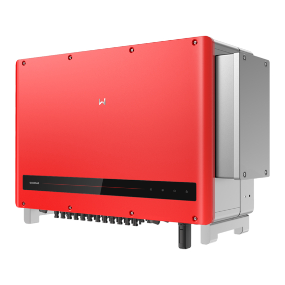
3.3 Items supplied RS485 Inverter Mounting bracket Positive DC connector Negative DC connector Communication connector Bluetooth box Assembling bolt Connection terminal Documents [1] Screwdriver [1] Documents: user manual, business license and certificate. 3.4 Appearance Check the product to confirm it is the right model you purchased after unpacking the package. Product appearance shows as below. - Page 7 GW250KN-HT and GW225KN-HT Front/Side/Bottom View Side View Front View Side View Bottom View 1. DC switch* 9. Hook 2. DC terminal 10. Indicator 3. USB port(Bluetooth) 11. Mounting hole for lifting ring or handle 4. RS485 Communication port 12. Mounting hole for handle 5.
- Page 8 Name Description Used to safely disconnect the DC input when it ' s necessary. The inverter will automatically start working when input or output DC switch meets requirements. Turn the DC switch to " OFF " to cut the DC input or to "...
- Page 9 Indicator Description Model without LCD Model with LCD Green Light Green Light Green Light Red light Code Status Description Steady ON: power on OFF: power off Steady ON: normal grid-tied OFF: not grid-tied Blinking slowly: Self-check before grid-tie Blinking fast: Grid-tie soon Steady ON: Wireless monitoring is normal Single blinking: Wireless module reset Double blinking: Not connected to base station...
-
Page 10: Installation
4 Installation 4.1 Installation Instructions • The inverters work optimally when the ambient temperature is not higher than 45°C. • The installation height should preferably be parallel to the line of sight for easier operation and maintenance. • Keep the inverter installed away from flammable and explosive materials. •... -
Page 11: Install The Inverter
4.3 Install the Inverter 4.3.1 Mount on the wall: • The inverters work optimally when the ambient temperature is not higher than 45°C. • The installation height should preferably be parallel to the line of sight for easier operation and maintenance. - Page 12 4.3.2 Mount on the bracket: Step 2: Fix the mounting bracket on the stand Step 1: Mark position holes with the with the combination bolts in the accessory mounting bracket first and drill holes with a pack. diameter of 13 mm and a depth of 65 mm in the wall.
-
Page 13: Electrical Connections
4.4 Electrical Connections The PV string output cannot be grounded. Make sure that the PV insulation resistance to the ground meets the minimum requirement before connecting the PV string to the inverter. 4.4.1 AC Terminal Connection 1. Measure the voltage and frequency of the grid-tied connection point to make sure that they meet the requirements for the grid-tied inverter. - Page 14 Step 2: Adjust the waterproof silicone ring according to actual needs, and route the AC cables through the ring. Note: To ensure the equipment is sealed, please adjust the aperture of the waterproof silicone ring to Adjust aperture of waterproof match the wire diameter.
- Page 15 Step 5: Tighten the screws and place the fireproofing mud before installing the cover. Connection of A Multi-core Cable 25~30N·m 7~9N·m Tightening torque Cover 2.5-3 N.m Connection of A Single-core Cable 25~30N·m 7~9N·m Tightening Cover torque 2.5 - 3 N.m Please use a torque wrench to tighten the AC Output Cable.
- Page 16 4.4.2 AC Circuit Breaker and Leakage Current Protection Device Please arrange a circuit breaker for the inverter as a protector to ensure that the inverter can safely disconnect from the grid. Inverter model Recommended circuit breaker GW250K-HT GW250KN-HT 250 A GW225K-HT GW225KN-HT Note: the inverters cannot share one circuit breaker.
- Page 17 Step 2: There’ s a DC terminal in the accessory kit. Separate the nut from the terminal and take out the waterproof rubber ring. Positive Negative Waterproof rubber ring Step 3: Route the stripped DC cable through the nut and waterproof rubber ring. Positive Negative Step 4: Connect the conductor of the DC cable to the metal DC terminal and crimp them with a...
- Page 18 Step 5: Insert the crimped DC cable into the DC terminal, then place the waterproof rubber ring into the DC terminal and tighten the nut. Positive Negative Step 6: Connect the completed DC terminals to the inverter as shown below.
- Page 19 4.4.4 External Ground Terminal Connection According to EN50178, a PE connector has been added. Customers have to connect this connector to the PE cable when installing the inverter. Please complete the connection following the steps below. Step 1: Strip the selected cable to an appropriate length. (M8 ground terminals prepared by customers) Step 2: Insert the stripped cable into the terminal, and then crimp it with pliers.
-
Page 20: Communication Connections
4.5 Communication Connections 4.5.1 RS485 communication Apply to RS485 models only. Connect the RS485 port of the inverter to the Data Logger. The total length of the connection cable is less than 1000m. Keep the communication cable away from power cables to prevent the communication from being interrupted. - Page 21 Step 2: Strip the selected Shielded Twisted Pair(STP), then crimp it to the terminal. 6.5 mm 25 mm Completed example Use tools to crimp the terminals Step 3: Route the RS485 STP through the communication terminal and connect it to the corresponding port according to the sequence.
- Page 22 4.5.2 Romote Shutdown For inverters installed in Europe, refer to the following steps to connect the rapid shutdown device. Inverter N Inverter 2 Inverter 1 Control 1≤N≤20 room SHUTOFF1 +24V +24V SHUTOFF1 +24V SHUTOFF1 +24V SHUTOFF1 Romote Shutdown Romote Shutdown Romote Shutdown NOTE: When connecting the rapid shutdown device, ensure that the +24V and the SHUTOFF port are connected.
- Page 23 Ports on the inverter For inverters installed in India, refer to the following steps to connect the rapid shutdown device. Inverter N Inverter 2 Inverter 1 Control 1≤N≤20 room SHUTOFF1 +24V +24V SHUTOFF1 +24V SHUTOFF1 +24V SHUTOFF1 Romote Shutdown Romote Shutdown Romote Shutdown 6.5 mm 25 mm...
- Page 24 3. Refer to the SCB3000 manual for PLC connection methods. 4.5.3 Cloud Monitoring After installation, please scan the QR code on the back of this manual or visit www.sems.com.cn. to download goodwe.cloudview APP. Complete the registration, then you can start the cloud monitoring function.
-
Page 25: Operation Instructions
5 Operation Instructions 5.1 Description of LCD and Buttons Note: For inverters without LCD, please scan the QR code left to download and install the SolarGo App, and complete the corresponding configuration operations in the App. SolarGo App Safety Country Setting: If the LCD displays “GW250K-HT Power = XXXXX watts”... - Page 26 *Short press the button once to enter the input current display menu, which is used to display the PV current in "A". *Short press the button once to enter the utility voltage display menu, which is used to display the mains voltage in "V".
- Page 27 Menu Submenu Long press for 2 s Grid-tied power generation 50 Hz grid voltage Power = XXXXX watts Long Short press press Daily power generation: for 2 s Locked 0.0 kWh Long Short press press W: 16 S: 0 Total power generation: for 2 s C: 0 0.0 kWh...
-
Page 28: Fault Information
5.2 Fault Information When abnormal situation occurs, the following error message may display on the screen: Error Message Error Message Grid outage GFCI Chk Fail Vac Fail AC HCT Fail Fac Fail Gnd I Fail Isolation Fail DC Bus Low GFCI Fail HCT Chk Fail DCI High... -
Page 29: Frequently Asked Questions
6 Frequently Asked Questions Normally, the inverter requires no maintenance. If the inverter cannot work normally, refer to the following instructions: When something is wrong, the red indicator on the operation panel will light up, and relevant information will be listed on the APP. Refer to the table below for more details. Type Error Message Error Message... - Page 30 Type Error Message Error Message Relay Fail DCI High EEPROM Fail 1. Disconnect the DC switch. Inverter Internal 2. Turn on the DC switch. Failures Communication 3. Call the local service center if the fault persists. Failure DC Bus High GFCI Device Check Failure 1.
-
Page 31: Technical Parameters
7 Technical Parameters 7.1 Product Specifications Technical Data GW250K-HT GW250KN- GW225K-HT GW225KN- Input Max. Input Voltage ( V) 1500 1500 1500 1500 MPPT Operating Voltage Range (V) 500~1500 500~1500 500~1500 500~1500 Start-up Voltage (V) Nominal Input Voltage (V) 1160 1160 1160 1160 Max. - Page 32 Technical Data GW250K-HT GW250KN- GW225K-HT GW225KN- AC Overcurrent Protection Integrated AC Short Circuit Protection Integrated AC Overvoltage Protection Integrated DC Arc Fault Circuit Interrupter Optional PID Recovery Optional General Data Operating Temperature Range -30 ~ 60 (℃) Relative Humidity 0~100% Max.
- Page 33 Overvoltage levels: Overvoltage I: Devices connected to the circuit which can limit instantaneous overvoltage to a relatively low level. Overvoltage II: Energy-consuming devices powered by fixed power distribution equipment, including appliances, portable tools, and other household and similar equipment. Overvoltage III is also applicable if there are special requirements for the reliability and applicability of the equipment.
-
Page 34: Main Circuit Diagram
7.2 Main Circuit Diagram The main circuit diagram is shown as below: GW250K-HT , GW225K-HT... - Page 35 GW250KN-HT , GW225KN-HT...
-
Page 36: Product Maintenance
8.1 Clean Fan The external fan of the HT series inverter needs to be cleaned with a vacuum cleaner every year. Remove the fan and give it a thorough clean. 1. Turn off the AC circuit breaker first, and then turn off the DC switch;... -
Page 37: Electrical Connection Check
8.3 Electrical Connection Check 1. Check whether the cables are connected. 2. Check whether the PE cables are reliably grounded. 3. Check whether the waterproof covers for unused ports are sealed correctly. Note: Maintain period: every six months. - Page 38 Offical Website SolarGo APP GoodWe Technologies Co.,Ltd. No. 90 Zijin Rd., New District, Suzhou, 215011, China www.goodwe.com service@goodwe.com...
Need help?
Do you have a question about the HT Series and is the answer not in the manual?
Questions and answers